EN
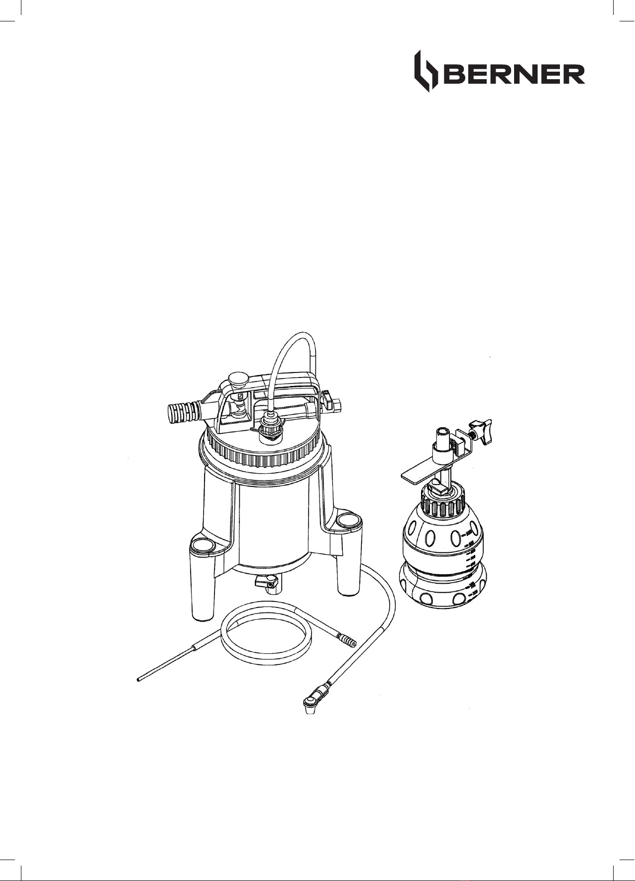
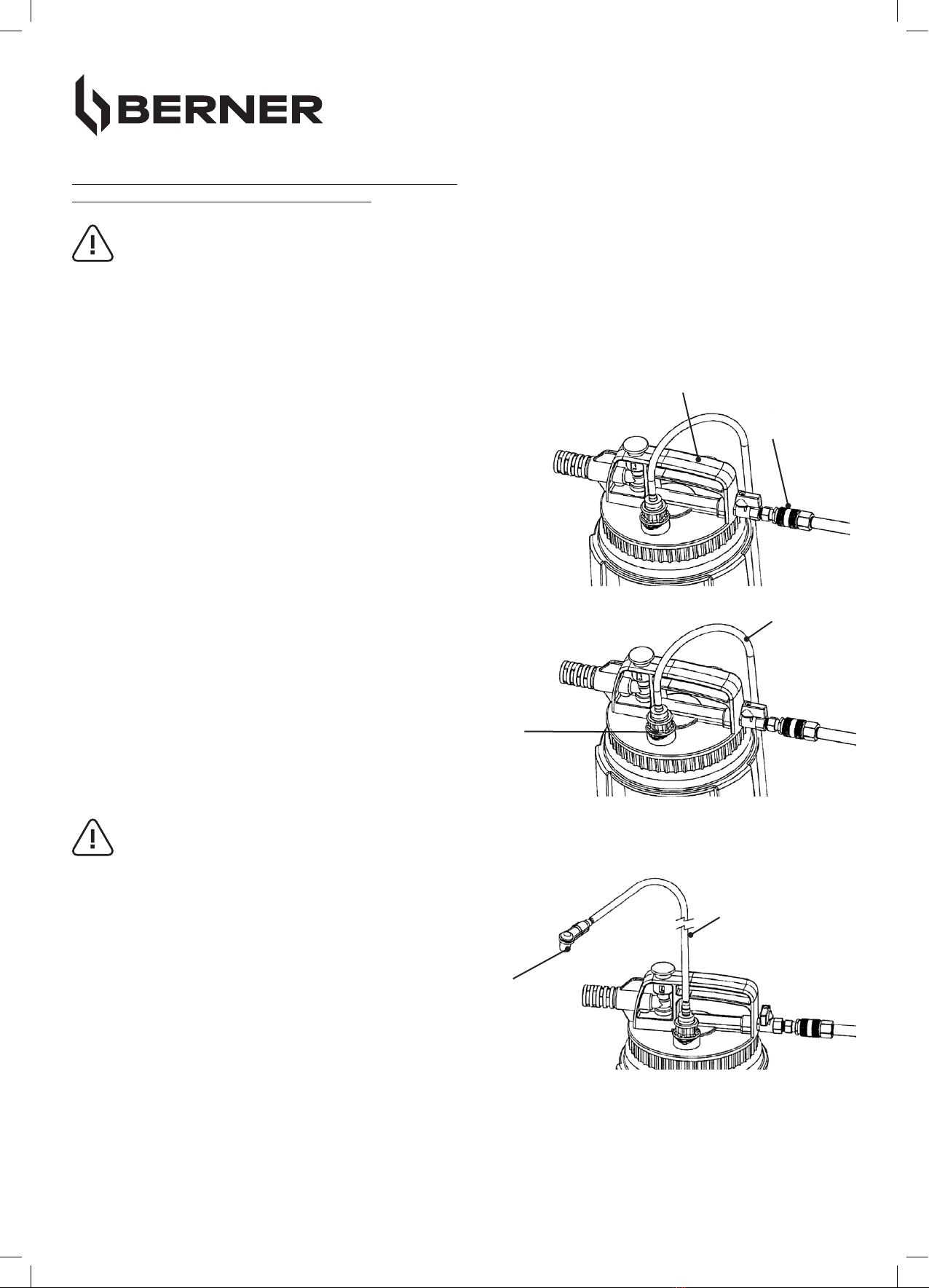
BRAKE BLEEDER PREMIUM 2L SET
Art. 406766
Dear Customer ! Before using this machine it is necessary to study the operation manu-
al carefully. Thank you.
WARRANTY OF THE OPERATOR:
The operator shall ensure that only persons work with the unit who
• have been instructed in the regulations of work safety and accident prevention and are familiar with
the handling of the device.
• have read and understood the operating instructions and the chapter “Safety instructions”.
WARRANTY OF THE USER:
Before starting work, the user shall ensure
• to have been instructed in the regulations of occupational safety and accident prevention and to be
familiar with the handling of the device.
• to have read and understood the operating instructions and the chapter “Safety instructions”.
property can occur in their absence.
MODIFICATIONS OF ANY KIND TO THE PRODUCT ARE PROHIBITED:
personal injury or damage to property.
REPAIRS:
Repairs to the unit may only be carried out by instructed persons. To ensure safety and function, only
original spare parts or special tools may be used.
• Failure to follow the operating instructions and the safety instructions may result in personal injury or damage to
property.
• The safety instructions must not be lost and should be kept in a place accessible to every user.
• Regular maintenance of the unit must be carried out.
• If repairs were carried out and parts had to be replaced, this must be noted.
• Only use original spare parts for repair.
• Wear suitable protective clothing.
• Protect your eyes by wearing eye protection.
• Brake removal equipment does not belong in children’s hands.
GENERAL SAFETY INSTRUCTIONS
BE SURE TO READ THE SAFETY INSTRUCTIONS BEFORE USING THE UNIT FOR THE
FIRST TIME!