Motomaster 299-7001-6 User manual
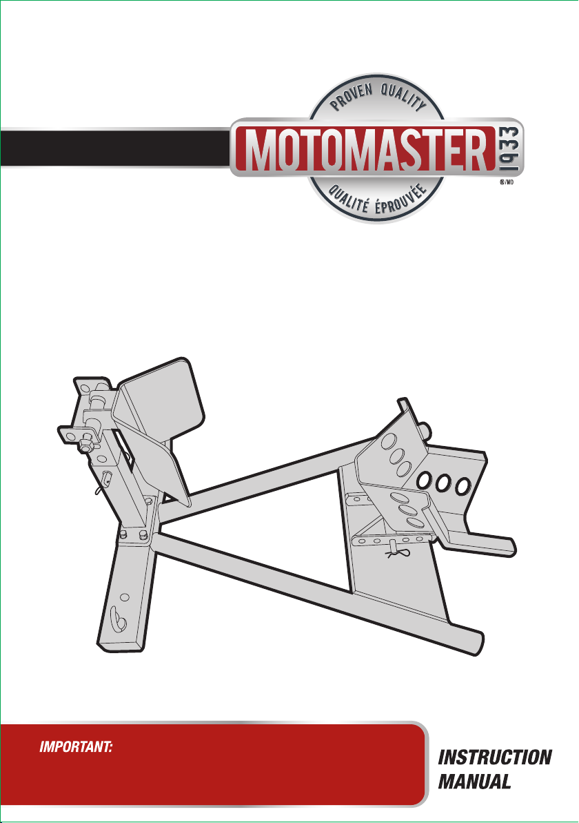
HEAVY-DUTY
MOTORCYCLE WHEEL CHOCK
model no. 299-7001-6
Please read this manual carefully before operating the product
and save it for reference.

1-888-942-6686
299-7001-6
1-888-942-6686.
2
INTRODUCTION

TABLE OF CONTENTS
3
SAVE THESE INSTRUCTIONS
This manual contains important safety and operating instructions. Read all instructions and follow
them while using the products.
TABLE OF CONTENTS
Personal Protective Equipment 5
12
Specications 4
Specic Safety Precautions 6
Parts List
7
Assembly Instructions
Operating Instructions 9
10
Maintenance
Troubleshooting
Warranty
11
13

. 009-0037-6 1-888-942-6686
299-7001-6
INTRODUCTION
SPECIFICATIONS
4
SPECIFICATIONS
Capacity Wheel Diameter
1500 lb (680 kg) 16 – 21" (40.6 – 53.3 cm)
Net Weight
17 lb 10 oz (8 kg)
WORK AREA
• Operate in a safe work environment. Keep your work area clean, well-lit and free
of distractions.
• Keep anyone not wearing the appropriate safety equipment away from the work area.
• Store unused tools properly in a safe and dry location to prevent rust or damage.
Lock tools away and keep out of the reach of children.
199-1501-x
The motorcycle wheel chock securely supports your motorcycle in an upright position with a
locking cradle. The chock adjusts to accommodate a front or rear tire diameter of 16 to 21"
(40.6 to 53.3 cm).
SAFETY 199-1501-x
Keep this manual for safety warnings, precautions, operating or inspection and maintenance
instructions.
WARNING!
Read and understand all instructions before using this tool. The operator must follow basic
precautions to reduce the risk of personal injury and/or damage to the equipment.

• Always wear impact safety goggles that provide front and side protection for
the eyes. Eye protection equipment should comply with CSA Z94.3-07 or ANSI
Z87.1 standards based on the type of work performed.
• Wear gloves that provide protection based on the work materials or to reduce
the effects of tool vibration.
• Wear protective clothing designed for the work environment and tool.
• Non-skid footwear is recommended to maintain footing and balance in the
work environment.
PERSONAL PROTECTIVE EQUIPMENT
5
PERSONAL PROTECTIVE EQUIPMENT
• Do not operate any tool when tired or under the inuence of drugs, alcohol or
medications.
• Avoid wearing clothes or jewellery that can become entangled with the moving
parts of a tool. Keep long hair covered or bound.
Do not overreach when operating a tool. Proper footing and balance enables
better control in unexpected situations.
PERSONAL PRECAUTIONS
Control the tool, personal movement and the work environment to avoid personal injury or
damage to tool.
WARNING!
Wear personal protective equipment approved by the Canadian Standards Association
(CSA) or American National Standards Institute (ANSI).

. 009-0037-6 1-888-942-6686
299-7001-6
• Use the correct tool for the job. This tool was designed for a specic function. Do
not modify or alter this tool or use it for an unintended purpose.
Never attempt to exceed the chock’s weight capacity (see Specications).
Use this chock on stable, solid, level ground capable of withstanding the load. Do
not use on a ramp.
Do not leave the chock before locking the wheel cradle in place with the lock pin.
SPECIFIC SAFETY PRECAUTIONS
6
SPECIFIC SAFETY PRECAUTIONS
WARNING!
Do not operate the tool if any part is missing. Replace the missing part before operating.
Failure to do so could result in a malfunction and personal injury.
WARNING!
DO NOT let comfort or familiarity with product (gained from repeated use) replace strict
adherence to the tool safety rules. If you use this tool unsafely or incorrectly, you can suffer
serious personal injury.
NOTE:
Remove the parts and accessories from the packaging and inspect for damage. Make sure that all
items in the parts list are included.

ASSEMBLY INSTRUCTIONS
7
WARNING!
The wheel chock may be permanently mounted using appropriate mounting hardware.
The wheel chock must be properly mounted to the trailer or truck bed before transport.
ASSEMBLY INSTRUCTIONS
Connect tire stop upper pole (3) and lower pole (4), aligning the holes in the
desired position. Secure in place with the R clip for pole connection (6).
Secure the tire stop lower pole (4) to the base (9) using the four bolts and spring
washers (8).
1
2
fig A
Tire stop upper pole (3)
Tire stop
lower pole (4)
R clip for pole connection (6)
fig B Tire stop
lower pole (4)
Base (9)
Bolts and
spring
washers (8)

. 009-0037-6 1-888-942-6686
299-7001-6
ASSEMBLY INSTRUCTIONS
8
Place the tire stop (1) on upper pole (3), aligning the holes in the desired position.
Secure in place with the bolt set (2).
Place the wheel cradle (12) at the bottom end of the base (9), aligning the holes
in the desired position. Secure in place with the wheel cradle pin (10) and
R clip for wheel cradle (11).
3
4
fig D
Wheel cradle (12)
Base (9)
Wheel cradle
pin (10)
R clip for wheel
cradle (11)
fig C
Tire stop (1)
Upper pole (3)
Bolt set (2)

OPERATING INSTRUCTIONS
9
OPERATING INSTRUCTIONS
• The tire stop has 2 locking
positions and the wheel cradle
has 5 locking positions. To adjust
the positions, extract the R clip
and withdraw the pin. Move to
the desired position, insert the pin
and lock with the R clip.
• To obtain the optimum t for
differing sizes of motorcycle
wheel, adjust the positions and
then test as necessary.
Positioning motorcycle in the chock
• With the wheel cradle in the open position as shown in picture, align the
motorcycle with the chock.
• Push the motorcycle rmly into the chock so that the front tire runs through
the tapered part of the wheel cradle.
• As the weight of the wheel passes over the wheel cradle, it will cause the
wheel cradle to ip over. The front of the tire will be supported by the tire
stop and the rear of the tire by the wheel cradle.
• Check that the motorcycle is stable within the chock before leaving it. If the
wheel is loose, or too high in the chock, extract the motorcycle from the
chock and adjust the positions of the clamps until the optimum t is
achieved.
WARNING!
Wipe external surfaces of the tool with clean cloth.
The wheel cradle will close on the motorcycle tire, securing the bike in an upright position.
For long-term storage, or if the wheel chock is mounted to a mobile platform, secure the
motorcycle with belts and straps (not included).
WARNING!
DO NOT mount the chock on tarmacadam, as the surface may be unstable.
Ensure that the clamps are free from oil and grease before positioning a motorcycle in the chock.
Ensure that the motorcycle is adequately secured to the chock if to be used for transportation purposes.
WARNING!
Ensure that there is nothing attached to the front forks or the fairing of the motorcycle that
will foul on the chock.
Locate the chock in a suitable area. Keep area clean and tidy and free from unrelated
materials and ensure that there is adequate lighting. Also ensure that the oor/ground is level
and strong enough (preferably concrete) to take the weight of the chock and the motorcycle.
Adjusting the tire stop and wheel cradle
Wheel cradle
Wheel cradle
locking position
Tire stop
Tire stop locking position
R clip

. 009-0037-6 1-888-942-6686
299-7001-6
MAINTENANCE
199-1501-x
Maintain the product by adopting a program of conscientious repair and maintenance in
accordance with the following recommended procedures. It is recommended that the general
condition of any tool be examined before it is used. Keep your tool in good repair. The following
chart is based on a normal operation schedule.
199-1501-x
OPERATING INSTRUCTIONSMAINTENANCE
10
Maintenance Interval Maintenance Point
Daily before operating Check for loose screws, misalignment or binding of
moving parts, cracked or broken parts. Wipe the
wheel chock down with a soft cloth and mild
detergent.
After the rst 20 operating hours Check for loose screws, misalignment or binding of
moving parts, cracked or broken parts.
Check if any distortion.
After the rst 50 operating hours or every week Check for loose screws, misalignment or binding of
moving parts, cracked or broken parts.
Check if any distortion.
Removing motorcycle from the chock
• More effort will be required to remove the motorcycle from the chock.
Ensure that the space into which the motorcycle will move is free from
obstructions and people.
• Take a rm stance and hold the motorcycle handlebar grips.
• Pull back the motorcycle with sufcient force to overcome the hold of the
wheel cradle and release the motorcycle from the chock.

TROUBLESHOOTING
Use the table below to troubleshoot problems before contacting service personnel or your local
dealer. If the problem continues after troubleshooting, call your local dealer for assistance.
TROUBLESHOOTING
11
Failure Possible Cause Corrective Action
Screw loose Tighten the screw with correct
screwdriver
Wheel too big Change the wheel cradle position to
another hole

. 009-0037-6 1-888-942-6686
299-7001-6
PARTS LIST
12
No. Description Qty.
1 Tire stop 1
2 M10x110 bolt set 1
3 Tire stop upper pole 1
4 Tire stop lower pole 1
5 Pole connect pin 11.5x68 1
6 R clip for pole connection 1
7 Base eyebolt 2
8 M8x15 bolt & spring washer 4
9 Base 1
10 Wheel cradle pin 11.5x123 1
11 R clip for wheel cradle 1
12 Wheel cradle 1
No. Description Qty.
12
11
10
9
8
7
4
5
6
3
2
1

WARRANTY
This Motomaster product carries a one (1) year warranty against defects in workmanship
and materials. At its discretion, Motomaster Canada agrees to have any defective part(s)
repaired or replaced free of charge, within the stated warranty period, when returned by
the original purchaser with proof of purchase. This product is not guaranteed against wear
or breakage due to misuse and/or abuse.
Made in China
Imported by Motomaster Canada, Toronto, Canada M4S 2B8.
WARRANTY
13

N° de modèle : 299-7001-6
IMPORTANT : GUIDE
D’UTILISATION
CALE DE ROUE DE
MOTOCYCLETTE
ROBUSTE
Veuillez lire attentivement ce guide avant d'utiliser l'article
et le conserver aux ns de consultation ultérieure.

N° de modèle : 299-7001-6 / Communiquez avec nous au 1 888 942-6686
2
INTRODUCTION
S'IL Y A DES PIÈCES MANQUANTES OU ENDOMMAGÉES, OU SI VOUS
AVEZ LA MOINDRE QUESTION, VEUILLEZ COMMUNIQUER AVEC LE
SERVICE D'ASSISTANCE TÉLÉPHONIQUE SANS FRAIS AU
1 888 942-6686.
guide
guide
guide

3
TABLE DES MATIÈRES
Équipement de protection individuelle 5
12
Fiche technique 4
Consignes de sécurité spéciques 6
Liste des pièces
7
Instructions d'assemblage
Consignes d'utilisation 9
10
Entretien
Dépannage
Garantie
11
13
CONSERVEZ CES CONSIGNES
Le présent guide contient d'importantes consignes de sécurité et de fonctionnement. Veuillez lire toutes
les consignes et les respecter pendant que vous utilisez cet article.
TABLE DES MATIÈRES

. 009-0037-6
N° de modèle : 299-7001-6 / Communiquez avec nous au 1 888 942-6686
INTRODUCTION
FICHE TECHNIQUE
4
FICHE TECHNIQUE
Capacité Diamètre de la roue
1500 lb (680 kg) 16 à 21 po (40,6 à 53,3 cm)
Poids Net
17 lb 10 oz (8 kg)
AIRE DE TRAVAIL
Travaillez dans un environnement de travail sécuritaire. Gardez votre aire de travail
propre, bien éclairée et exempte de toute distraction.
Assurez-vous que les personnes qui ne portent pas l'équipement de sécurité
approprié ne se trouvent pas à proximité de l'aire de travail.
Rangez les outils correctement dans un lieu sécurisé et sec. Gardez les outils hors
de la portée des enfants.
199-1501-x
La cale de roue pour motocyclette retient solidement votre motocyclette en position verticale dans
un berceau de verrouillage. La cale de roue s’ajuste en fonction d’un pneu avant ou arrière d’un
diamètre de 16 à 21 po (40,6 à 53,3 cm).
SÉCURITÉ199-1501-x
Conservez ce manuel qui contient les avertissements de sécurité, les précautions, les instructions
de fonctionnement ou d'inspection et d'entretien.
AVERTISSEMENT !
Veuillez lire et comprendre toutes les instructions avant d'utiliser cet outil. L'utilisateur doit
respecter les précautions de base lorsqu'il utilise cet outil an de réduire le risque de blessure
ou de dommage à l'équipement.

• Portez toujours des lunettes antiprojections qui offrent une protection frontale et
latérale pour les yeux. L'équipement de protection des yeux devrait être conforme
à la norme CSA Z94.3-07 ou ANSI Z87.1 en fonction du type de travail effectué.
Portez des gants qui protègent en fonction des matériaux de travail et pour réduire
les effets des vibrations de l'outil.
Portez des vêtements de protection conçus pour l'environnement de travail et pour
l'outil.
Les chaussures antidérapantes sont recommandées pour maintenir la stabilité et
l'équilibre au sein de l'environnement de travail.
ÉQUIPEMENT DE PROTECTION INDIVIDUELLE
5
ÉQUIPEMENT DE PROTECTION INDIVIDUELLE
N'utilisez pas l'outil si vous êtes fatigué ou sous l'effet de drogues, d'alcool ou de
médicaments.
Évitez de porter des vêtements ou des bijoux pouvant se prendre dans les pièces
mobiles d'un outil. Gardez les cheveux longs recouverts ou attachés.
N'utilisez pas l'outil si vous devez étirer les bras pour vous en servir. Une stabilité
et un équilibre appropriés sont nécessaires an d'avoir un meilleur contrôle en cas
de situations inattendues.
PRÉCAUTIONS À PRENDRE
Gardez le contrôle de l'outil, de vos mouvements et de l'environnement de travail pour éviter les
blessures ou le bris de l'outil.
AVERTISSEMENT !
Portez de l'équipement de protection personnelle homologué par l'Association canadienne de
normalisation (CSA) ou l'American National Standards Institute (ANSI).

. 009-0037-6
N° de modèle : 299-7001-6 / Communiquez avec nous au 1 888 942-6686
• Utilisez le bon outil pour la tâche à effectuer. Cet outil a été conçu pour une
utilisation spécique. Évitez de modier ou d'altérer cet outil ou de l'utiliser à une
n autre que celle pour laquelle il a été conçu.
Ne tentez jamais de dépasser la capacité pondérale de la cale de roue
(voir Spécications).
Utilisez cette cale de roue sur une surface stable, solide et de niveau qui est
capable de soutenir la charge. Ne l’utilisez pas sur une rampe.
Ne laissez pas la cale de roue avant d’avoir bloqué le berceau de roue au moyen
du levier de sécurité.
CONSIGNES DE SÉCURITÉ SPÉCIFIQUES
6
CONSIGNES DE SÉCURITÉ SPÉCIFIQUES
REMARQUE :
Retirez les pièces et les accessoires de l'emballage et vériez s'il y a des dommages.
Assurez-vous que tous les articles sur la liste de pièces sont compris.
AVERTISSEMENT !
Portez de l'équipement de protection personnelle homologué par l'Association canadienne de
normalisation (CSA) ou l'American National Standards Institute (ANSI).
AVERTISSEMENT !
Ne permettez PAS au confort ou à votre familiarisation avec l'outil (obtenus après un emploi
répété) de se substituer à une adhésion stricte aux règles de sécurité de l'outil. Si vous utilisez
cet outil de façon dangereuse ou incorrecte, vous pouvez subir des blessures corporelles graves.

INSTRUCTIONS D’ASSEMBLAGE
7
AVERTISSEMENT !
La cale de roue peut être montée en permanence au moyen des éléments de montage appropriés.
La cale de roue doit être xée correctement à la remorque ou la plate-forme avant le transport.
INSTRUCTIONS D’ASSEMBLAGE
1
2
fig A
Poteau supérieur (3) de
la butée de roue
Poteau inférieur
(4) de la butée de roue
Goupille bêta (6) pour la
xation des poteaux
Poteau inférieur
(4) de la butée
de roue
Base (9)
Boulons et de
rondelles à
ressort (8)
fig B
Assemblez le poteau supérieur (3) au poteau inférieur (4) de la butée de roue
en alignant les trous à la position souhaitée. Fixez l'assemblage au moyen de
la goupille bêta (6).
Fixez le poteau inférieur (4) de la butée de roue à la base (9) au moyen de
quatre boulons et rondelles à ressort (8).
Table of contents
Languages:
Other Motomaster Service Equipment manuals