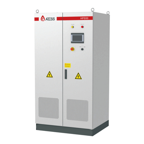
ATESS HPS5000TLS User manual


7 8
Figure 3-2-1 ATESS HPS-TLS circuit diagram
3 Product description
ATESS HPS5000TLS/HPS7500TLS/HPS10000TLS hybrid inverter is designed for
energy storage system, it converts DC current generated by battery bank into AC
current and feed into the load/grid, also it can take power from solar inverter or grid
to charge battery .
3.1 Energy Storage system
3.2 Circuit diagram of the inverter
ATESS HPS5000TLS/HPS7500TLS/HPS10000TLS hybrid inverter is designed for
energy storage system, it converts DC current generated by battery bank into AC
current and feed t into the load/grid, also it can take power from solar inverter or grid
to charge battery .

109
3.4 The layout of the main parts
3.4.1 External layout
Figure 3-4-1-1 Inverter appearance
No. Name Description
1
2
3
4
Display
PD compartment
Cable inlet and outlet
Heat dissipation screen
Inverter setting, browsing and operation
status display
For power input and output installation
and maintenance
For input and output power cable
conneciton
For hot and cool air ventilation
Figure 3-3-1 Part description
Figure 3-4-1-2 LED indicators
LED
RUN
STOP
FAULT
Description
Lit when inverter is in normal operation
Lit when inverter is stopped
Lit when inverter is in fault condition
Port
SWITCH I
INPUT I
BAT/LOAD/GRID
Description
PV DC switch
PV cable gland
Cable gland for input and output
Cable inlet and outlet
Figure 3-4-1-3 Inverter cable inlet and outlet
Indicator
There are 3 LED indicators on the inverter which is used to display the current
status of the inverter.

11
12
Communication port
3.4.2 Inner component layout
Inner component layout is shown in below figure:
DC/AC breaker
The AC main switch can be used to disconnect the AC side of the inverter from the
grid. The DC main switch can be used to make the DC side of the inverter
disconnected from the battery assembly. If you use AC main breaker under load , the
components of the inverter will be subjected to considerable stress. Frequent use of
the AC main switch can result in individual components damage due to stress and
may cause inverter failure.
Fuse
There is a mark on the fuse holder, the mark turns red indicates that the fuse is
damaged; professional technicians are required to check the cause of the damage of
the fuse and then replace the fuse.
3.5 working mode
HPS5000TLS/HPS7500TLS/HPS10000TLS is designed with flexible working modes:
3.5.1. Off-grid mode
(1)When PV power is higher than load power, PV supply priority to load power,then
to the battery charge.
(2) Battery discharge automatically when PV power is lower than load power.
3.5.2 Grid-connected load priority mode
(1) Make full use of PV power. When the PV power is insufficient, the battery is given
priority for the load, and the second grid is used for the load.
(2) This mode has two situations: anti-backflow and no backflow prevention. PV
power meets charging power and load to prevent power feeding to grid.
(3) Working status:
A. When the PV power is greater than the load power, the PV preferentially supplies
power to the load, and the residual power is charged to the battery;
B. When the PV power does not meet the load, the battery is automatically
discharged. If the battery is discharged to the undervoltage protection point, the PV
and the grid together supply power to the load. To protect the battery, the PV side will
use a small amount of power to charge the battery, and the battery can be recharged
to a certain extent to restore power.
3.5.3 On-grid backup priority mode
(1) Grid supplies power to load and charges battery when PV power insufficient.
(2)When the back-flow-prevention works, PV power can meet battery charge and
load power.
(3) operation state
A.PV supply priority to the load, the remaining to load and grid when PV power is
higher than load power
B. When PV power is lower than the charging power, PV supply priority to battery,
the grid supplies to load and battery.
C20%If battery is not discharged at this mode or inverter switched to other mode,
float charge after one week, then discharge battery
GND
IN
GND
EPO
CANB
PE L H
CANA
PE L H
MMS
PE L H
PWM
PE L H
RS485
PE B A
CANB
PE L H
CANA
PE L H
MMS
PE L H
PWM
PE L H
RS485
PE B A
1 2 3
1 2 3
1 2 3
1 2 3
RS232
LCD-USB
CANB CANA PWMMMS RS485
PE L H PE L H PE L H PE L H PE B A
GND
IN
GND
EPO
AC breaker
DC breaker
Fuse

13 14
3.5.4 On-grid economic priority mode
(1)At this mode, the inverter can prevent the current from flowing back by default, PV
will only need to meet battery charge and load power.
(2)Valley price: working logic is the same to the backup priority mode’s. PV and grid
supply priority to battery, the remaining to load.
(3)Fair price:
A. Battery can neither discharge nor be charged by grid.
B.PV power supply priority to load, the remaining to battery when PV power is higher
than load power.
C. When PV power is lower than load power, PV and grid supply to load, PV does not
charge battery
(4)Peak price:
A. Grid will not charge battery.
B. When PV power is higher than load power, PV supply to load , the remaining to
battery.
C. When PV power is lower than load power, there are two conditions:
a. When battery voltage is normal, PV and battery supply to load.
b. When the battery is under voltage, battery will not discharge, PV and grid supply to
load only, not to battery.
3.5.5 On/Off-gird switch
Operation logic: When grid power on, HPS can switch into on-grid mode
automatically; when grid power off, HPS can switch into off-grid mode automatically.
3.5.6 Fault mode
When the Hybrid energy system fails, the inverter will immediately disconnect the
AC/DC contactor and enters into the fault mode, so as to ensure the safety of the
system. Inverter continuously monitors fault status and will not enter charge and
discharge mode until the fault is eliminated.
3.5.7 Permanent fault mode
When the Hybrid energy system is in serious failure, the inverter will immediately
disconnect the AC/DC contactor and enters into the Permanent fault mode, so as to
ensure the safety of the system. For example: inverter module failure etc. please
contact your local dealer or ATESS directly when inverter enters permanent fault
mode, repairmen on site is not allowed without authorization of ATESS.
3.6 Battery setting
Battery is an important part of energy storage system, strict protection is needed in
the whole operation process. Protection threshold need to be set on HPS10 to
ensure safe operation of battery, parameters including: battery quantity and unit
quantity, capacity, charge current, discharge current, over voltage protection, under-
voltage protection and so on. Battery parameter setting need to be done by
professional personnel. Improper setting of battery will affect the normal
3.7 Storage
If there is a long time before installation or operation, the ATESS
HPS5000TLS/HPS7500TLS/HPS10000TLS should be stored appropriately.
> The packaging should be restored to its original state;
> Retain the desiccant in the packaging.
> The ATESS HPS5000TLS/HPS7500TLS/HPS10000TLS can only be stored when it
is stopped and all the doors are closed in a dry room to protect the internal circuits
against dust and moisture.
> Storage temperature range: -40~55 ℃
> Storage relative humidity range: 5 %~95 %
> Operating temperature range: -25~55 ℃
> Operating relative humidity range:5 %~95%
> Max. altitude:2000 m
16
CAUTION
· Strictly prohibited storage without packing!
· Avoid storage in direct sunlight!
· Keep upright and no stacking on top of the crate.

15 16
3.8 Packaging information
No. Name Unit
1
2
3
4
5
Inverter main unit
Wall-mounting accessory
Expansion bolt
user manual
certificate
pcs
set
set
pcs
pcs
Quantity
1
1
6
1
1
Table 3-8-1 Packaging information
Products installation 4
4.1 Installation condition requirements
To ensure normal operation of the machine, the installation environment is required
as follows:
A. The wall for mounting HPS should be solid and able to bear the weight of HPS in
the long term.
B. Installation space should be sufficient to cover HPS dimension, HPS dimension
and installation gap please see below photo:
C. Do not install HPS on flammable or heat vulnerable materials or buildings
D. Do not install HPS in a space without good ventilation or dusty, it will cause low
cooling fan efficiency, then reduce HPS efficiency, the fan and fan cover should be
checked and cleaned every 6 months
E. To avoid overheat and power derating, please do not expose HPS under the sun
F. Environment temperature around HPS should be -25~55
G. HPS can be installed on vertical or tilted surface as shown in below figure:
H. Please ensure sufficient space
I. Do not install HPS beside TV antenna, mobile network devices or lightning rods to
ground.
J. Do Not install HPS in residential area
K. Do not install HPS in area within reach of children

17 18
4.2 Installation environment
Although HPS is with IP54 protection level, it is not recommended to install it under
direct sun or direct rain/snow to ensure long term performance, below installation
environment for reference:
To avoid inverter life span decrease, it is recommended to install shading shield on
top of inverter, distance between inverter and top shield please refer to below figure
3.8:
Warning:
When environment temperature is too high, inverter derating is
normal operation, but if derating occurs frequently, please check
inverter heat dissipation surface or consider to move inverter to area
with better ventilation. If fan is dirty please clean, if inverter inner
fault please seek for professional service.
4.3 Space requirement
When installing HPS, reasonable distance should be kept for maintenance and
ventilation, please refer to below figure:

19 20
4.4 Tools and spare parts required for whole machine installation
Tools and spare parts required for installation is as follows:
• Hoisting crane, forklift or fork lift truck (with the capacity for bearing the weight of
the inverter)
• Torque wrench
• Screwdriver
• Wire stripper
• Terminal crimping machine
• Heat dryer
• Megger and multimeter
4.5 Mechanical installation
4.5.1 Installation of wall-mounting kit
Before installing the wall-mounting kit, please check and make sure there’s
no electric cable and gas pipe in the location of installation.
Figure 4-5-1-1 installation gap
Steps:
A: Drill hole according to location of the wall-mounting bracket screw hole, total 6
B. Refer to figure 4 for installation of wall-mounting bracket
Figure 4-5-1-2 bracket installation
Note: wall-mounting bracket must be installed first before installing HPS
4.5.2 Installing HPS
A. keep the inverter balance when hanging it to the bracket
Figure 4-5-2-1 Hanging of inverter

22
21
4.6lectrical installation
4.6.1 Input and output requirements
NOTICE
Caution, risk of danger
• There is a danger of electrical shock of high voltage in inverter ’s
operation; only electricians of professional skills can operate.
•All connections with this equipment shall be done under non-voltage
state.
• The inverter may be damaged if input or output terminal is ncorrectly
plugged.
Failure of acting upon this information may cause serious
1) Battery
Battery string voltage should not exceed 720V, or else inverter will be in faulty mode
2) Three-phase grid
I nv e r t er w il l c on t i n uo u s l y i n sp e c t w h e th e r t h e g r i d s a t is f y t h e g r i d
connectedconditions. The following is the grid limit for satisfaction of local Grid
connected onditions (requirements in different countries may vary, the value can be
setup nd please refer to local grid connected regulations for details), and the grid is
hree-phase grid. Meanwhile, it shall be permitted by local power supply epartment
before install Grid-connected inverted power.
Model HPS5000TLS/HPS7500TLS/HPS10000TLS
Grid Voltage Limit
Grid Frequency Limit
210V~250V
47HZ-51.5HZ/57HZ-61.5HZ
CAUTION!
Caution, risk of danger
The positive and negative of the battery shall not be connected in
reverse. A multimeter shall be used to determine the polarity first, and
then connect into the corresponding input ends of the inverter.Specific
procedures are as follows:
Cable (Cu) Cable Diameter Requirements (mm²)
Model
PV +-
BAT +-
Grid input A B C
Grid input A B C
Communication Wire
Earth Wire
HPS5000TLS/HPS7500TLS/HPS10000TLS
input cable with each at least 4 mm2
cable with each at least 6 mm2
input cable with each at least 4 mm2
0.75mm², shielded Twisted pair is recommended
More than 6 mm².Green and yellow is recommended
Aperture
Φ5,5N*m
Φ5,5N*m
Φ5,5N*m
/
Φ5,5N*m
4.6.2 preparation before cable connection
Before wiring, you need to open the front door of the energy storage controller. The
specific steps are as follows:
Step 1: Turn off the AC and DC air. As shown in the figure below, the PV switch is in
the "OFF" state.
4.6.3 DC side wiring

23 24
Step 1: Cut off the distribution circuit breaker at the DC side, and ensure that no
voltage on the wire at DC side.
Step 2: Confirm the battery positive and negative voltage within range with a
multimeter.
Step 3: Confirm the negative and positive pole with a multimeter
Step 4 Peel the insulation layer of cable
Step5: fix cable lug
1. Place the stripped copper core into the crimping holes of the cable lug
2. Press the cable lug with the terminal crimping machine. The number of crimps
should be more than two
Step 6: fix heat shrinking tube
1. choose heat shrink tube according to cable size, and cut aboug 5cm
2. fix the tube to cable, cover the lug hole
3. use air heater to blow the tube and make it shrink
Step 7: Connect the “Bat+” end of the energy storage controller to the positive
terminal of the battery pack with a cable.
1. Pass the cable through the PG waterproof connector.
2. Secure the copper noses at the ends of the wiring to the “Bat+” end of the energy
storage controller and the positive terminal of the battery pack.
3. Fasten the bolt with a screwdriver or wrench
Step 8: Connect the "Bat -" end of the energy storage controller to the negative
terminal of the battery pack by cable according to the method of step 7.
Step 9: Connect the "PV+" end of the energy storage controller to the positive pole of
the battery board by cable according to the method of step 7.
Step 10: Connect the "PV-" end of the energy storage controller to the negative pole
of the battery board by cable according to the method of step 7.
Step 11: Make sure the wiring is secure; tighten the PG waterproof connector
CAUTION!
Caution, risk of danger
When connecting the AC grid, cut off the circuit breaker at the AC side
to ensure that the AC wire connecting to terminals has no electricity.
4.6.4 AC side wiring
Connect AC grid:
1) Cut off the circuit breaker at AC side, to ensure that the AC wire connecting to
terminals has no electricity. Confirm it with a multimeter.
2)confirm the phase sequence of grid
3)peel the insulation layer of cable
4)fix cable lug
5) fix heat shrink tube
1. choose heat shrink tube according to cable size, and cut aboug 5cm
2. fix the tube to cable, cover the lug hole
3. use air heater to blow the tube and make it shrink
6)
1.Connect the L marked at "Grid" of HPS with "L" of the grid .
2.Connect the N marked at "Grid" of HPS with "N" of the grid.
7) same with step 6, connect load cable L and N to the "L" and "N" port of HPS Load.
Figure 4-6-1-1 AC output cable connection
Bat
+-LOA D
LN
Gri d
LN

26
25
4.6.5 Earthing
Inverter must be earthing well for safety; Please make sure of the connection
between PE in power distribution cabinet and PE copper in the inverter good; and
make sure the earthing cable more than 6mm2 and the earthing resistance must
below 4 ohm.
Inveter earthing busbar please refer to above photo cable inlet and outlet are on the
bottom of inverter, after finishing connection, tighten the cable tighten gland.
Note: the PE busbar is for grounding inside inverter, please do not
change to avoid electric shock risk
4-6-1-2 cable inlet and outlet
4.7 Communication
The HPS series hybrid energy storage system has multiple communication modes.
When users need to monitor the operation status of the energy storage and
discharge system, RS485 serial port or CAN communication mode can be used for
power supply.
4.7.1 RS485
Users can d i rectly u s e t h e RS485/RS232 converter for h o s t c o m p u t e r
communication. The HPS communicates with the HPS through RS485, and finally
communicates with the PC through the RS485 to RS232 datalogger, runs the
monitoring software in the PC, and monitors the running status of the single/multiple
energy storage controllers in real time.
Rs485 communication line uses terminal blocks at both ends, and RS485
communication lines are made by parallel connection of terminals at both ends. The
length should not exceed 1000 meters. As shown in Figure 4-7-1-1
Figure 4-7-1-1
4.7.2 CAN communication
Rate of CAN communication is between 100K and 500K, and the shielded twisted
pair is used for communication to ensure communication quality.
4.8 Installation inspection
Before the inverter is put into operation, it shall be inspected for installation. Two
working men or more shall inspect to ensure correct installation of all installation
according to the following table.
Mechanical inspection
Inverter's bottom is fixed, and the support is stable and reliable.
Enough space is left around inverter.
The ambient temperature, humidity and ventilation satisfy requirements.
Smooth flow of cooling air.
Complete and reliable sealing protection of cabinet.
No deformation and damage to inverter.

27 28
Electrical Installation Inspection
Complete and firm grounding of inverter.
Grid voltage matching the rated input voltage of inverter.
Correct phase sequence of grid connection, and tightening torque meeting requirements.
Correct connection of DC input anode and cathode, and tightening torque meeting requirements.
Correct connection of communication lines, and maintaining a certain distance to other cables.
Mechanical Installation Items Inspection
Other Inspections
All useless conductive parts tied with insulating ribbon.
No tools, spare parts, conductive dust generated from drilling or other matters left inside the cabinet.
No condensed humidity or icing inside the cabinet.
Table 4-8 Installation Inspection List
Pilot operation 5
The chapter will introduce the procedure of pilot operation, including checking
battery voltage, input and output connecting, other preparation working.
5.1 Relevant requirements
Before pilot operation, the installation conditions of the equipment shall be
examined thoroughly, in particular whether voltages at DC and AC ends are
consistent with inverter's requirements, and whether the polarity etc. are correct.
Inspect if the system connection meets requirements in relevant standards or codes
and if the system is grounded well.
CAUTION!
Before pilot operation, all switches at AC side and DC side shall
ensure to be cut off.
5.2 Inspection
5.2.1 Inverter inspection
Before power on the inverter, please carry out inspections as the following
procedures:
Step 1: Inspect inverter's installation and wiring conditions based on the Installation
Inspection List in Table 4-8;
Step 2: Ensure the AC&DC circuit breakers are cut off;
5.2.2 Grid voltage inspection
Inspect whether the three phases of the inverter is correctively connected with the
three phase sequence of the grid. Inspect whether the line voltage and frequency
are within the prescribed range, and record the value. If possible, measure the
phase THD (Total Harmonic Distortion), and inspect the curve. If distortion is
serious, the inverter may fail to operate.

30
29
Warning:
• After manually shutting down, you must press the power button on
the LCD, otherwise cannot start automatically.
• Still powered after manual shutdown
CAUTION!
When connecting the load,make sure that the three-phase of the load
is corresponding to the three-phase of the HPS, otherwise it will
cause the motor to reverse.
5.2.3 DC side voltage inspection
The DC side consists of two parts,from the confluence box or the DC distribution
cabinet to the HPS and from the storage battery to the HPS. Ensure that the direct
current from the confluence box or DC distribution cabinet is connected to the PV
terminal of HPS and is in sequence.
• Make sure the DC input polarity is correct;
• Measure and record each DC (open circuit) voltage. The voltage value of each
channel should be almost the same and should not exceed the maximum allowable
DC voltage value.
• Battery voltage check, battery parameter setting check
5.3 Power on steps
First power-on
Step 1: Close AC circuit breaker
Step 2: Close DC circuit breaker
Step 3: PV DC switch to ON position
Step 4: Click start on inverter display and wait till ‘grid connecting’
Note: when system is powered, 60S later about display will lit
Manual turn-off
During operation, you can click the shutdown button on the LCD, at this time the
inverter stops working and stops sending power to the grid
5.4 Pilot operation completion
The following procedures shall be carried out after the inverter is normally in
operation.
Procedure 1: Inspect whether abnormity exists in the inverter, such as excessive
noise, excessive heat, abnormal smell or smoke.
Procedure 2: Measure whether inverter voltage, current and THD are stable.
Procedure 3: Operate LCD control panel and inspect whether it displays normally
and accurately.
By now, the pilot operation of inverter is fully completed, and we can enter the daily
operational maintenance.
CAUTION!
After the inverter is completely powered off, the general DC switch
at battery side and the Grid switch at grid side still maintain voltage.
If operations are needed, please be sure to cut off the outer power
completely, and wait for not less than 20 minutes
During the power-off process, the energy storage controller sends
an alarm as normal. You can continue the power-off step
5.5 Power off steps
1. Click the OFF button on LCD or turn the off-on knob from ON to OFF;
2. Cut off DC SWITCH;
3. Cut off GRID switch and load switch

3231
6 GUI instruction
6.1 LCD display screen introduction
User can view the information of the inverter operation on the LCD touch screen, as
well as setting the operating parameters. In order to facilitate the operation, a menu
is provided below.
Table 6-1 ATESS HPS-TLS LCD Menu
After the LCD is powered on, go directly to the home page of the interface. At this
time, wait for the internal initialization of the machine for about 1 minute(If there is no
data refresh after more than 2 minutes, the serial communication between the LCD
and the control board is faulty). At this time, you can start to operate the relevant
buttons for information review and parameter setting.
The top of each page shows the communication status of the LCD and the energy
storage controller, the station number of the communication terminal where the
energy storage controller is located, and the system time. There are five common
function buttons at the bottom of each page: "Run Data", "History Information",
"System Settings", "Power On/Off", "Home Page". With these five commonly used
keys, users can operate quickly and easily. On the left side of the interface, the
submenu buttons corresponding to the above five commonly used keys are
displayed, and the selected buttons are marked in green.
6.2 LCD operation
6.2.1 Initialization
Initialization interface: The initialization interface will be divided into two parts, the
terminal is initialized.
End initialization: The initialization time is about 60 seconds. When the [Homepage]
data is refreshed, you can perform related operations.
6.2.2 Main page
You can enter this page by clicking the [Home Page] button below any other
interface. In this page, there are mainly: the operating state of the energy storage
controller, output power, model, input and output voltage, current and other
information. Switch to other pages with the usual function keys below.
Operating
data Warning Setting On/off Main page
Language
setting
Time setting
Factory
setting
Maintenance
Data page1
Data page2
Warning page1
Warning page2

33 34
6.2.3 Switch on/off page
You can enter this page by clicking the [Switch on/off] button in any other interface.
There are the on button, the off button. Used to select power on or off operation. After
selecting, select [Yes] / [No] in the pop-up sub-window to confirm.
6.2.4 System Settings
Click the [System Settings] button in any other interface to enter the sub-menu of
"System Settings". Submenus are: language settings, time settings, device
information, device maintenance. The corresponding submenu interface can be
accessed through the left button. The "Language Settings" interface is accessed by
default. (Device Maintenance: This item is only open to professional maintenance
personnel due to security concerns.)
Language Settings: Select language, currently it only supports Chinese, English
(default language is Chinese).
Time settings: system time setting (if the date and time displayed on LCD is not
inconsistent with the actual date and time, they can be modified here)
Device Information: This p a g e s h o ws the manufac t u r e r, i n v e r t e r serial
number,hardware and software version information, and the date of manufacturing.

35 36
Maintenance: the interface requires a password to login. It is for electrician and
maintenance personnel who are fully familiar with the structure and workingprinciple
of the DC grid system only, in order to avoid damage to personal safety and the
inverter.
6.2.5 Alarm Information
You can enter this page by clicking the [Alarm Information] button below any other
interface. This page mainly records the alarm information of the last 20 energy
storage controllers. More common fault information including time and alarm
information is shown in Table 6.3.1.
6.2.6 Operation data
You can enter this page by clicking the [Run Data] button below any other interface.
This page mainly displays the current energy storage power generation parameters
and real-time data including grid voltage, grid frequency, grid current, DC input
voltage, DC input current, chassis temperature and total power generation time, etc.
(real-time update).
No.Description
1
2
3
4
5
6
7
DC_Inverse_Failure
IGBT_Failure
EEPROM_Write_Failure
EEPROM_Read_Failure
AC_MainContactor_Failure
AC_SlaveContactor_Failure
GFDI_Failure
6.3 LCD display information schedule
6.3.1 General history failure table
This manual suits for next models
2
Table of contents
Other ATESS Inverter manuals
Popular Inverter manuals by other brands

Xantrex
Xantrex GT5.0-NA owner's manual

Ingeteam
Ingeteam Ingecon Sun 250 TL installation manual

GW Instek
GW Instek AFG-3021 quick start guide

Jaga
Jaga STRADA HYBRID ACO Installation and operation manual

Sony
Sony Tektronix AWG2021 Service manual

Keysight Technologies
Keysight Technologies E8257D Configuration guide