9
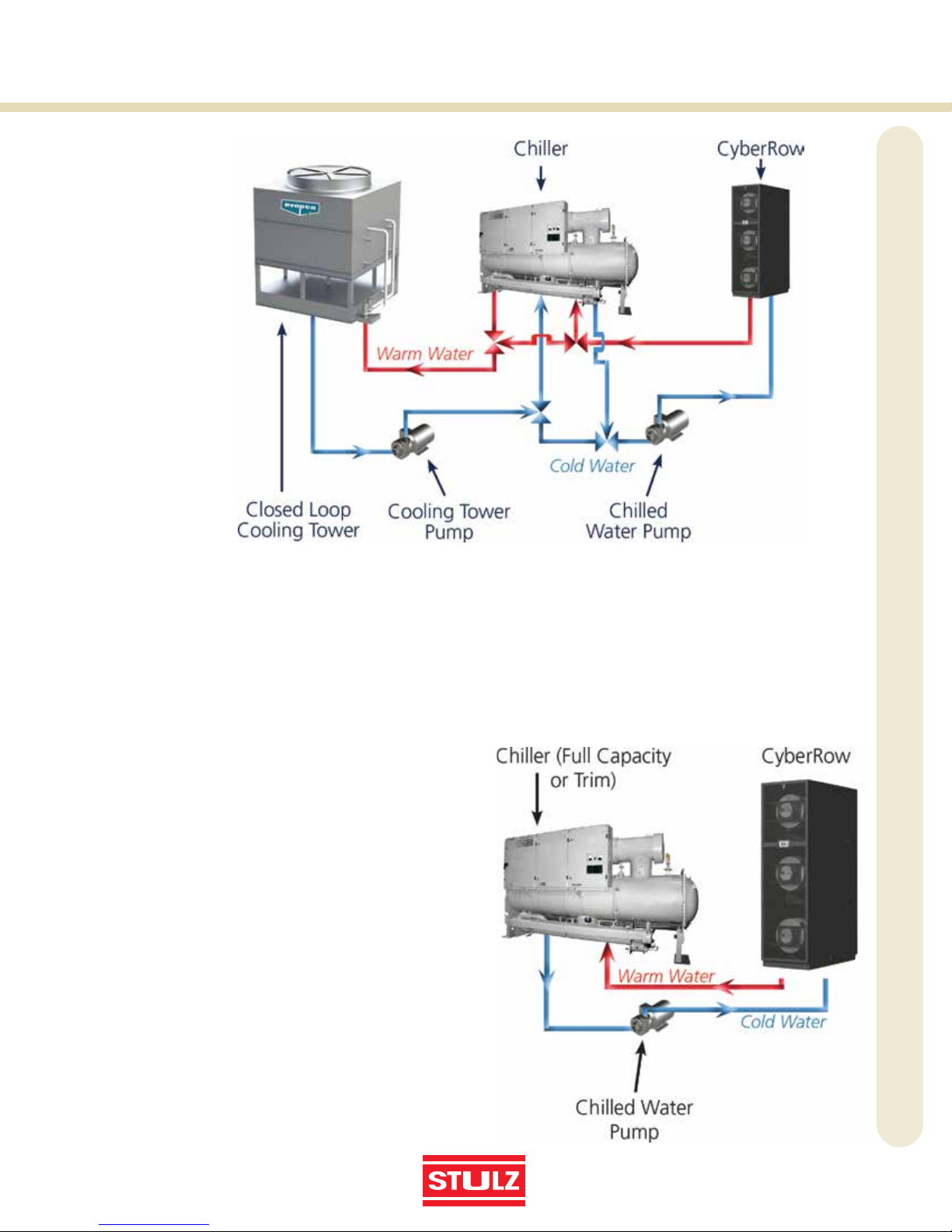
Chilled Water System
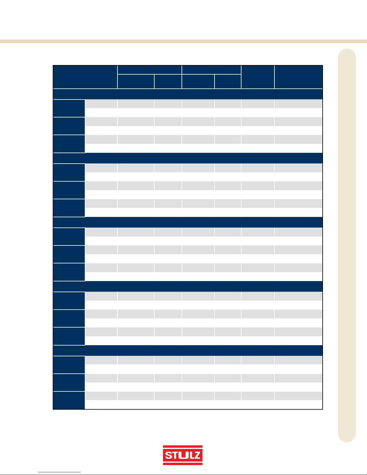
24” Chilled Water
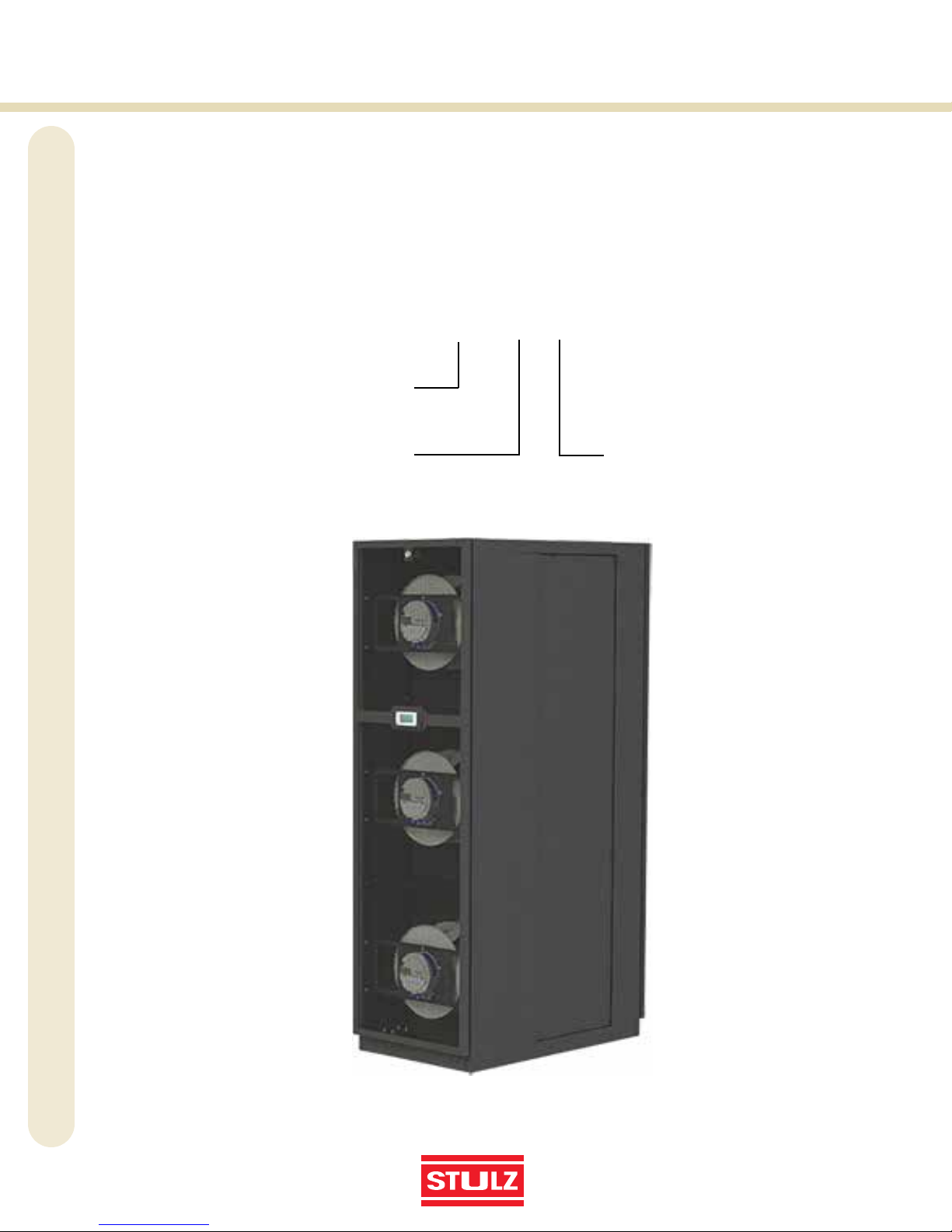
CRS-180-C
Total Capacity Sensible Capacity Flow Rate
GPM
Total System
Pressure Drop,
Ft. H2O
BTU/H kW BTU/H kW
100˚FDB/ 69.2˚FWB Entering Air Temperature
40˚F EWT 10˚F ∆T 270,762 79.4 267,158 78.3 56.0 55.2
12˚F ∆T 252,610 74.0 252,610 74.0 43.5 34.3
45˚F EWT 10˚F ∆T 235,275 69.0 235,275 69.0 49.0 42.6
12˚F ∆T 228,040 66.8 228,040 66.8 39.5 28.4
50˚F EWT 10˚F ∆T 210,435 61.7 210,435 61.7 44.0 34.5
12˚F ∆T 203,363 59.6 203,363 59.6 35.5 23.1
95˚FDB/67.7˚FWB Entering Air Temperature
40˚F EWT 10˚F ∆T 245,849 72.1 239,969 70.3 51.0 46.4
12˚F ∆T 239,974 70.3 235,218 68.9 41.5 31.5
45˚F EWT 10˚F ∆T 209,408 61.4 209,408 61.4 43.5 34.1
12˚F ∆T 202,307 59.3 202,307 59.3 35.2 22.9
50˚F EWT 10˚F ∆T 184,879 54.2 184,879 54.2 39.0 27.6
12˚F ∆T 177,574 52.0 177,574 52.0 31.2 18.1
90˚FDB/66.1˚FWB Entering Air Temperature
40˚F EWT 10˚F ∆T 220,747 64.7 212,936 62.4 46.0 38.2
12˚F ∆T 214,208 62.8 207,808 60.9 37.0 25.4
45˚F EWT 10˚F ∆T 183,826 53.9 183,826 53.9 38.5 27.1
12˚F ∆T 176,252 51.7 176,252 51.7 31.0 18.1
50˚F EWT 10˚F ∆T 158,847 46.6 158,847 46.6 33.5 20.7
12˚F ∆T 151,093 44.3 151,093 44.3 26.7 13.5
85˚FDB/64.5˚FWB Entering Air Temperature
40˚F EWT 10˚F ∆T 195,763 57.4 185,634 54.4 41.0 30.8
12˚F ∆T 188,714 55.3 180,359 52.9 33.0 20.5
45˚F EWT 10˚F ∆T 158,051 46.3 158,051 46.3 33.5 20.9
12˚F ∆T 149,579 43.8 149,579 43.8 26.5 13.5
50˚F EWT 10˚F ∆T 132,979 39.0 132,979 39.0 28.5 15.3
12˚F ∆T 124,153 36.4 124,153 36.4 22.2 9.6
80˚FDB/62.8˚FWB Entering Air Temperature
40˚F EWT 10˚F ∆T 170,522 50.0 158,384 46.4 36.0 24.2
12˚F ∆T 162,601 47.7 152,689 44.8 28.5 15.6
45˚F EWT 10˚F ∆T 131,334 38.5 131,334 38.5 28.0 15.0
12˚F ∆T 122,660 35.9 122,660 35.9 22.0 9.5
50˚F EWT 10˚F ∆T 105,995 31.1 105,995 31.1 23.0 10.3
12˚F ∆T 96,888 28.4 96,888 28.4 17.7 6.3
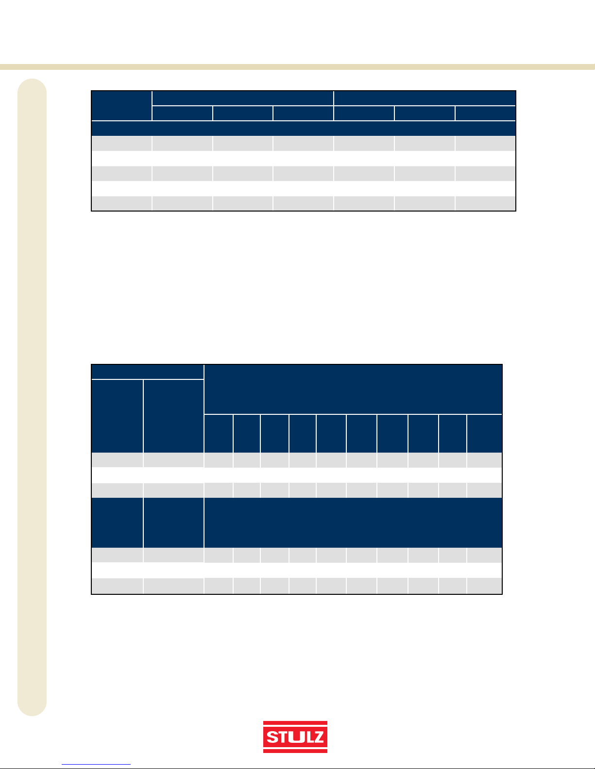
PERFORMANCE DATA