Style selections TPGAZ2236 User manual

SOFT TOP GAZEBO
ITEM #5106736
MODEL #TPGAZ2236
Français p. 20
STYLE SELECTIONS and logo design are
trademarks or registered trademarks of LF, LLC.
All rights reserved.
Questions, problems, missing parts? Before returning to your retailer, call our
customer service department at
877-888-8225, 8 a.m. - 8 a.m., EST, Monday - Sunday.
AK24010
ATTACH YOUR RECEIPT HERE
Serial Number ___________
Purchase Date ___________
1234567
8 9 10 11 12 13 14
15 16 17 18 19 20 21
22 23 24 25 26 27 28
29 30 31 32 33 34 35
36 37 38

TABLE OF CONTENTS
Package Contents ........................................................................................................................ 3
Hardware Contents ...................................................................................................................... 4
Safety Information ........................................................................................................................ 5
Preparation .................................................................................................................................. 5
Installation Instructions.................................................................................................................. 6
Care and Maintenance ................................................................................................................ 19
Warranty ....................................................................................................................................... 19
Replacement Parts List ............................................................................................................... 19
1234567
8 9 10 11 12 13 14
15 16 17 18 19 20 21
22 23 24 25 26 27 28
29 30 31 32 33 34 35
36 37 38

PART DESCRIPTION QUANTITY PART DESCRIPTION QUANTITY
A
B1
B2
2
4
2
2
2
4
2
2
2
1
1
1
4
1
1
2
B3
B4 2
C 6
D 8
F1
4E1
4E2
4
G1
4
H
I
J
K
L1
L2
L3
M
N
O
P
F2
Center Connector
PACKAGE CONTENTS
A
N
P
O
A
A
A
E1 E1
GF1
B1
G1
G2
G2
B2
B4 F2
B3
E2
E2
E1
E1
B1
B2
G
F1
E2
F2
B4
B3
ML1
K
KH
H
I
I
J
L2
L3
E2
lenaP
Long Cross Beam L
Short Cross Beam L
Short Cross Beam R
Long Cross Beam R
Mosquito Net Tube
Mosquito Net Tube
Beam Connector
Beam Connector
Left oblique suppoort
4
G2 Right oblique support
4
GU-connector Small Canopy
Big Canopy
Sidewall
Top Support
Top Support
Top Support
Small top tube
Small top support
Top Support
Connector
Hook
Ornament
D
D
D
D
D
D
C
C
C
C
1234567
8 9 10 11 12 13 14
15 16 17 18 19 20 21
22 23 24 25 26 27 28
29 30 31 32 33 34 35
36 37 38

M6 × 25 mm Bolt
Qty. 4 + 1 Extra M6 × 28 mm Bolt
Qty. 6 + 1 Extra
Qty. 12 + 2 Extra
Cap
Cap Qty. 88 + 5 Extra
Qty. 36 + 2 Extra
Screw Nut
Qty. 12 + 2 Extra
Wrench
Qty. 2
tloBmm51×6M
Qty. 68 + 2 Extra
tloBmm51×6M
Qty. 4 + 1 Extra
Washer
Plastic Ring
Connectors
Qty. 104 + 6 Extra
Plastic Washer
Qty. 8 + 1 Extra
AA CC EE
GG
BB FF
OO
LL
JJ KK
II
Stake
Qty. 8
HARDWARE CONTENTS
( NOT TO SCALE)
HH
MM NN
M6 × 35 mm Bolt
Qty. 8+ 1 Extra
DD
M6 × 32 mm Bolt
Qty. 2 Extra
QQ
PP
Allen Wrench
Qty. 1
M8 Washer
Qty. 1
M8 Nut
Qty. 1
1234567
8 9 10 11 12 13 14
15 16 17 18 19 20 21
22 23 24 25 26 27 28
29 30 31 32 33 34 35
36 37 38

SAFETY INFORMATION
A
PREPARATION
Please read and understand this entire manual before attempting to assemble, operate or install
the product.
WARNING
• Maximum load for the roof hook: 26 lbs.
• WARNING: KEEP ALL FLAME AND HEAT SOURCES AWAY FROM THIS TENT FABRIC.
The fabric may burn if left in continuous contact with any flame source. The application of any
foreign substance to the tent fabric may render the flame-resistant properties ineffective.
CAUTION
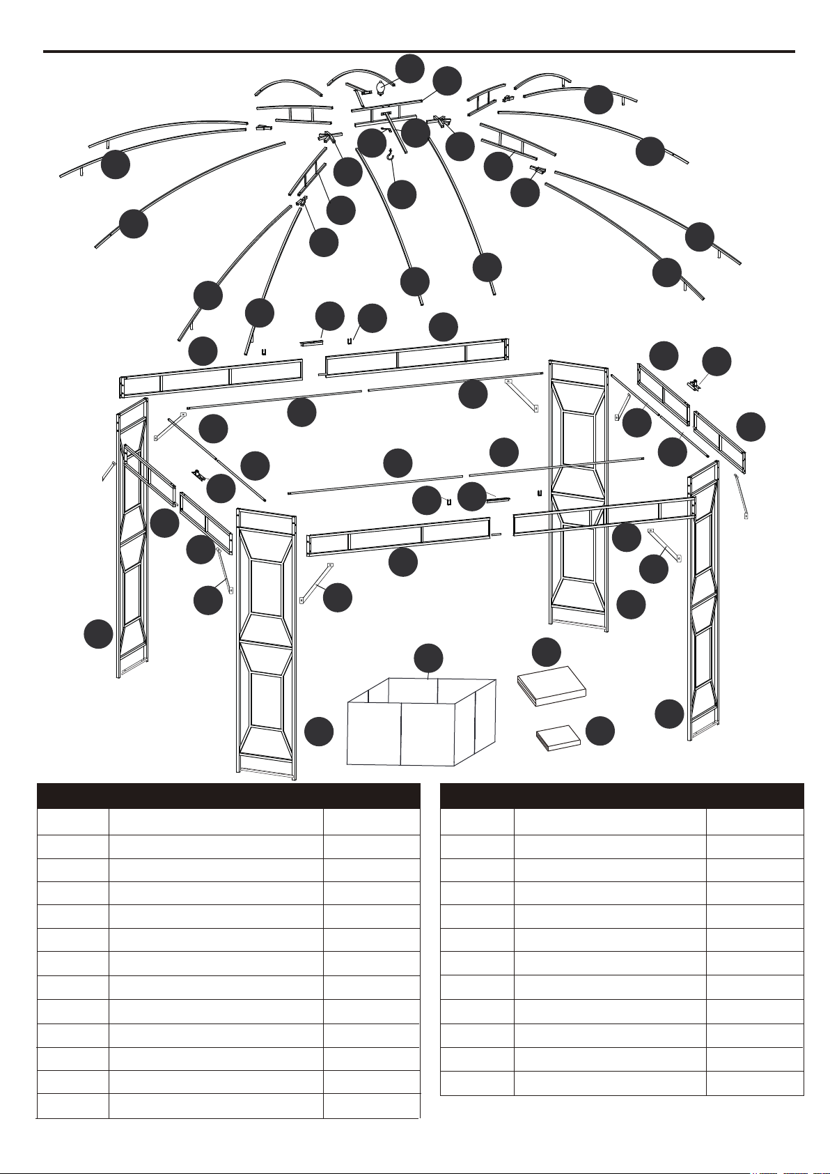
Before beginning assembly of product, make sure all parts are present. Compare parts with package
contents list and hardware contents list. If any part is missing or damaged, do not attempt to
assemble the product.
Estimated Assembly Time: 40 minutes
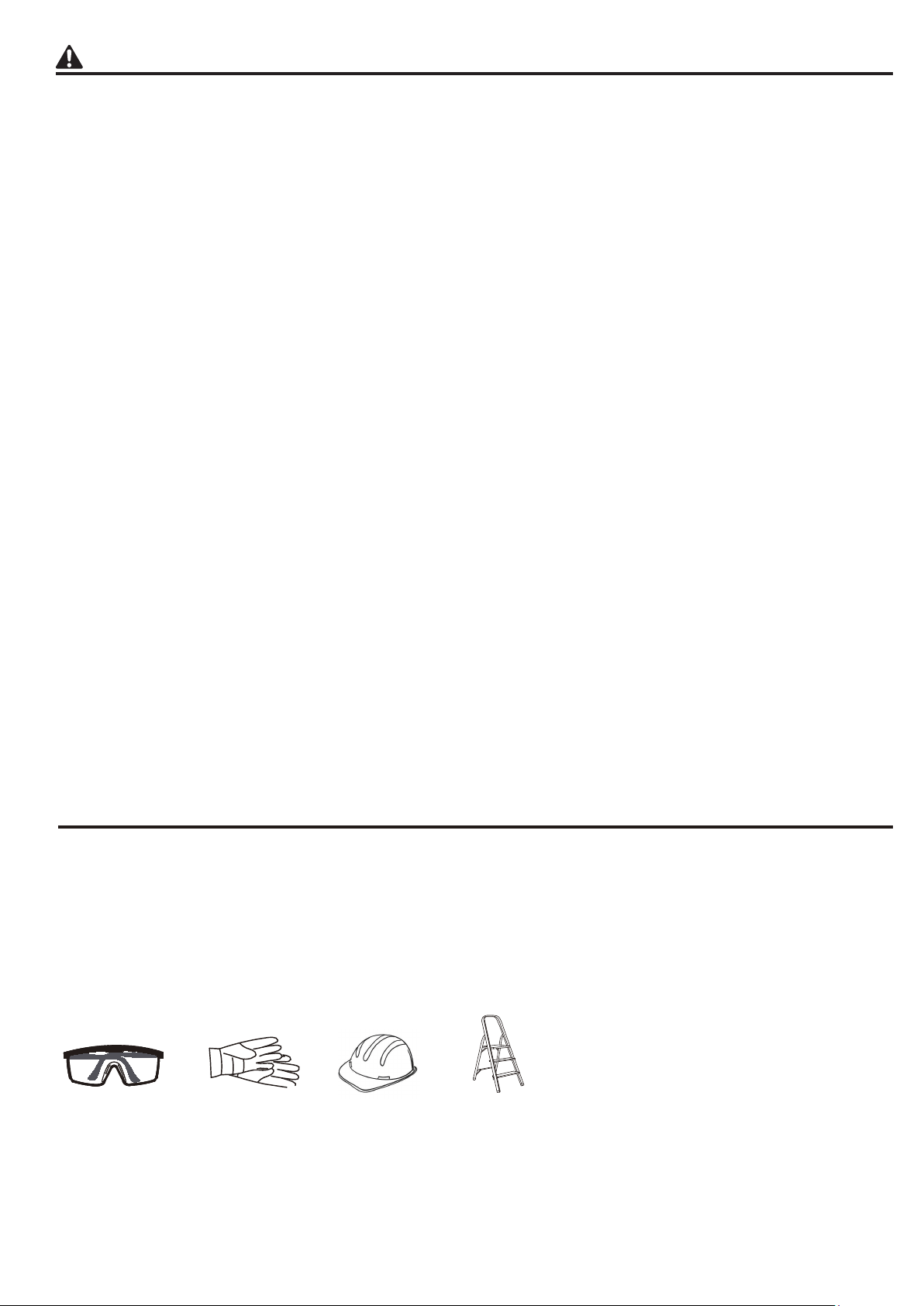
Tools Required for Assembly (not included): Safety goggles, Gloves, Hardhat, Stepladder.
SET UP YOUR GAZEBO PROPERLY
• 4 people are recommended for safe assembly.
• Keep all children, pets and other obstructions away from assembly area.
• If any part is missing or damaged, do not attempt to assemble the product.
• In order to avoid damage to the gazebo and its components please use appropriate tools.
• Do not use the structure as support.
• Check all bolts on a regular basis to maintain the solidity of the structure.
• Keep instructions for future use.
• Do not climb on top of the gazebo. Falling off the gazebo can result in serious injury,
possibly even death.
EXAMINE YOUR GAZEBO
• Examine occasionally to ensure there are no loose parts.
If loose parts are found, they should be retightened immediately.
• If high winds, heavy rains or any snow occurs, remove roof
and curtain,
and check for damage before continued use.
Safety goggles
Gloves Stepladder
Hard hat
1234567
8 9 10 11 12 13 14
15 16 17 18 19 20 21
22 23 24 25 26 27 28
29 30 31 32 33 34 35
36 37 38

1.1 Connect long cross beam L (B1) and the long cross beam R (B2), then connect them by bolt (BB) / (FF) /
(II) and tighten them by using wrench (JJ). Place cap (HH) on the bolt heads and cap (GG)
on the Nut.
1.2 Connect the beam connector (F1) onto the cross beams (B1/B2) by bolt (AA) / (FF) and tighten them
with wrench (JJ). Install the U-connector (G) onto the cross beams (B1/B2) by bolt (EE) / (FF) and tighten
them with allen wrench (LL). Place cap (HH) on the bolt heads.
Repeat the step for another assembly.
x10
x16
x2
BB
FF
JJ
INSTALLATION INSTRUCTIONS
x1
LL
x4
x10
HH
x2
II
x2
GG
EE
B1
B1
HH BB FF FF II GG
B2
B2
B1
F1
F1
EE
FF
EE
FF
HH
AA
FF
B1 B2
G
G
GG
B2
1Hardware Used
1234567
8 9 10 11 12 13 14
15 16 17 18 19 20 21
22 23 24 25 26 27 28
29 30 31 32 33 34 35
36 37 38

2.1 Connect the short cross beam L (B3) and the short cross beam R (B4) by bolt (BB) / (FF) / (II), then
tighten them with wrench (JJ). Place cap (HH) on the bolt heads and cap (GG) on the nut.
2.2 Connect the beam connector (F2) with the cross beams (B3/B4) by bolt (AA) / (FF) , then tighten
them with wrench (JJ). Place cap (HH) on the bolt heads .
Repeat the step for another assembly.
B3
B3
B4
B4
HH BB FF FF II GG
B3
F2
F2
HH
AA
FF
B4
x2
x12
x2
BB
FF
JJ
x8
x10
HH
x2
II
x2
GG
AA
INSTALLATION INSTRUCTIONS
2Hardware Used
1234567
8 9 10 11 12 13 14
15 16 17 18 19 20 21
22 23 24 25 26 27 28
29 30 31 32 33 34 35
36 37 38

3. Connect the assembled (B1/B2) with the panel (A) by bolt (AA) / (FF), then tighten them with wrench (JJ).
Place cap (HH) on the bolt heads.
Repeat the step for another assembly.
A
FF
AA
HH
FF AA HH
B1 B2
B2
B1
B1
B2
A
A
A
A
INSTALLATION INSTRUCTIONS
3Hardware Used
x16
x16
AA
FF
x1
JJ
x16
HH
1234567
8 9 10 11 12 13 14
15 16 17 18 19 20 21
22 23 24 25 26 27 28
29 30 31 32 33 34 35
36 37 38

B2
B1
B4
B3
A
A
AA
B1
B2
B4
B3
4. Connect the assembled (B3/B4) with the panel (A) by bolt (AA) / (FF), then tighten them with wrench (JJ).
Place cap (HH) on the bolt heads.
Repeat the step for another assembly.
AFF
AA
HH
FF AA HH
B3 B4
B1
B2
INSTALLATION INSTRUCTIONS
4Hardware Used
x16
x16
AA
FF
x1
JJ
x16
HH
1234567
89 10 11 12 13 14
15 16 17 18 19 20 21
22 23 24 25 26 27 28
29 30 31 32 33 34 35
36 37 38

5.1 Connect oblique support (G1/G2) to the beam (B1 / B4), with bolt (AA/FF). Then tighten them with
wrench (JJ). Place cap (HH) on the bolt heads.
5.2 Connect oblique support(G1/G2) to the beam (B2/B3), with Bolt (AA/FF). Then tighten them with
wrench (JJ). Place cap (HH) on the bolt heads.
Repeat the step for another assembly.
FF
FF
G1
G1
G1
G1
G1
B1 B4
G2
G2
G2
G2
G2
AA
AA
HH
HH
FF
FF
G1
B3 B2
G2
AA
AA
HH
HH
INSTALLATION INSTRUCTIONS
5Hardware Used
x16
x16
AA
FF
x1
JJ
x16
HH
1234567
8 9 10 11 12 13 14
15 16 17 18 19 20 21
22 23 24 25 26 27 28
29 30 31 32 33 34 35
36 37 38

6.1 Insert one end of the mosquito net tube (E1) into the beam connector (F1), pass the mosquito net (E1)
through the spacer block (NN) to connect the other end onto the cross beams (B1/B2) with bolt (DD/FF).
Then tighten them with wrench (JJ). Place cap (HH) onthe bolt heads.
6.2 Insert one end of the mosquito net tube (E2) into the beam connector (F2), pass the mosquito net (E2)
through the spacer block (NN) to connect the other end onto the cross beams (B3/B4) with bolt (DD/FF).
Then tighten them with wrench (JJ). Place cap (HH) on the bolt heads.
Repeat the step for another assembly.
DD HH
JJ
NN
FF
B1
B2
B1 B2
F1
F1
F2 F2
F2
F1
E1
E2
B3
B4
B3
B4 E2
E2
E1 E1
E2
E2
E1
E1 FF
DD
HH
NN
B2B1
E1
E2 FF
DD
HH
NN
B3B4
x8
x8
INSTALLATION INSTRUCTIONS
x8
x1
x8
6Hardware Used
1234567
8 9 10 11 12 13 14
15 16 17 18 19 20 21
22 23 24 25 26 27 28
29 30 31 32 33 34 35
36 37 38

7.1 Insert two center connectors (K) into top support (L1) and secure with a bolt (AA/FF). Then tighten them
with wrench (JJ). Place cap (HH) on the bolt heads.
7.2 Pass the connector (I) through the top support (H), then pass the two top supports (D) to the connector (I),
spring clip connected.
Repeat the step for another assembly.
L1
K
FF
AA
HH
FF
AA
HH
K
D
D
H
I
IH
D
D
INSTALLATION INSTRUCTIONS
7Hardware Used
x2
x2
AA
FF
x1
JJ
x2
HH
1234567
8 9 10 11 12 13 14
15 16 17 18 19 20 21
22 23 24 25 26 27 28
29 30 31 32 33 34 35
36 37 38

H
K
A
K
HH
H
K
H
8. Insert the Top support (H) into the center connector (K), then insert the top support (D) into the
panel (A), spring clip connected.
Repeat the step for another assembly.
D
D
INSTALLATION INSTRUCTIONS
8
DD
A
1234567
8 9 10 11 12 13 14
15 16 17 18 19 20 21
22 23 24 25 26 27 28
29 30 31 32 33 34 35
36 37 38

9. Insert one end of the Top Support (C) into the Center Connector (K), spring clip connected. Connect
the other end onto the U-connector (G) and Beam Connector (F2) by Bolt (CC/FF/II). Tighten them with
the Wrench (JJ). Place cap (HH) on the bolt heads and cap (GG) on the Nut.
CC
C
C
CC
B1
B2
B1 B2
B4
B3
B4
B3
C
C
C
CC
C
K K
B4
BB
HH CC FF
GG
II
FF
B3 B2
B1
II
HH
CC FF
C
C
G
F2
GG
II
FF
x6
x12
x2
CC
FF
JJ
x6
HH
x6
II
x6
GG
INSTALLATION INSTRUCTIONS
9Hardware Used
1234567
8 9 10 11 12 13 14
15 16 17 18 19 20 21
22 23 24 25 26 27 28
29 30 31 32 33 34 35
36 37 38

10.1 Connect two small top tubed (L2) to the Top Support (L1) and secure with bolts (QQ/FF/II).Then tighten
them with wrench (JJ). Place cap (HH) on the bolt heads and cap (GG) on the Nut.
10.2 Connect one end of the two small top supports (L3) to the small top tube (L2), secure with bolt (AA/FF)
and the other with top support (L1) with Hook (J) and screw nut (OO) and washer (PP).Then tighten them
with wrench (JJ).
Place cap (HH) on the bolt heads.
QQ
HH
JJ
II
FF
x2
x2
x6 x1
AA
x1
PP
L1
L2
L2
L2
HH
HH
HH
AA
AA
FF
FF
L2
J
J
L3
L3
L3
OO PP
L3
L3
L2
QQ
FF
FF
QQ
HH
GG
GG
II
II
FF
FF
x2
x4
x2
GG OO
x1
INSTALLATION INSTRUCTIONS
10 Hardware Used
1234567
8 9 10 11 12 13 14
15 16 17 18 19 20 21
22 23 24 25 26 27 28
29 30 31 32 33 34 35
36 37 38

11. Install the Big Canopy (O) over the top frame without stretching and fix it first. Cover the Small Canopy (P)
onto the Top Support (H), then pass the Ornament (M) through the Small Canopy (P) to connect it onto the
Top Support (L1).
P
M
O
P
M
L1
INSTALLATION INSTRUCTIONS
11
O
H
P
1234567
8 9 10 11 12 13 14
15 16 17 18 19 20 21
22 23 24 25 26 27 28
29 30 31 32 33 34 35
36 37 38

x36
MM
INSTALLATION INSTRUCTIONS
P
O
O
O
D
C
12.1 Stretch the Small Canopy (P) and connect it with the Top Support (H), then fully stretch the Big Canopy (O)
onto the whole top frame, insert the Top Supports (C/D) into the corner pocket of the big canopy in it's four
corners.
12.2 Insert the Plastic Ring Connectors (MM) into the Sidewall (N) and connect it with the mosquito net
tubes (E1/E2), tie the sidewall up tightly around the post panels by the felt of the sidewalls.
M
S
N
S
N
S
O
E1 E2
S
MM
S
MM
S
MM
S
E2
S
E1
S
A
*5
*4
A
12 Hardware Used
1234567
8 9 10 11 12 13 14
15 16 17 18 19 20 21
22 23 24 25 26 27 28
29 30 31 32 33 34 35
36 37 38

KK KK
x8
KK
13. Insert the Stake (KK) into the Panel (A) to fix the gazebo.
A
A
INSTALLATION INSTRUCTIONS
13 Hardware Used
1234567
8 9 10 11 12 13 14
15 16 17 18 19 20 21
22 23 24 25 26 27 28
29 30 31 32 33 34 35
36 37 38

CARE AND MAINTENANCE
WARRANTY
• WHAT IS NOT COVERED
We do not reimburse for transportation costs. This warranty does not cover the damage caused by commercial
use, acts of nature, fire, freezing, and abusive use. Discoloration or fading of the finish or fabrics as a result
of chemicals or spills is not covered.
Contact the Customer Service Team at 877-888-8225.
•For cleaning, use a mild detergent solution, rinse with water, and allow to air dry.
Do not use acetone, abrasive, or other special detergents as they would be harmful to the product’s finish.
•Due to the nature of steel, surface oxidation (rusting) will occur if this protective coating is scratched.
This is a natural process. To minimize this condition, it is recommended that care be taken when assembling
and handling the product in order to prevent the paint from being scratched.
REPLACEMENT PARTS LIST
For replacement parts, call our customer service department at 877-888-8225, 8 a.m. - 8 p.m., EST,
Printed in China
AA CC EE
GG
BB FF
II
HH MM NN
DD
PART DESCRIPTION PART #
AA 2
M6 x 15 mm Bolt
M6 x 15 mm Bolt
BB 1
M6 x 25 mm Bolt
CC 1
M6 x 28 mm Bolt
DD 1
M6 x 35 mm Bolt
EE 1
Washer
FF 6
GG 2
HH 5
II 2
MM 2
NN 1
PART DESCRIPTION PART #
Cap
Cap
Screw Nut
Plastic Ring Connectors
Plastic Washer
1 YEAR WARRANTY FOR FRAME AND FABRIC.
•WHAT IS COVERED
We provide warranty to the original purchase for 1 year for frame and fabric from the date of
purchase, and the fabric and frame will be replaced at no charge due to manufacturing defects.
1234567
8 9 10 11 12 13 14
15 16 17 18 19 20 21
22 23 24 25 26 27 28
29 30 31 32 33 34 35
36 37 38

GAZEBO DE
CUBIERTA SUAVE
OLUCÍTRA #5106736
MODELO #TPGAZ2236
STYLE SELECTIONS y el diseño del logotipo son
marcas comerciales o marcas registradas de LF, LLC.
Todos los derechos reservados.
ADJUNTE EL RECIBO AQUÍ
Número de serie ___________
Fecha de compra ___________
¿Preguntas, problemas, piezas faltantes? Antes de volver a la tienda, llame a
nuestro Departamento de Servicio al Cliente al 877-888-8225, de lunes a domingo
de 8 a.m. a 8 p.m., hora estándar del Este. También puede ponerse en contacto
1234567
8 9 10 11 12 13 14
15 16 17 18 19 20 21
22 23 24 25 26 27 28
29 30 31 32 33 34 35
36 37 38
This manual suits for next models
1
Table of contents
Languages:
Other Style selections Outdoor Furnishing manuals
Popular Outdoor Furnishing manuals by other brands

Hanover
Hanover NEWPORT6PCNVY installation guide

for Living
for Living 088-1613-8 Assembly instructions

Crivit
Crivit 280890 Instructions for use

Backyard Discovery
Backyard Discovery ARLINGTON 2206106 manual

Hanover
Hanover Fontana FNTDN7PCRDTN manual

Royal garden
Royal garden FCS70438RSTRGDS Use and care guide

eDecks
eDecks Step Stringer Handrail Fitting instructions

Casa Nico
Casa Nico 48 INCH PATIO CABINET Instruction booklet

World Market
World Market Sevilla 551907 Assembly instructions

Extremis
Extremis MARINA PICNIC Assembly instructions

Island Umbrella
Island Umbrella NUP30332 manual

Hanover
Hanover FTA30348 Assembly instructions