STYLEX Still Screens User manual

1
Still Screens Assembly Instructions
Parts and Hardware Overview
Base Riser
H3
1/4”-20 Thread x 1”
3/8” Hex Head
H4
#10-32 Thread x 5/8”
Phillips Pan Head
Baseboard End-CoverScreen ConnectorBase Plate Base Connector
H6
Leveling Glide
3/8” Hex Head
H5
#10-32 Thread x 7/16”
Phillips Pan Head
H2
Leveling Screw
3/8” Hex Head
H1
#10-32 Thread x 1/2”
Phillips Flat Head
Parts
Hardware
Safety Glasses
3/8” Wrench
3/8” Socket and Ratchet
#2 Phillips Screwdriver, 6” length
1/4” Flat-head Screwdriver
Table or Stands
*2 person assembly requirement
Tools & Equipment Required

2
Still Screens Assembly Instructions
Baseplate Attachment
Assemble the Baseplate to the Baseplate Riser using the 4 Philips head screws
provided (H1). Typically, the direction of the riser and plate should match the
diagram (See Image A). However, the direction of the Base Riser may be reversed
to allow height adjustment if the hex screws (H3) are difficult to access while the
screen is positioned. The point of the center hole of the baseplate should face the
edge of the screen.
To install the Baseplate assembly on a screen, place the screen on an elevated
flat surface; the end of the screen receiving the baseplate should be on the left-
hand side of the installer. (See Image C)
Baseplate Assembly and Installation
Assembly Steps Standard Direction (Image A)
1. Thread the Leveling Screw (H2) into the Base Riser until it stops.
2. Align the Leveling Screw (H2) into the slot of the Baseplate Connector.
3. Use the two hex head screws (H3) to fasten the Base Riser to the Base
Connector, and tighten with a 3/8” socket and ratchet.
Assembly Steps Opposite Direction (Image B)
1. Place the leveling screw in the slot in the Base Connector and position the
baseplate riser, aligned with the leveling screw.
2. Rotate the Leveling Screw, threading it into the Baseplate Riser until it stops.
3. Install the two hex head screws and tighten with a 3/8” socket and ratchet.
Image A
figure C
Standard Direction Baseplate Assembly
figure B Opposite Direction Baseplate Assembly
H1 x 4
H2
H3 x 2
With a partner, pick up the screen and stand it up on the floor. Do not
lean the screen on the edge of the baseplate.
H1 x 4
H3 x 2
H2
Base Plate
Base Riser
Base Connector
H1 #10-32 Thread x 1/2” Phillips Flat Head
H2 Leveling Screw 3/8” Hex Head
H3 1/4”-20 Thread x 1” 3/8” Hex Head
Parts Required
Safety glasses
3/8” Wrench
3/8” Socket and Ratchet
#2 Phillips Screwdriver, 6” length
Tools Required
H2
3
Still Screens
Screen Connector (Pre-Installed)
H4 #10-32 Thread x 5/8”Phillips Pan Head
H6 Leveling Glide 3/8” Hex Head
Assembly Instructions
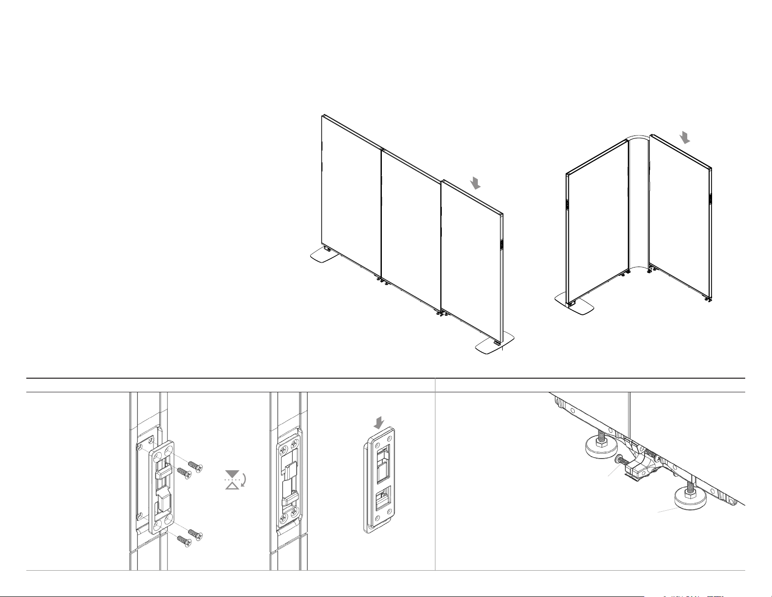
Screen to Screen Assembly
Do not assemble screens while laying flat, or lay assembled screen groups on the
floor.
1. For linear assemblies, installation should begin with one end of a layout (Image
A). If the layout has corners, begin with installation with one of the corners
(Image B). Ensure that the first screen is placed accurately within the room
before assembly the layout.
Note: If dual fabric screens are included, ensure textiles are facing the correct
side. If power is included in the system, ensure that receptacle brackets are
oriented in the correct direction.
2. The hook of the Upper Connector on an installed screen should face upqard,
while the connector on the screen to be installed should face downward. Follow
diretions in Detail A to flip upper connectors.
3. Position the next screen where it will be connected. Slightly lift the screen,
engage the upper connectors, and lower the screen (see Detail A below for
further instructions). If required, use a clean mallet or dead blow hammer to tap
the screen downward and fully engage.
4. Follow directions in Detail B to fasten and level each screen together.
5. When the layout is safely freestanding and with no more that 3 screens, double
check the screen locations within the room, and move if necessary. Do not move
assemblies of more than 3 screens.
When assembling larger layouts or when floors are irregular, it may be necessary to
raise all of the screens in order to allow for the adjust-ability to make all connections.
If glides cannot be adjusted high enough to account for irregularities, shims may be
installed underneath glides. Shims should not be used under Baseplates.
Assembling Layouts & Connecting Screens
Detail A : Upper Connector Detail B : Base Connector Assembly
The direction of the
Upper Connector may
be flipped by removing
the four Phillips screws,
rotating, and reinstalling
the screws.
Image A Image B
Check that adjacent base
connectors are aligned before
installing screws. Do not force
alignment by installing screws
on an angle.
If necessary, raise or lower
each screen by rotating the
glides (H6) with a 3/8” wrench
or adjust the height of a
baseplate by loosening the two
hex screws (H3), adjusting the
leveling screw (H2) with a 3/8”
wrench, and re-tightening the
hex screws (H3).
To complete assembly, install
the (H4) screws with a long
Phillips screwdriver, 2 in each
direction (4 total for each
screen connection).
flip
If corner screens are in the layout, start assembly with a
corner screen.
Start assembly at end of run.
H6 x 2
H4 x 4
Parts Required
Safety glasses
#2 Phillips Screwdriver, 6” length
Tools Required

4
Still Screens
When installing an Endcap
Screen, check that the
upper connector on the
screen that the Endcap will
connect to is facing upward
(reference Detail A on pg. 3).
Hook the Endcap onto the
screen and lower it. Align
the attached Baseboard
End-Cover with the Base
Connector and secure the
screen by installing two
(H5) screws with a long
Phillips screwdriver.
Assembly Instructions
Baseboard Covers
1. Endcap Screen Installation (Includes integrated End-Cover) 2. Baseboard End-Cover Installation 3. Baseboard Assembly
Corners Screens:
Install Corner curved baseboards by
hooking one end onto the pins and rotating
into place until the magnet holds the cover.
Alignment of the baseboard may be
adjusted by turning the magnet catch
screw clockwise or counter clockwise.
Straight Screens:
Install straight screen baseboards by
hooking the top of the baseboard onto the
Base Connectors and Baseboard Hangers
then rotating downward until the clips hold
it in place.
The spring clips can be adjusted by slightly
bending. Bend the clip upward to allow
the baseboard to rotate into place or
downward to increase the holding force on
the baseboard.
Once assembled, check that all baseplates and glides are making firm
contact with the floor. Adjust if necessary. Tighten all Baseplate hex
screws (H3, reference pg. 2).
Once the assembly is completely level and screens are tightly fastened
together, begin installation of Endcap Screens, Baseboard End-Covers,
and Basebaord components by following the detailed instructions
below.
Leveling, End-Covers, and Basebaords
Align the holes of the
End-Cover with the
Base Connector and
secure by installing
two 7/16” screws (H5)
with a long Phillips
screwdriver.
Screen Connector (Pre-Installed)
H5 #10-32 Thread x 7/16” Phillips Pan Head
Parts Required
Safety glasses
#2 Phillips Screwdriver, 6” length
Tools Required
Other STYLEX Indoor Furnishing manuals

STYLEX
STYLEX Mark 2 Installation instructions

STYLEX
STYLEX Still User manual

STYLEX
STYLEX Verve Installation instructions

STYLEX
STYLEX Zephyr Installation instructions

STYLEX
STYLEX Metrum Installation instructions

STYLEX
STYLEX F4 Installation instructions

STYLEX
STYLEX Bounce Installation instructions

STYLEX
STYLEX Welcome Installation instructions
Popular Indoor Furnishing manuals by other brands

Regency
Regency LWMS3015 Assembly instructions

Furniture of America
Furniture of America CM7751C Assembly instructions

Safavieh Furniture
Safavieh Furniture Estella CNS5731 manual

PLACES OF STYLE
PLACES OF STYLE Ovalfuss Assembly instruction

Trasman
Trasman 1138 Bo1 Assembly manual

Costway
Costway JV10856 manual


