STYLEX Still User manual

1
Still Screens
Safety Glasses
#2 Phillips Screwdriver, 6” length
Wire Ties
Tools & Equipment Required
Parts & Sub-Assemblies
H5
#10-32 Thread x 7/16”
Phillips Pan Head
Hardware
HW1
#8-16 Thread
Phillips #2 Pan Head
Thread Forming Screw for Plastic
HW2
#6-19 Thread
Phillips #2 Round Head
Thread Forming Screw for Plastic
Jumper Corded (End) Infeed Sub-Assembly Hardwired (Side) Infeed Sub-Assembly
Receptacle Duplex Receptacle USB Receptacle Bracket Receptacle Connector H-Connector Hanger
All components should be installed with the “4-TRAC” logo facing
upright.
Power components needs to be installed after all screens in the layout
are fully assembled and adjusted, before installing Baseboards, End
Covers, and End Caps.
General Information
Power Assembly Instructions
Parts and Hardware Overview
2
Still Screens
Receptacle
Jumpers
Receptacle Bracket (Pre-Installed)
Receptacle Connector
H-Connector
Hanger (Pre-Installed)
Parts Required
Safety glasses
Wire Ties
Tools Required
Image A
Image B
Image C
Image D
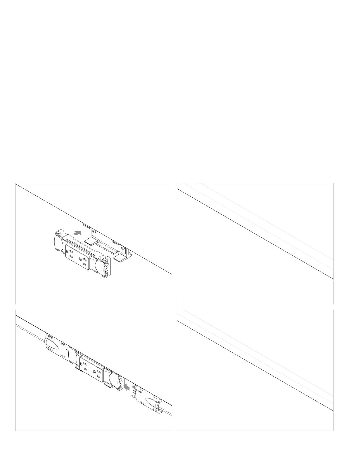
Receptacles (Image A)
1. Snap Receptacles into the Receptacle Bracket
Splits Without a Receptacle (Image C)
1. When a split is located in a screen without a receptacle, install an
H-Connector on a baseboard Hanger by looping a wire tie through
the hanger and wrapping around the center of the H-Connector.
Splits With a Receptacle (Image D)
1. Connect a Receptacle Connector to the Receptacle in the direction
of the split.
2. Connect an H-Connector to the Receptacle Connector.
Assembly Steps for Receptacle, Jumper, and Split Installation
Power Assembly Instructions
Receptacles / Jumpers / Splits
All components should be installed with the “4-TRAC” logo facing
upright.
Power components needs to be installed after all screens in the layout
are fully assembled and adjusted, before installing Baseboards, End
Covers, and End Caps.
General Information
Jumpers (Images B, C, D & following page E, F, G)
1. Connect Receptacles and splits using jumpers. Take care to use the
correct jumper length for each location in the layout. (Images B, C,
and D)
2. Use wire ties through the small holes in Base Connectors to attach
jumpers (following page Image E).
3. Route jumpers through corners and use wire ties to attach to corner
glides (following page Image G).
4. When routing through a screen without power, jumpers may be wire
tied to holes in receptacle brackets (following page Image F).
Do not fully tighten or clip wire ties until the power system is complete
and the baseboards have been test-fit.

3
Still Screens
Image G
Image E Image F
Power Assembly Instructions
Receptacles / Jumpers / Splits

4
Still Screens
1. Connect the Corded Infeed to the indicated receptacle.
2. Route the conduit to the end of the layout.
3. Position the Conduit Clamp inboard of the Base Connector (see Image A
callout where the cord meets conduit).
4. Wire tie the cord to the Base Connector. Do not fully tighten or clip wire ties
until the power system is complete and the baseboards have been test-fit.
5. Install a Baseboard End-Cover or an Endcap Screen with an H5 Screw.
Wire Tie Locations
H5 Screw
Conduit Clamp
Corded (End) Infeed Assembly and Installation
Corded (End) Infeed Sub-Assembly
3-Pronged Jumper
Conduit Clamp
Baseboard End-Cover (or Endcap Screen) with Infeed Cutout
H5 #10-32 Thread x 7/16” Phillips Pan Head
Parts Required
Safety glasses
Wire Ties
#2 Phillips Screwdriver, 6” length
Tools Required
Power Assembly Instructions
Corded Infeed

5
Still Screens
Image A
Image B
Image C
Hardwired (Side) Infeed Sub-Assembly
Hardwire Body Receptacle
Pivot Block x2
Conduit with Clip
Baseboard Cover with Receptacle Cutout
Hardwire Cover
HW1 #8-16 Thread Phillips #2 Pan Head Thread Forming Screw for Plastic x4
HW2 #6-19 Thread Phillips #2 Round Head Thread Forming Screw for Plastic x2
Parts Required
Safety glasses
#2 Phillips Screwdriver, 6” length
Tools Required
Power Assembly Instructions
Hardwired Infeed
1. Remove the two Pivot Blocks from the Hardwire Body Receptacle by removing
the 4 HW1 screws and sliding the Pivot Blocks apart. (See Image A)
2. Clip the Hardwire Body Receptacle into the indicated screens Receptacle
Bracket. (See Image B)
3. Connect the Baseboard Cover that includes a Receptacle Cutout by:
a. Hook the top of the baseboard onto the Base Connectors and Baseboard
Hangers. (Image D)
b. Rotate downward until the clips hold in place. (Image D)
c. Spring clip may be adjusted by slightly bending. Bend the clip upward to
allow the baseboard to rotate into place or downward to increase the holding
force on the baseboard. (Image E)
4. Continue onto next page.
Hardwired (Side) Infeed Assembly and Installation
Image D Image E
Other STYLEX Indoor Furnishing manuals

STYLEX
STYLEX Bounce Installation instructions

STYLEX
STYLEX Verve Installation instructions

STYLEX
STYLEX Metrum Installation instructions

STYLEX
STYLEX Mark 2 Installation instructions

STYLEX
STYLEX Zephyr Installation instructions

STYLEX
STYLEX F4 Installation instructions

STYLEX
STYLEX Still Screens User manual

STYLEX
STYLEX Welcome Installation instructions
Popular Indoor Furnishing manuals by other brands

Regency
Regency LWMS3015 Assembly instructions

Furniture of America
Furniture of America CM7751C Assembly instructions

Safavieh Furniture
Safavieh Furniture Estella CNS5731 manual

PLACES OF STYLE
PLACES OF STYLE Ovalfuss Assembly instruction

Trasman
Trasman 1138 Bo1 Assembly manual

Costway
Costway JV10856 manual


