✓
FA-200
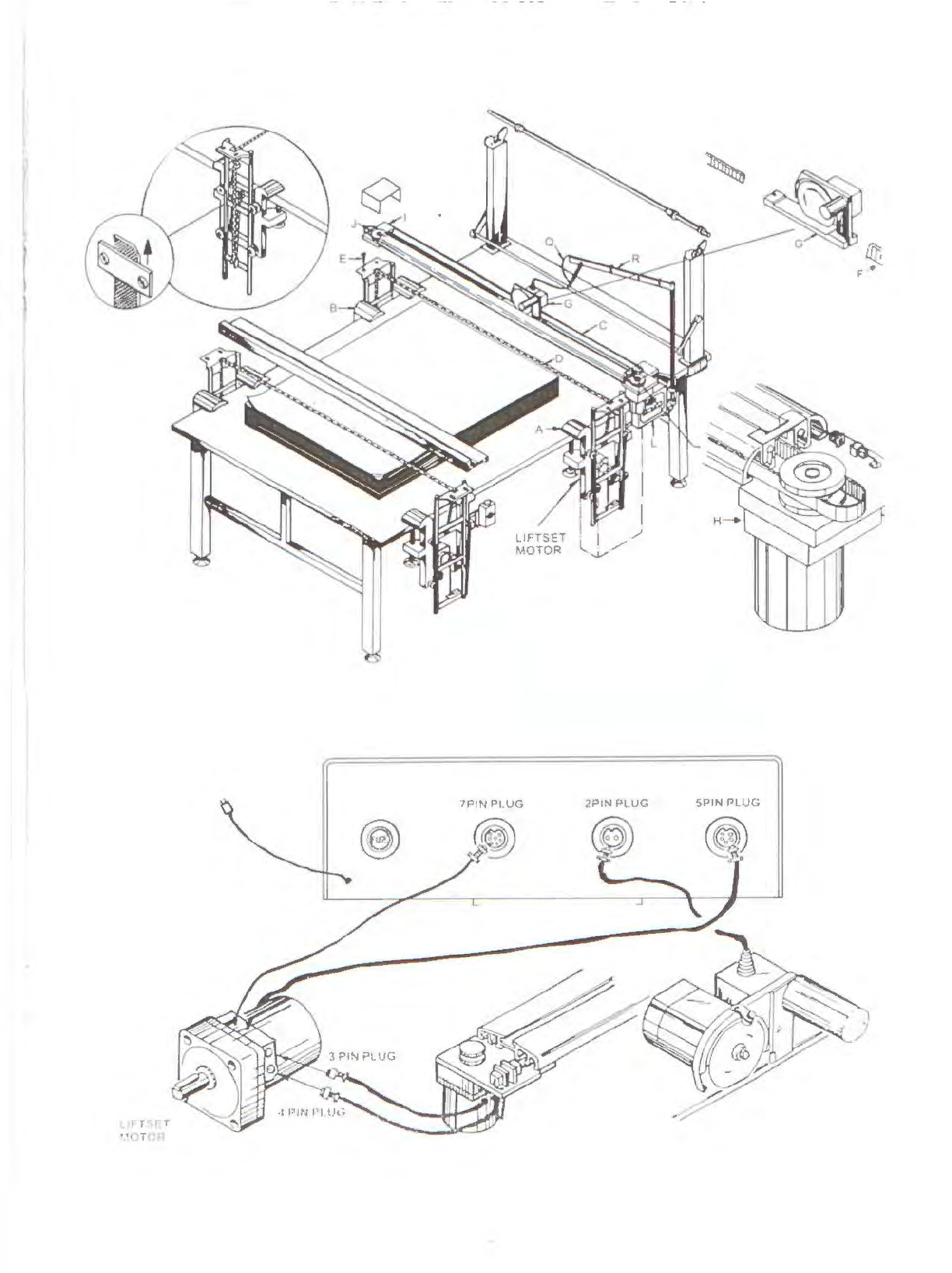
INSTALLATION
INSTRUCTION
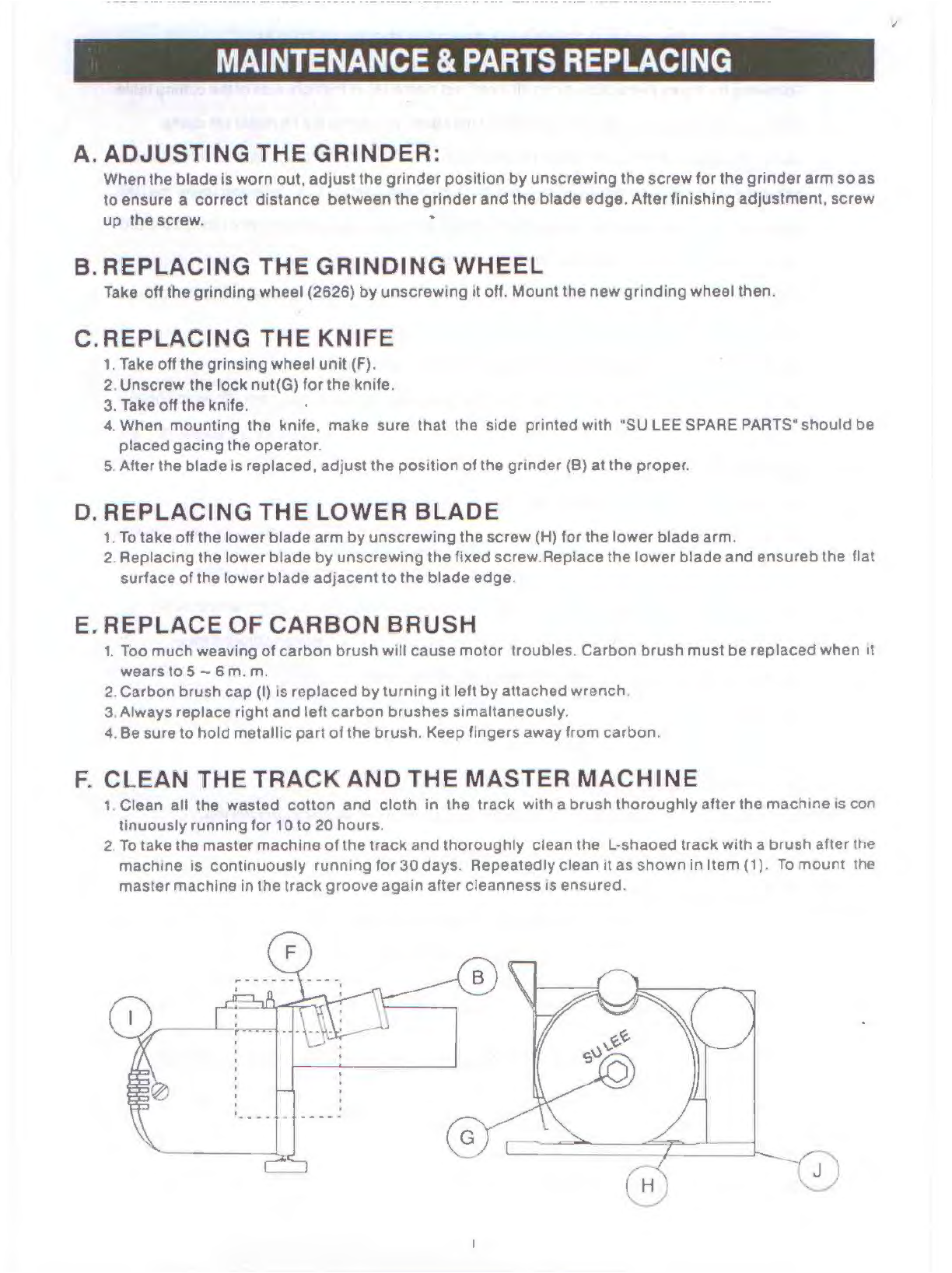
1. Following
the
figure instruction, fixing
lift
motor
set
clamp
(A)
at
the rightside
of
thecutting table.
2.
Fixing anotherset clamp (B}
at
the left
side
of
thetableoppos,teto the lift motorset clamp.
3.
Fasten fistone end
of
the LIFT BELT ,nto
the
BELT PRESS PIECE
of
the CLAMP ASSEMBLY and
allow the other end to pass through ttte ROLLER
of
theBAR LIFTER, crossing under the RAIL
thread through the ROLLER
of
the BAR LIFTER, then throughthe DOWN ROLLER
on
the BAR
LIFTER finally tinghten
it
in
theBELT PRESS PIECE.
4. Place rail (C) onto lift rod. Note: The end with powerline
out
shoutd
be
placed at thelift
motor
set
clampside.
5. Fasten
both
ends
of
the rail (C) onto theliftrod with setscrews
(E)
.
6. Hook the gear
bell
hook
(F)
from bottom upward
onto
the rear side. Put cutter (G) insiderail (C).
7. FixTransmission
motor
assembly (H)
at
the power line
out
end
with rail fixing screw (E). and
connector the
two
plugs.
8. Fixbeltpulley (I)
at
the
other
end
of
rail with rail fixing screw(E).
9. Wmd the other end
of
beltacross transmissiongear(H). through bottom
of
therail (C),
up
to the
opposite
side
belt pulley,back toinside
of
rail (C), then
hook
on
to the front
of
cutter.
(Note: Inspect the belt, make sure
it
Isnot twisted, otherwiseitwillendanger theoperation)
10. AdJust gearbelt
by
means
of
belt adjusting screw (J)
lo
a suitable tension (about5 mm)
11
. Installcontrol box frame (K)
and
place control box(L) onto it.
12. Installation of wiringbracket:
a. Fixingset
clamp
(M)
at
cutting table.
b. Installwi,ing
pipe
(N) and supporting bracket
(0)
.
c. Lead twin hole electricwire
(0)
through wiring
pipe
(R)
downward from the
top
d. Install receptaclereserve suitableend length, then fix
it
with binding belt.
13. Installationof fabricsupporting rack:
a. Fix fabric supporting rack to
both
sides
of
the cutting table.
b. Install leverrespectively to the two fabric supporting rack.
c. Insertthe Iron
lube
.
d. Place
on
the fabric supportrod to finish the installation.
14
. Insert three wiresrespectively twinholes. five holes. and seven holes rnto the receptacles
underneathcontrol
box
(L).