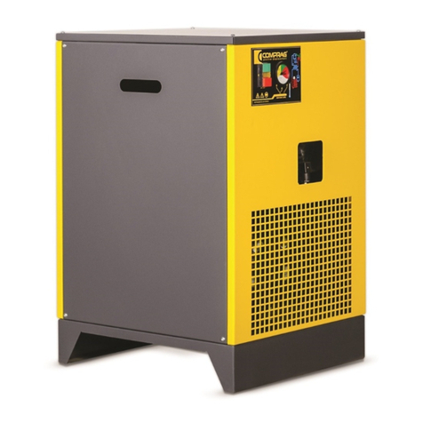
Sullair SRC User manual

Service Manual
for the
SRC Cycling Refrigerated
Air Dryers
Document PN#: 02250___-___

SRC Service Manual
Revision 02
Aug 2007
Table of Contents
1. General Description 4
2. Specifications 5
2.1 Model Range 5
2.2 Operating Limits 5
2.3 Technical Specifications 6
2.4 Weight & Dimensions 7
3. System Design 8
3.1 The Air Circuit 9
3.1.1 Air-To-Air Heat Exchanger 10
3.1.2 Air-To-Coolant Heat Exchanger 10
3.1.3 Demister Separator 10
3.1.4 Condensate Chamber 10
3.1.5 Dew Point Temperature Sensor 11
3.1.6 Level Sensor 11
3.2 The Coolant Circuit 11
3.2.1 The Thermal Mass Concept 12
3.2.2 Coolant-to-Refrigerant Heat Exchanger 13
3.2.3 Coolant Tank 14
3.2.4 Coolant Pump 14
3.2.5 Coolant Pressure Relief Valve 15
3.2.6 Coolant Expansion Tank 15
3.3 Refrigeration Circuit 15
3.3.1 Compressor 16
3.3.2 Condenser & Fan 16
3.3.3 Refrigerant Filter 17
3.3.4 Expansion Device 17
3.3.5 Refrigerant 17
3.3.6 High Pressure Switch 18
3.3.6 Low Pressure Switch 18
3.3.7 Fan Pressure Switch 18
3.4 Physical Arrangements 19
3.4.1 SRC-150 to 200 19
3.4.2 SRC-250 to 500 19
3.4.3 SRC-700 to 1000 20
(Continued on following page…)
Page 1 of 56

SRC Service Manual
Revision 02
Aug 2007
4. Control System 21
4.1 Power Supply 21
4.2 Controls on the SRC-150 to 200 21
4.3 Controls on the SRC-250 to 1000 22
4.3.1 Inputs 22
4.3.2 Outputs 23
4.3.3 Specifications 23
4.3.4 User Interface 23
4.3.4.1 Lights 24
4.3.4.2 Buttons 25
5. Installation 26
6. Start Up 28
7. Operation & Control (SRC-250 to 1000) 29
7.1 Turning the Dryer On or Off 29
7.2 User Parameter List 30
7.3 Accessing & Modifying User Parameters 31
7.4 Factory Parameter List 32
8. Cycling Operation 33
8.1 SRC-150 to 200 33
8.2 SRC-250 to 1000 33
9. Condensate Drain Operation 35
9.1 SRC-150 to 200 35
9.2 SRC-250 to 325 35
9.3 SRC-400 to 1000 35
9.4 Drain Operating Mode (Parameter D3) 37
9.5 Manual Drain Activation 37
10. Alarms & Warnings 38
10.1 Alarm & Warning List 38
10.2 Troubleshooting Alarms & Warnings 39
10.2.1 HP - High Pressure (Alarm) 39
10.2.2 LP - Low Pressure (Alarm) 40
10.2.3 Ld - Low Dewpoint (Alarm) 41
10.2.4 rSE - Coolant Temperature Sensor Error (Alarm) 42
10.2.5 Hd - High Dewpoint (Warning) 42
10.2.6 drE - Drain Error (Warning) 44
10.2.7 dSE - Dewpoint Sensor Error (Warning) 45
10.2.8 Sr - Service Required (Warning) 45
(Continued on following page…)
Page 2 of 56

SRC Service Manual
Revision 02
Aug 2007
10.3 Service Required Warning (Sr) 46
10.3.1 How to Reset the Service Required (Sr) Warning 46
10.3.2 How to Change the Service Required (Sr) Warning Interval 47
10.4 Alarm History Report 48
10.5 Remote Monitoring Option 49
11. Recommended Maintenance 50
11.1 Maintenance Schedule 50
11.2 Preventative Maintenance Kits 50
12. Maintenance Procedures 51
12.1 Replacing a Pressure Switch 51
12.2 Replacing the Thermostat (SRC-150 to 200) 51
12.3 Replacing the Control Board (SRC-250 to 1000) 52
12.4 Replacing the Drain Valve 52
12.5 Cleaning the Condensate Strainer 53
12.6 Replacing the Coolant Pump 53
13. Confirming Dryer Sizing 55
13.1 Correction Factors 55
13.2 An Example 56
Page 3 of 56

SRC Service Manual
Revision 02
Aug 2007
1. General Description
The SRC Cycling Refrigerated Air Dryer reduces the dew point
(1)
of compressed air stream by reducing the temperature causing
water and oil vapour (along with other evaporated contaminants)
to condense into a liquid. These liquids are then separated from
the air and discharged from the system. The dry air is then re-
heated before continuing downstream.
Air streams are measured in terms of their flow, temperature and
pressure. These variables fluctuate continuously throughout the
day and can change drastically throughout the year, depending
on the climate, conditions, and application. As they change, so
does the amount of heat in the air (called the “heat load”) and
therefore the amount of moisture the air stream can carry.
Every refrigerated air dryer is designed to handle a maximum
incoming heat load. At any heat load below the maximum, there
is the potential for saving energy as the dryer is absorbing less
heat, that it is designed for.
The SRC is a “cycling” dryer, because it reduces it’s power
consumption at reduced heat loads by cooling the air using a large tank of a cold glycol & water
mixture (referred to as a thermal mass), which is in turn cooled by a refrigeration system. When there
is less heat load, the thermal mass absorbs less heat, and the refrigerant system is cycled on and off
only as necessary to keep the thermal mass cold. This absorbs less energy than traditional non-
cycling dryers which do not use a thermal mass, and therefore must run their refrigeration system
continuously all the time.
(1) Dew point – a measurement of the amount of moisture in a gas, indicated as the temperature at which
the air would be saturated (i.e. the relative humidity would be 100%) and liquid condensate would begin
to form. It is commonly shown as
o
F or
o
C. It is important when discussing dew point to specify if you are
referring to the “pressure dew point” (the dew point at the pressure of the system) or “atmospheric dew
point” (the dew point at atmospheric pressure) as the two are significantly different.
Page 4 of 56

SRC Service Manual
Revision 02
Aug 2007
2. Specifications
2.1 Model Range
Rated
Flow* Port Size
Model Volt Ph Hz (scfm) (NPT-F)
02250 165 - 492 115
02250 165 - 493 230
SRC-175 02250 165 - 494 230 1 60 175 1-1/2"
SRC-200 02250 165 - 495 230 1 60 200 1-1/2"
02250 165 - 496 1
02250 165 - 497
02250 165 - 498 460
02250 165 - 500 575
02250 165 - 501 1
02250 165 - 502
02250 165 - 503 460
02250 165 - 504 575
02250 165 - 506 230
02250 165 - 507 460
02250 165 - 508 575
02250 165 - 510 230
02250 165 - 511 460
02250 165 - 512 575
02250 165 - 513 230
02250 165 - 514 460
02250 165 - 515 575
02250 165 - 516 460 3
02250 165 - 517 575
02250 165 - 518 460 3
02250 165 - 519 575
* Maximum rated flow at 100 deg F (38 deg C) & 100 psig (7 bar g) inlet, 100 deg F (38 deg C) ambient.
Frame
Size Compressor
Type
Compliant
Scroll
1-1/2"
3"
3"
3"
2"
2"
1-1/2"60
60 250
325
60
60 850
1000
SRC-400
SRC-325
SRC-250
SRC-1000
SRC-850
SRC-700
SRC-500
Control
Type Expansion
Device
Capillary
Tube
2Micro-
processor
Part #
Sullair
1-1/2"
Voltage
SRC-150 150
700
3Thermostatic
Valve
400
500
160 AnalogPiston1
3
3
3
60
60
60
3
3
230
230
2.2 Operating Limits
Operating Limit Minimum Rated Maximum*
Ambient Temperature: 41
o
F 5
o
C 100
o
F 38
o
C 113
o
F 45
o
C
Inlet Temperature: 41
o
F 5
o
C 100
o
F 38
o
C 140
o
F 60
o
C
Inlet Pressure: 60 psig 4 bar g 100 psig 7 bar g 203 psig 14 bar g
* Maximum allowable working pressures may vary with location depending on local pressure vessel design regulations.
Page 5 of 56

SRC Service Manual
Revision 02
Aug 2007
2.3 Technical Specifications
SRC-150 SRC-175 SRC-200 SRC-250 SRC-325
Type
Charge 1.76 lbs (0.8 kg)
Internal Diameter 0.072" (1.83 mm)
Length 66.9" (1700 mm)
Min 23°F (-5°C)
Max
Min
Max
Coolant Type
Min
Max
Coolant Tank Capacity
High Pressure Switch Setting
On
Off
Total Absorbed Power at Full Rated Load 1.44 kW 1.54 kW 1.70 kW 2.66 kW 2.80 kW
Min
Max
Min
Max
Min 5.5A6.3A7.6A
Max 6.7A7.5A9.2A
Pressure Drop at Full Rated Load 1.8 psid 2.3 psid 3.0 psid 2.0 psid 3.3 psid
SRC-400 SRC-500 SRC-700 SRC-850 SRC-1000
Type
Charge 7.05 lbs (3.2 kg)
Internal Diameter
Length
Type TLEX 4.5
Setting (# of turns) 9.5
Min
Max 44.6°F (7°C)
Min
Max
Coolant Type
Min
Max
Coolant Tank Capacity
High Pressure Switch Setting
On
Off
Total Absorbed Power at Full Rated Load 3.35 kW 3.41 kW 5.24 kW 6.10 kW 6.58 kW
Min
Max
Min
Max
Min 5.5 A
Max 6.7 A
Pressure Drop at Full Rated Load 1.1 psid 1.8 psid 0.9 psid 1.3 psid 1.6 psid
42% Glycol, 58% Water (Freezing Point -13F)
R407C 3.97 lbs (1.8 kg)
Refrigerant
Capillary Tube
Coolant Temperature (at tank outlet)
Discharge Temperature
Suction Temperature
Fan Pressure Switch
Coolant Pump Power Consumption
Fan Power Consumption
Compressor Power Consumption 8.3 A
1.3 A
1.1 A
0.77 A
0.63 A
0.13 A
6.9 A
0.57 A0.15 A
50°F (10°C)
113°F (45°C)
34.7°F (1.5°C)
0.47 A
42% Glycol, 58% Water (Freezing Point -13F) 140°F (60°C)143.6°F (62°C)
122°F (50°C)
406 psig (28 bar g)
38.3°F (3.5°C)39.2°F (4°C)
33.8°F (1°C)
13.2 gal (50 L)7.13 gal (27 L)
Refrigerant R407C
5.07 lbs (2.3 kg) 12.8 lbs (5.8 kg)
Capillary Tube 0.098" (2.5 mm)
51.2" (1300 mm)
Thermostatic Valve TLEX 5
8
Suction Temperature 28.4°F (-2°C) 32°F (0°C)
50°F (10°C) 50°F (10°C)
Discharge Temperature 118.4°F (48°C) 122°F (50°C)
145.4°F (63°C) 140°F (60°C)
Coolant Temperature (at tank outlet) 34.7°F (1.5°C)
38.3°F (3.5°C)
13.2 gal (50 L) 27.7 gal (105 L)
406 psig (28 bar g)
Fan Pressure Switch 261 psig (18 bar g)
203 psig (14 bar g)
Coolant Pump Power Consumption 1.1 A 1.0 A
1.3 A 1.2 A
Fan Power Consumption 0.47 A 1.2 A
0.57 A 1.4 A
Compressor Power Consumption 6.9 A 8.4 A
8.3 A 10.2 A
203 psig (14 bar g)
261 psig (18 bar g)
2.43 lbs (1.1 kg) 0.098" (2.5 mm)0.085" (2.16 mm)
98.4" (2500 mm) 51.2" (1300 mm)
44.6°F (7°C) 28.4°F (-2°C)19.4°F (-7°C)
Page 6 of 56

SRC Service Manual
Revision 02
Aug 2007
2.4 Weight & Dimensions
SRC-150 to 200 SRC-250 to 500 SRC-700 to 1000
A
BCWei
g
ht
in (mm) in (mm) in (mm) lbs (kg)
SRC-150 28.5
(
723
)
42.5
(
1080
)
32.5
(
826
)
322
(
146
)
SRC-175 28.5
(
723
)
42.5
(
1080
)
32.5
(
826
)
335
(
152
)
SRC-200 28.5 (723) 42.5 (1080) 32.5 (826) 335 (152)
SRC-250 29.0
(
737
)
52.1
(
1323
)
42.3
(
1074
)
562
(
255
)
SRC-325 29.0 (737) 52.1 (1323) 42.3 (1074) 562 (255)
SRC-400 29.0
(
737
)
52.1
(
1323
)
42.3
(
1074
)
591
(
268
)
SRC-500 29.0 (737) 52.1 (1323) 42.3 (1074) 591 (268)
SRC-700 29.0
(
737
)
72.6
(
1844
)
55.3
(
1405
)
895
(
406
)
SRC-850 29.0 (737) 72.6 (1844) 55.3 (1405) 970 (440)
SRC-1000 29.0 (737) 72.6 (1844) 55.3 (1405) 970 (440)
Model
Page 7 of 56

SRC Service Manual
Revision 02
Aug 2007
3. System Design
The SRC dryer consists of three circuits from right to left: The Air Circuit, the Coolant Circuit, and the
Refrigeration Circuit:
J
I
H G
F
E
D C
B
A
•The Air Circuit: Consisting primarily of:
A. Air-to-Air heat Exchanger,
B. Air-to-Coolant Heat Exchanger,
C. Slowflow Demister Separator, and
D. Condensate Chamber
The air enters the dryer and passes through the Air-to-Air Heat Exchanger (A) where it is
cooled by the outgoing air. The air then passes through the Air-to-Coolant Heat Exchanger (B)
where it is further cooled by the coolant. The air then passes through the Slowflow Demister
Separator (C) where the condensate is separated from the air. The condensate collects in the
Condensate Chamber (D), before being discharged from the system by a condensate drain
(not shown). The air passes back through the Air-to-Air Heat Exchanger where it is reheated
by the incoming air before leaving the dryer.
•The Coolant Circuit: Consisting primarily of:
B. Air-to-Coolant Heat Exchanger,
E. Coolant-to-Refrigerant Heat Exchanger, and
F. Coolant Re-circulation Pump.
The coolant passes through the Air-to-Coolant Heat Exchanger (B) where it absorbs heat from
the air. It then passes through the Coolant-to-Refrigerant Heat Exchanger where it is cooled
by the refrigerant, and flows into the Coolant Tank. It is re-circulated continuously by the
Coolant Re-circulation Pump (F).
(Continued on following page…)
Page 8 of 56

SRC Service Manual
Revision 02
Aug 2007
•The Refrigeration Circuit: Consisting primarily of:
E. Coolant-to-Refrigerant Heat Exchanger,
G. Refrigerant Compressor,
H. Condenser,
I. Refrigerant Filter, and
J. Expansion Device.
The refrigerant passes through the Coolant-to-Refrigerant Heat Exchanger (E) where it
absorbs heat from the coolant causing it to evaporates into a gas. It then passes through the
Refrigerant Compressor (G) where it is compressed causing it to heat up. It then passes
through the Condenser (H) where it is cooled by the ambient air (using a fan) and condenses
back into a liquid. It them passes through the Refrigerant Filter (I) where any impurities are
removed. It then passes through the Expansion Device (J) where it is expanded.
3.1 The Air Circuit
The SRC is unique in that it’s entire air circuit is combined into a single compact 4-in-1 unit,
combining:
•the Air-to-Air Heat Exchanger,
•the Air-to-Coolant Heat Exchanger,
•a Slowflow Demister Separator, and
•a Condensate Chamber.
into a single component (patent pending).
This combined component performs the functions
of cooling the incoming air to the desired
temperature (using first the cold outgoing air, and
then the coolant), as well as separating the liquid
form the air stream, and collecting the
condensate to drain it from the system*.
A
B
C
The Air-to-Air and Air-to-Coolant heat exchangers are an aluminium fin design, which combine high
surface area (and therefore efficient heat transfer) with low pressure drop and minimum corrosion.
The air circuit is insulated with special TSI Thermal Shield Insulation (polystyrene based) offering a
very high thermal retention for even further improved efficiency. D
There are two control devices in the Air Circuit
•the Dew Point temperature Sensor, and
•the Level Sensor*.
* SRC-400 to 1000 only – see Section 9 for further information.
Page 9 of 56

SRC Service Manual
Revision 02
Aug 2007
3.1.1 Air-to-Air Heat Exchanger
An Air-to-Air Heat Exchanger is an aluminium fin, cross flow exchanger. The Air-to-Air Heat
Exchanger is also often called a “Pre-cooler / Re-heater” because the hot air entering the dryer is pre-
cooled by the cold air exiting the dryer; while at the same time the cold air exiting the dryer is re-
heated by the hot air entering. Then end result is that the pre-cooling offers a significantly reduced
heat load on the cooling circuit (which offers notable energy savings), and the re-heating offers
elimination of condensation accumulation on the downstream air piping, as well as increasing the
temperature of the air, keeping it well away from the dew point. The air leaving the dryer is
approximately 10 degrees cooler than the air coming in.
3.1.2 Air-to-Coolant Heat Exchanger
An Air-to-Coolant Heat Exchanger is an aluminium fin, counter flow
exchanger. Here, the air (having been already pre-cooled in the Air-
to-Air Heat Exchanger), is further cooled by the coolant mixture. This
Heat Exchanger is part of both the air and coolant circuits.
3.1.3 Demister Separator
All models are equipped with a Slowflow demister type moisture
separator to remove the condensed liquids from the compressed air.
The liquid droplets impact the stainless steel fibers of the demister, and coalesce into larger drops
where they are pulled into the Condensate chamber by gravity.
The demister combines a high efficiency with a low pressure drop. It is significantly larger than
standard demisters (typically at least four times as large) and as such the air velocity across it is much
slower. In addition, the Slowflow design provides increased contact time allowing high separation
efficiency. The Slowflow demister separator guarantees perfect operation at all air flows, unlike
centrifugal separators which quickly lose efficiency at lower air flows, and standard demisters which
lose efficiency at higher air flows.
Once separated the condensate is removed from the air circuit by the condensate drain. The dry, cold
air then passes through the “re-heating” side of the air-to-air exchanger.
3.1.4 Condensate Chamber
Condensate is collected in the condensate chamber before being discharged from the system through
the Condensate Drain.
Page 10 of 56

SRC Service Manual
Revision 02
Aug 2007
3.1.5 Dew Point Temperature Sensor
All models have a Dew Point Temperature Sensor that measures the temperature of the air leaving
the Air-to-Coolant Heat Exchanger. At this point in the dryer, the temperature of the air equals the dew
point.
On the SRC-150 to 200 this controls the color Dew Point Indicator on the top of the dryer. On the
SRC-250 to 1000, this is the dew point temperature which is shown on the digital display during
normal operation.
3.1.6 Level Sensor
The SRC-400 through 1000 have a Level Sensor in the Condensate Chamber. This sensor sends a
signal to the microprocessor when the level of condensate reaches it, which then opens the
Condensate Drain Valve. Details of Condensate Drain Operation are covered in Section 9.
3.2 The Coolant Circuit
The Coolant Circuit consists of the Air-to-Coolant Heat Exchanger (described in 3.1.2 above) as well
as the Coolant-to-Refrigerant Heat Exchanger (which is mounted inside the Coolant Tank) and the
Coolant Re-circulation Pump.
The Coolant Circuit is pre-filled and pressurized* with a 58%Water / 42% Glycol coolant mixture with a
freezing point of approximately -13
o
F (-25
o
C), which is continuously circulated by the Coolant Pump.
A Coolant Pressure Relief Valve protects the system from over-pressure*, and a Coolant Expansion
Tank allows expansion and contraction of the coolant with changes in temperature.
* The maximum allowable working pressure of the Coolant Circuit is 87 psig. Maximum allowable working
pressures may vary with location depending on local pressure vessel design regulations.
Page 11 of 56

SRC Service Manual
Revision 02
Aug 2007
3.2.1 The Thermal Mass Concept
The purpose of the Coolant Circuit is to provide a dynamic “Thermal Mass” – that is a moving mass of
material with high thermal retention – or the capacity to absorb a significant quantity of heat without a
rapid rise in temperature.
The Thermal Mass consists of more than just the Coolant. All components of the system add to it’s
capacity to absorb heat, including:
•the Coolant,
•the Coolant-to Refrigerant Heat Exchanger,
•The Air-to-Coolant Heat Exchanger,
•the Coolant Tank,
•the inter-connecting piping of the coolant circuit, and
•the Coolant Re-circulation Pump.
As the Coolant absorbs heat from the air, it disperses this heat throughout the Coolant Circuit, and
due to the significant mass of cold material to absorb this heat, the temperature rises very slowly.
The controls of the SRC dryer monitor the temperature of the Coolant in the Coolant Tank, and allow it
to fluctuate between an upper and lower limit.
When the temperature of the Coolant reaches the upper limit it turns the Refrigerant Compressor on,
and the resulting cooling effect in the Coolant-to-Refrigerant heat Exchanger, brings the Coolant
Temperature down.
When the temperature of the Coolant reaches the lower limit it turns the Refrigerant Compressor off,
and it’s temperature begins to rise again*.
The less the heat load in the incoming air, the less heat is transferred to the Coolant, the slower the
temperature rises, the less the refrigerant compressor needs to come on, and the lower the overall
power consumption.
* This is a simplified explanation. For full details on cycling operation please refer to Section 8.
Page 12 of 56

SRC Service Manual
Revision 02
Aug 2007
3.2.2 Coolant-to-Refrigerant Heat Exchanger
The Coolant-to-Refrigerant Heat Exchanger is common to both the Coolant Circuit and the
Refrigeration Circuit. It uses cold refrigerant to cool the water/glycol mixture to the desired
temperature. The Coolant-to-Refrigerant Heat Exchanger is also known as the “Evaporator” as this is
where evaporation of the liquid refrigerant takes place. The Heat Exchanger is positioned inside the
coolant tank (it cannot be removed). This design allows several significant advantages over a
separate tank and heat exchanger design:
•the evaporator is protected and thermally isolated,
•the exchange of heat between the evaporator and the surrounding coolant further improves the
efficiency, and
•the space saved means that the already compact dimensions of the dryer are reduced even
further.
On the SRC-150 through 500 the evaporator is a coaxial tube design. The outer tube is made of PVC
to allow it to expand without damage in the case of a system upset causing ice formation.
SRC-150 to 200 (Vertical) SRC-250 to 500 (Horizontal)
On the SRC- 700 through 1000 the evaporator is a finned coil design, with copper pipes and
aluminium fins. This type of evaporator offers a high efficiency together with a special design which
creates a wide coolant flow path with a consequent low coolant velocity; the upside of this is a low
coolant-side pressure drop.
SRC-700 to 1000
Page 13 of 56

SRC Service Manual
Revision 02
Aug 2007
3.2.3 Coolant Tank
The coolant circuit includes an accumulation tank with the Coolant-to-
Refrigerant Heat Exchanger inside (they cannot be separated). The
tank acts as thermal energy storage, allowing the system to
accumulate a mass of chilled water/glycol coolant. This mass of
chilled coolant allows the refrigerant compressor to stop for short
periods while the coolant continues to chill the compressed air. The
larger the thermal mass, the fewer compressor restarts and
consequently the longer it’s service life. The larger thermal mass also
allows a smaller coolant temperature swing, which provides improved
dew point control.
The tank itself offers a generous capacity, thereby maximizing its
advantage. It is made from carbon steel plate. The tank is designed,
manufactured and tested in compliance with all applicable regulations.
The outer walls are insulated in expanded polyurethane for improved insulation and efficiency. An
air bleed valve at the top of the tank and a drain valve at the bottom are fitted as standard.
An expansion vessel and safety valve are fitted as standard, ensuring safety of operation.
The tank does not form part of the dryer’s structural framework and is therefore easily removable
(in the unlikely event it needs to be substituted), offering an important maintenance advantage.
3.2.4 Coolant Pump
The Coolant Pump is installed on the inlet side of the Coolant
Tank. By continuously circulating the coolant, the heat is more
easily dispersed than with a static Thermal Mass design, and
as a consequence, much tighter dew point control can be
achieved.
The pump is centrifugal, with a cast iron body and plastic
impeller. The impeller consists of a series of radial blades.
The pump is protected by thermal and over current relays. All
models, regardless of design, use a 115V pump.
A polyurethane thermal insulation is applied to the pump.
The pump is connected to the coolant piping with flanges.
The pump operates continuously at all times when the dryer ON/OFF switch is in the ON position.
Page 14 of 56

SRC Service Manual
Revision 02
Aug 2007
3.2.5 Coolant Pressure Relief Valve
The Coolant Pressure Relief Valve protects the Coolant Circuit from over-
pressure. It is set at 87 psig (6 barg).
3.2.6 Coolant Expansion Tank
The Coolant Expansion Tank allows the Coolant to expand and contract as it
increases and decreases in temperature.
3.3 Refrigeration Circuit
All models operate on a thermal mass principal, which cycles the refrigeration circuit on and off
according to the system load. For details of cycling operation, refer to Section 8.
The main components of the refrigeration circuit are the Compressor, the Condenser, the
Refrigerant Filter, the Expansion Device, and the Coolant-to-Refrigerant Heat Exchanger (Evaporator)
(as described in 3.2.2 above). In addition, there are several control components:
•High Pressure Switch - to shut down the dryer in the event of overpressure of the refrigerant system,
•Low Pressure Switch (SRC-250 to 1000) – to prevent freezing in the event of a system upset, and
•Fan Pressure Switch – to cycle the condenser fan on and off.
These components are connected in a closed loop with pipes made entirely from high quality copper,
through which the refrigerant flows. All models use R407C refrigerant.
The refrigeration circuit functions as a closed loop.
Page 15 of 56

SRC Service Manual
Revision 02
Aug 2007
Page 16 of 56
3.3.1 Compressor
All models are equipped as standard with hermetic
refrigeration compressors, which are maintenance-free
and installed on vibration damping mountings, and are
protected by internal thermal overload protection, and
over current relays.
The compressor reduces the pressure in the evaporator
ensuring the refrigerant evaporates at the correct
pressure (and therefore temperature). It compresses
the evaporated refrigerant and sends it to the
condenser.
Piston Compressor:
S
R
C
-1
50
to
2
00
Scroll Compressor:
S
R
C
-
2
50
to
1
0
00
The SRC-150 to 200 dryers feature piston compressors
with a single phase motor.
SRC-250 to 1000 dryers are fitted with compliant scroll type compressor with a three phase motor.
Compliant scroll compressors are not damaged by liquid returns, and as such, they do not require pre-
heating upon start-up.
They also offer significant advantages in terms of energy savings, reliability, high efficiency and quiet
operation.
3.3.2 Condenser & Fan
The condenser cools the refrigerant causing it to
condense back to a liquid.
All models are offered with an air-cooled condenser,
which uses ambient air as the cooling medium.
The condenser comprises one or more finned coils
(copper pipes, aluminium fins) across which air is blown
by one or more axial fans.
The axial fans are supplied with external rotor electric motors and die-cast aluminium blades,
complete with protection grilles. On the SRC-250 to 1000, the electric motors of the fans are protected
by thermal and over-current relays.
On the SRC-250 to 1000 the condensing coils feature a wire mesh pre-filter. This significantly reduces
dirt accumulation on the condenser, thereby reducing the need to shut the dryer down for condenser
cleaning, while at the same time reducing energy consumption.
In addition, in the SRC-250 to 1000, the condensing section is completely separated from the rest of
the dryer, thereby allowing maintenance even when the dryer is in operation.
The heat absorbed by the refrigerant in the Coolant-to-Refrigerant Heat Exchanger and produced
during compression, is rejected to the ambient in the condenser. If the condenser is unable to reject
all the heat absorbed (i.e. due to fouling), the refrigerant system will overheat and over pressure,
resulting in shutdown.

SRC Service Manual
Revision 02
Aug 2007
3.3.3 Refrigerant Filter
The refrigerant filter is of a solid desiccant type construction that removes
solid and liquid contaminants from the refrigerant. Without it,
contaminants would re-circulate throughout the circuit continuously. Solid
contaminants could damage the compressor or block the flow of
refrigerant. Moisture could cause the compressor oil to become acidic.
The filter/dryer catches any solid contaminants in the system and absorbs
any moisture.
It is important to replace the filter if it becomes blocked, if the refrigerant system has been open to
atmosphere for an extended period of time, or if the compressor has been replaced.
3.3.4 Expansion Device
The expansion device reduces the pressure (and therefore
temperature) of the refrigerant and regulates it’s flow into the
Coolant-to-Refrigerant Heat Exchanger.
The SRC-150 to 500 use a capillary tube expansion device. The
capillary tube is a copper tube of precise length and diameter
that provides a specific pressure drop and choked flow rate.
The SRC-700 to 1000 use a thermostatic expansion valve. The
valve adjusts the flow of refrigerant entering the evaporator to
maintain a specific superheating. When the superheating
increases, the valve opens to allow more refrigerant to enter the
heat exchanger. When the superheating decreases, the valve closes to reduce the amount of
refrigerant getting into the heat exchanger.
SR-150 to 500 SRC-700 to 1000
3.3.5 Refrigerant
The refrigerant is the medium used to transfer energy. By changing pressure and temperature and
changing from a liquid to a gaseous state it effectively transforms the input energy (i.e. compressor
electrical energy) to output energy (i.e. chilling of the coolant). All SRC models feature R407C
refrigerant. R407C is classified as an environmentally friendly refrigerant, and offers an O.D.P. (Ozone
Depletion Potential) of zero; as a consequence R407C has no planned phase-out date and can be
used without restrictions. It also offers a very low G.W.P. (Global Warming Potential) level. R407C
furthermore features a high C.O.P. (Coefficient of Performance), thereby ensuring that the dryer’s
power consumption is kept to a minimum.
Page 17 of 56

SRC Service Manual
Revision 02
Aug 2007
3.3.6 High Pressure Switch
Settings: On: 406 psig (28 barg), Off: 305 psig (21 barg).
Shuts down the dryer in the event of overpressure of the
refrigerant system. Installed at the compressor outlet. When it
trips, the display will show the HP (High Pressure) alarm, and
the remote alarm contacts will be activated.
On the SRC-150 to 200 the switch must be reset manually by
pushing the red button when the pressure is below 305 psig
(21 barg).
On the SRC-250 to 1000 the switch automatically resets when
the pressure goes back below 305 psig (21 barg).
See Section 10 for details on troubleshooting an HP (High Pressure) alarm.
3.3.7 Low Pressure Switch
Settings: On: 21.7 psig (1.5 barg), Off: 36.2 psig (2.5 barg).
The SRC-250 to 100 have a Low Pressure Switch to shut down the dryer in the
event of low pressure at the compressor inlet, as this indicates a refrigerant
temperature below freezing. The microprocessor has a delay of 5 minutes before
going into alarm. When this 5 minutes has passed, the display will show the LP
(Low Pressure) alarm, and the remote alarm contacts will be activated.
The switch automatically resets when the pressure returns above 36.2 psig.
See Section 10 for details on troubleshooting an LP (Low Pressure) alarm.
3.3.8 Fan Pressure Switch
Settings: On: 261 psig (81 barg), Off: 203 psig (14 barg).
Controls operation of the condenser fan which keeps the pressure (and therefore
temperature) of the refrigeration circuit within design limits. Turns the fan on when
the refrigerant pressure reaches 261 psig (18 barg) and off when it reaches 203
psig (14 barg).
On single phase units the switch controls the fan motor directly. On
three phase units, the switch sends a signal to a contactor which controls the fan
motor.
Page 18 of 56

SRC Service Manual
Revision 02
Aug 2007
3.4 Physical Arrangements
3.4.1 SRC-150 to 200
3.4.2 SRC-250 to 500
Page 19 of 56
This manual suits for next models
10
Table of contents
Other Sullair Dehumidifier manuals
Sullair
Sullair SRHT-15 User manual
Sullair
Sullair RC Series Troubleshooting guide
Sullair
Sullair SD-820 Series User manual
Sullair
Sullair DHL-80 Troubleshooting guide
Sullair
Sullair SMC-3 User manual
Sullair
Sullair SM-160N Installation and operating instructions

Sullair
Sullair SR 10 AC User manual

Sullair
Sullair SM1100 Installation and operating instructions

Sullair
Sullair SAR024 User manual
Sullair
Sullair SD Series User manual
