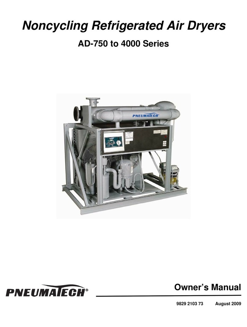
Sullair SM1100 Installation and operating instructions

Installation & Maintenance Instructions
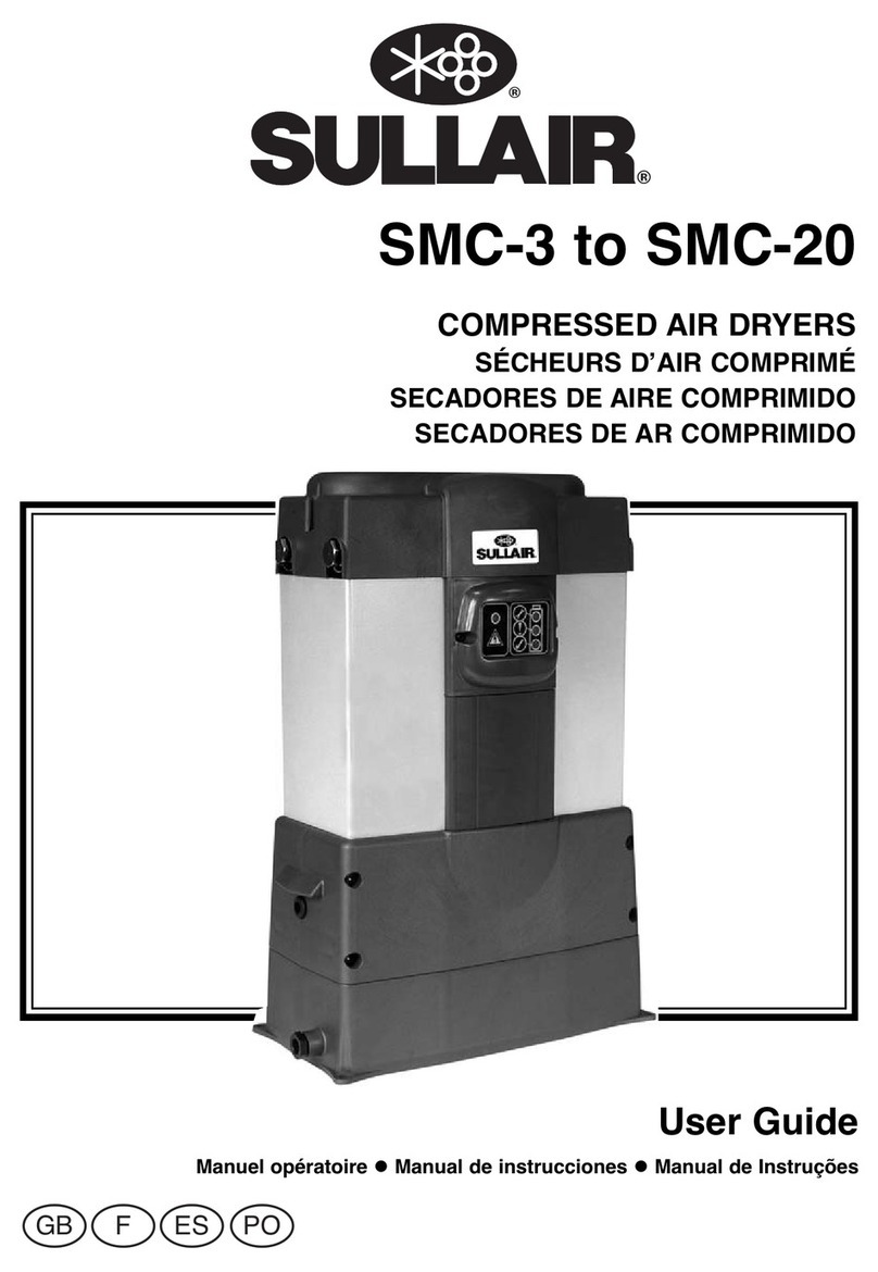
MODELS SM-1100 - SM1650 USER GUIDE
®
®
HIGH EFFICIENCY
COMPRESSED AIR DRYERS


Installation & Maintenance Instructions
MODELS SM1100N - 1650N
INDEX PAGE NO.
1 SAFETY WARNING 2
2 TECHNICAL SPECIFICATIONS A) GENERAL 3
B) DIMENSIONS 4
3 UNPACKING 5 - 6
4 INSTALLATION A) INSTALLATION CHECKLIST 7 - 8
B) POSITIONING YOUR SYSTEM 9
C) INSTALLING YOUR SYSTEM PNEUMATICALLY 10 - 11
D) INSTALLING YOUR SYSTEM ELECTRICALLY 12
i) SM MODELS 12
ii) SM REAR JUNCTION BOX 13
5 COMMISSIONING 14
6 MAINTENANCE A) MAINTENANCE PRECAUTIONS 14
B) ROUTINE MAINTENANCE 14
C) MAINTENANCE EXAMINATION 15
D) MAINTENANCE PLANS 15
E) DESICCANT SAFETY INFORMATION 15 - 16
F) KNOWN MISUSE 17 - 19
7 WARRANTY 20
8 DECLARATION OF CONFORMITY Inside Rear Cover
APPENDIX A 21 - 22
MAINTENANCE & EXAMINATION RECORD
FIGURES 1 DRYER INSTALLED AFTER ‘WET” AIR RECEIVER 9
2 TYPICAL SINGLE BANK INSTALLATION 10
3 TRANSFORMER ENCLOSURE - SM MODELS 12
INDEX
1

2
1. SAFETY WARNING!
Do not operate the dryer until the operating instructions for the particular control system and this manual have
been read and understood by all personnel concerned.
It is essential that personnel employ safe working practices and observe all related regulations and legal requirements for
safety when operating the dryer.
When handling, operating or carrying out maintenance on the dryer, personnel must employ safe engineering practices
and observe all relevant local health and safety requirements and regulations. The attention of UK users is drawn to the
Health and Safety at Work Act 1974, and the Institute of Electrical Engineers Regulations.
Most accidents which occur during the operation and maintenance of machinery are the result of failure to observe basic
safety rules or precautions. An accident can often be avoided by recognising a situation that is potentially hazardous.
Improper operation or maintenance of the dryer could be dangerous and result in an accident causing injury or death.
Sullair can not anticipate every possible circumstance which may represent a potential hazard. The WARNINGS in this
manual cover the most common potential hazards and are therefore not all-inclusive. If the user employs an operating
procedure, an item of equipment or a method of working which is not specifically recommended by Sullair he must ensure
that the dryer will not be damaged or made unsafe and that there is no risk to persons or property.
Your attention is drawn to the pre-use checklist and commissioning information found within this dryer Installation and
Maintenance Instructions
IMPORTANT
SAFETY SIGNS
Operations or procedures involving specific hazards which could cause injury or death if precautions are not heeded, are
identified by the following symbols which are displayed on the desiccant air dryer to indicate potential danger points.
CAUTION : RISK OF ELECTRIC SHOCK
WARNING : RISK OF DANGER
CAUTION : RISK OF HIGH PRESSURE
IT IS STRONGLY RECOMMENDED THAT THE OPERATING INSTRUCTIONS FOR THE PARTICULAR CONTROL
SYSTEM AND THESE INSTALLATION AND MAINTENANCE INSTRUCTIONS ARE READ THOROUGHLY BEFORE
PROCEEDING ANY FURTHER.
PLEASE NOTE: YOUR WARRANTY MAY BE INVALIDATED IF THE EQUIPMENT HAS NOT BEEN INSTALLED,
COMMISSIONED OR MAINTAINED BY Sullair OR ITS APPROVED AGENTS.

3
2. TECHNICAL SPECIFICATION
Type:
Model:
Outlet Dewpoint:
Air Quality:
(dirt/water/oil):
Maximum Operating Pressure:
Minimum Operating Pressure:
Maximum Inlet Temperature:
Minimum Inlet Temperature:
Regeneration:
Nominal pressure drop
across desiccant bed:
Standard Electrical Supply:
Controls:
Controller:
Noise Level (Average):
Media:
Material:
Construction:
Pre filtration:
After filtration:
A) GENERAL
Heatless
SM
-40°C (-40°F)
ISO 8573.1 Class 1.2.1
Class 1.1.1 optional
13.0 bar g (189 psi g)
4 bar g (58 psi g)
50°C (122°F)
5°C (41°F)
Pressure Swing Adsorption (PSA)
[Air Purge Principle]
140 m bar (2 psi)
115/230V/1ph/50Hz/60Hz
Control equipment 24V ac.
SM - electronic with integrated display
<85db (A)
Desiccant
High tensile extruded aluminium coated with Alocrom anti-corrosion
protection and paint finished with an abrasion resistant dry powder epoxy
coating.
The dryer is constructed from extruded aluminium sections connected
together by high tensile bolts i.e. desiccant filled columns are contained
between an upper and lower manifold. The configuration varies between the
heatless and heat regenerative models as shown in figures 1 & 2
Grade MPF/MPH filters
Grade MPR filter

4
B) DIMENSIONS
1895 1142.5 825 3" 765 MPR-1315 3"
(74.5) (45) (32.5) (1683)
2223 1470.5 1153 4" 895 MPR-2120 4"
(87.3) (58) (45.5) (1969)
2551 1798.5 1143 4" 1025 MPR-2120 4"
(100) (71) (45) (2255)
Dimensions in mm(“) Pipe Wt Recom. Recom. Filter
A B C Con. kg.(lbs) Inlet Filter Outlet Filter Con.
MPF-1315
MPH-1315
MPF-2120
MPH-2120
MPF-2120
MPH-2120
SM-1100
SM-1380
SM-1650

5
3. UNPACKING
12
34

6
7
56

7
4. INSTALLATION
A) INSTALLATION CHECKLIST
DO
✔Ensure that the dryer is correctly sized for the inlet pressure, taking into consideration pressure drops caused by
valves, pipes, filters etc. Allowance should be made for purge air loss. The dryer should be typically sized at 1
bar g (14 psi g) below nominal compressor output pressure.
✔Ensure that the dryer is correctly sized for inlet temperature and to meet the dewpoint specified e.g.
-40˚C (-40˚F) or -70˚C (-100˚F) .
✔A receiver MUST be fitted before the dryer to ensure optimum performance. (Establish the volume flowrate of
compressed air required and calculate variation in air demand to establish the size of air receiver required).
✔The pipe should predominantly remain at compressor discharge size. On multibank installations, ensure that
dryers are located in an end fed manifold arrangement, as shown below.
✔Ensure that the dryer is securely mounted on a suitably structured, flat and level floor or base which is free from
vibration. It should be secured to the base using bolts located through the slots in the mounting feet.
✔Ensure that there is sufficient space around the equipment for safety and maintenance, including space for lifting
tackle and loading.
✔Ensure minimum distance between dryer bank centres is 500mm (19.7”).
✔Check rating plate for correct supply voltage/frequency.
✔Electrical isolators should be provided in a safe and accessible place and rated correctly for the power required.
Miniature Circuit Breakers (MCB’s) MUST be used.
✔The installation should be properly ventilated to allow easy dissipation of generated heat.
✔Ensure that the correct quality, size and type of filtration equipment is fitted e.g. WS, MPF and MPH grades
before the dryer and AR grade after the dryer.
✔Noise MPR should be considered when choosing a site for the dryer.
✔Ensure that water removed by the dryer is allowed for. If the exhaust is to be piped away, ensure adequate pipe
sizes are used e.g. min 100mm (4").
✔Separate drainage should be fitted to each filter condensate drain and piped away. Ensure that any effluent is
disposed of properly, to conform with legal requirements e.g. O.S Oil/Water Separator.
INLET LAYOUT
Dryer Dryer Dryer
Flexible
Connection
OUTLET LAYOUT
Dryer Dryer Dryer

8
DO NOT
✘Install the dryer flat against a wall.
✘Install the dryer without adequate pre- and after-filtration.
✘Install multiple banks with 750mm (29.5”) between modules (the instrumentation shroud will not open).
✘Manifold multiple banks in a centre fed (fork) arrangement, as shown below.
Inlet

9
B) POSITIONING YOUR SYSTEM (See Figure 1)
A typical dryer installation is illustrated below, where the dryer is sized to match the output of the compressor
and installed downstream of a 'wet' air receiver. Care must be taken to ensure that the dryer cannot be
subjected to flows (even peak flows) in excess of its full rated flow capacity.
As the dryer is sized to the compressor output, the potential therefore exists for overflowing i.e. the system can
draw volumes of air in excess of the compressor output by also utilising the stored volume in the air receiver.
To prevent overflow, ensure (where applicable) a Flow Control Device (FCD) is fitted into the outlet flexible
connection. This will indicate via high differential pressure when the dryer is being overflowed.
Figure 1 - PNEUDRI INSTALLED AFTER A ‘WET‘ AIR RECEIVER
In the ideal situation Sullair would always recommend a receiver to be fitted both before and after the
desiccant air dryer.
The dryer should be securely mounted on a suitably structured, flat and level floor or base which is free from
vibration. It should be secured to the ground using bolts located through the slots in the mounting feet.
Ensure there is sufficient space around the dryer(s) and 750mm (29.5”) (minimum distance) between dryer
modules.
MPR
WS
MPF
MPH
‘Wet’ Air
Receiver
DRYER

10
C) INSTALLING YOUR SYSTEM PNEUMATICALLY (See Figure 2)
Install the dryer where the ambient air is as clean as possible and where the air temperature will never exceed
the dryers temperature limits.
PNEUMATIC CONNECTIONS
Connect the Inlet (1) and Outlet (2) compressed air lines to the valve housings marked Inlet and Outlet, ensuring
the protective dust covers fitted to the flanges on the dryer are removed prior to connection.
MANIFOLD & DRAINS
On installations with fabricated manifolds, an automatic drain valve must be fitted at the lowest point of the inlet
manifold to prevent condensate from entering the dryer.
Figure 2 - TYPICAL SINGLE BANK INSTALLATION
6
2435
1
10
9
7
8
8

11
Recommended inlet and outlet fabricated manifolds to suit each dryer are listed below.
INLET & OUTLET DISTRIBUTION MANIFOLDS
For larger installations please contact Sullair
FILTRATION
Ensure the dryer is protected with the correct pre- and after-filtration with the flow directional arrows correctly
aligned with the dryers flow path.
It is recommended that each dryer bank has its own independent filtration. Size 910 filters should be used on
banks of up to and including 6 columns; size 1315 filters should be used on banks of 8 columns & size 2120
filters should be used on banks of 10 columns
PRE-FILTRATION
This must be positioned as close to the dryer inlet as possible. Sullair grades ‘MPF’ (3) and ‘MPH’ (4) pre-filters
must be fitted upstream of the inlet to prevent contamination of the desiccant beds.
In cases of extreme contamination, a Sullair Water Separator (5) (WS grade) should be incorporated into the
system.
AFTER-FILTRATION
ASullair grade ‘MPR’ (6) filter must be fitted downstream of the dryer to prevent dust carryover.
BYPASS LINE AND VALVE
It should be noted that the use of a bypass line (7) allows wet and untreated air into the system. For continuous
duty, a standby dryer should be installed. Even with multi-bank systems, this means that only one more bank
is required, which offers the benefit of 100% standby.
SHUT-OFF VALVES (ISOLATION)
Shut-off valves (8) must be fitted to the inlet and outlet pipework of each dryer bank and are used during the
“Bring online/Take offline” procedures and during maintenance periods.
MODEL PIPE DIAMETER
SM1100 3"
SM1380/1650 4"
SM2X1100 8"
SM2X1380/1650 10"
SM3X1380/1650 12”

D) INSTALLING YOUR SYSTEM ELECTRICALLY
Installation should only be carried out by a qualified electrical engineer.
Ensure that the dryer is connected to a suitably rated AC supply with means of external fused isolation.
The dryer must only be used on alternating current (AC) at the voltage shown on the rating plate (fixed
to the instrumentation shroud) and MUST BE EARTHED.
i) SM MODELS
GENERAL
The SM range of compressed air dryers have the provision for dual voltage operation at either 110V 50/60Hz or
230V 50/60Hz. This is not an automatic process and a selector switch in the transformer enclosure must be set
to the correct position before switching on for the first time.
The dryer must be powered from an externally fused electrical supply.
The suggested electrical supply cable is 3 core, 1.5mm2(16AWG).
The dryer must be earthed/grounded.
ELECTRICAL CONNECTION (See Figure 3)
Open the control shroud (9 - Figure 2) and locate the transformer enclosure (See Figure 3 for general
appearance). Remove the four corner screws which retain the clear lid and remove the lid
Remove a blanking grommet from one of the shroud supports and feed the supply cable through and into the
transformer enclosure via the unused cable gland (1).
Connect the cables to the terminals (2) as shown in Figure 3 and ensure the voltage selector switch (3) displays
the correct voltage. Tighten the cable gland (1) and replace the box lid.
OPTIONAL CONNECTION
For remote fault indication a volt free relay is fitted. To access this feature feed the cable through the shroud
support as above and into the transformer enclosure via the unused cable gland (4) after removing the blanking
plug. The connections to the relay are shown in Figure 3. In normal operation, the relay is permanently
energised and will de-energise in the event of a power failure or fault condition. The relay is designed to provide
a fault signal and is rated at 250VAC, 1A maximum.
12
Figure 3 - TRANSFORMER ENCLOSURE - SM MODELS
CUSTOMERS MAINS
INPUT CABLE
CUSTOMERS
FAULT RELAY
CONNECTIONS
11 COMMON
12 FAULT
14 OK
EARTH / GROUND

iv) SM REAR JUNCTION BOX
1. Isolate the dryer electrically.
2. Make connections as shown below:-
If a DPE or drain connection is not used, leave the gland blanked off.
3. Connect at DPE’s in accordance with DPE Installation Manual supplied.
4. Connect at Drain Alarm connection in accordance with SCD supplied.
5. Re-apply power to the dryer.
13
To temperature
sensor
From controller
CONNECTION FROM BOTTOM OF
TERMINALS
1. Ready Made
2. Ready Made
3. Ready Made
4. Ready Made
5. Ready Made
6. Ready Made
7. WS Drain supply
8. MPF Drain supply
9. MPH Drain supply
10. Ready Made
11. Unused
12. Unused
13. Ready Made
14 Ready Made
CONNECTION FROM TOP OF
TERMINALS
1. Ready Made
2. Ready Made
3. DPE 1 Feedback (MPF)
4. DPE 2 Feedback (MPH)
5. DPE 3 Feedback (MPR)
6. Unused
7. DPE 1 supply (MPF)
8. DPE 2 supply (MPH)
9. DPE 3 supply (MPR)
10. WS Drain Feedback
11. MPF Drain Feedback
12. MPH Drain Feedback
13. ABV 24VAC
14 ABV Neutral

14
5. COMMISSIONING
6. MAINTENANCE
IMPORTANT INFORMATION CONCERNING THE WARRANTY
Each dryer must undergo a detailed start-up procedure.
This must be carried out by Sullair or an approved engineer from a Sullair authorised distributor.
During start-up, ensure that the dryer is installed and continuously maintained and operated in the manner
specified in this manual.
A) MAINTENANCE PRECAUTIONS
Maintain and keep a written record of all maintenance and repair work carried out on the dryer and its’ auxiliary
equipment (see Appendix A).
The frequency and nature of the work required over a period can reveal adverse operating conditions which
should be corrected.
Ensure that all instructions concerning operating and maintenance are strictly followed, and that the complete
unit, with all accessories and safety devices is kept in good working order.
Maintenance, overhaul and repair work must only be carried out by either Sullair or a Sullair authorised
distributor.
Before dismantling any part of the dryer ensure that all heavy movable parts are secured.
B) ROUTINE MAINTENANCE
At regular intervals check the following:
(Ensure that all necessary safety precautions are undertaken when working with pressurised components).
1. Dryer and system for leaks.
2. Open kaddis drains on lower manifold, inlet and exhaust valve assemblies, to remove any entrained moisture.
3. Differential pressure indicators and kaddis drains on filters.
4. Exhaust silencer (should be changed when differential pressure exceeds 350 m bar (5 psi) or annually,
whichever is earliest).
5. Inlet and outlet filtration (should be changed when differential pressure exceeds 350 m bar (5 psi) or annually,
whichever is earliest).
6. Use only GENUINE Sullair spare parts.

C) MAINTENANCE EXAMINATION
The user of the equipment may be subject to the requirements of the PRESSURE SYSTEMS REGULATIONS
(1989). These regulations require regular maintenance, examination and the keeping of records of all
examination, tests and any repairs undertaken.
The Sullair SM range of desiccant compressed air dryers are regarded under Regulation 2, not as a pressure
vessel, but as a pressure containing component, such as equipment that is not fabricated or welded (e.g. filters,
pressure regulators, refrigerant dryers).
The period of inspection under the regulations is to be decided by the owner of the equipment, but Sullair would
recommend that the dryers aluminium componentry is internally inspected for corrosion within a six year period,
or whenever the desiccant material is changed.
D) MAINTENANCE PLANS
Sullair offers a comprehensive range of service plans tailored to suit your requirements to ensure the optimum
operating performance of your dryer is maintained at all times.
For further details, please contact the Sullair Service Manager, or a Sullair authorised distributor.
E) DESICCANT SAFETY INFORMATION
Instructions for use of ‘SNOWSTORM’ filler
Sullair ‘snowstorm’ fillers must always be used when recharging compressed air dryers with DRYFIL®
desiccant material.
THE “SNOWSTORM” FILLER
To ensure optimum performance from the dryer, it is essential to
‘
snowstorm’ fill with DRYFIL®desiccant material,
recharging using a genuine Sullair “snowstorm” filler.
The filler controls the flow of desiccant material to achieve maximum
packing density, and avoids channelling and fluidisation, preventing
attrition and rapid deterioration of the desiccant bed.
USE OF THE “SNOWSTORM” FILLER
After removing the expended desiccant, place the filler on top of the
empty dryer column, using the pins in the base for positive location
over the centre of the column chamber.
Pour desiccant into the filler ensuring continuous filling is maintained
where possible. As the chamber becomes full, it is possible to monitor
through the perspex base the quantity of desiccant required to
complete the filling process without causing spillage.
IMPORTANT NOTE:
To ensure reliability, always refill the dryer with DRYFIL®desiccant
material recharged using a genuine Sullair ‘snowstorm’ filler.
DRYFIL®DESICCANT SAFETY DATA
Sullair DRYFIL®desiccant is a high performance Zeolite Molecular
Sieve which is “NON-HAZARDOUS” for transportation. It is formed into spherical particles using clay binders,
buff coloured, non-volatile and non-flammable.
15

16
DRYFIL®DESICCANT SAFETY DATA
Sullair DRYFIL®desiccant is a high performance Activated Alumina blend which is “NON-HAZARDOUS” for
transportation. It is formed into spherical particles using clay binders, buff coloured, non-volatile and non-
flammable.
HANDLING PRECAUTIONS
The product may contain some dust, if so an orinasal dust respirator should be worn when handling the product.
By providing adequate ventilation the dust levels in the working atmosphere should be maintained below
10mg/m3, the recommended maximum level for nuisance dusts.
The product is a powerful desiccant and will dry out the atmosphere, eyes, nose and mouth.
Eyes and skin coming into contact with dust or product should be washed with copious amounts of clean water.
If symptoms develop consult a doctor.
Any spillage should be swept away immediately because the spheres roll freely and it is very easy to slip if
walked on.
TRANSPORTATION AND TARIFFS
DRYFIL®is classified as “NON-HAZARDOUS” for transportation.
STORAGE
The product is stable indefinitely at ambient temperature. It will, however, lose its desiccant and adsorption
properties when heated to 900˚C (1652˚F).
This product evolves heat on contact with moisture. Ideally, it should be stored in a clean dry warehouse, in the
original package, on pallets.
It should not be stored with materials subject to catalytic decomposition.
FIRE AND EXPLOSION HAZARD
The product is non-flammable. Any fire should be fought by means appropriate to the material causing the fire.
Contact with water will cause the evolution of heat and may thus generate pressure in a confined space.
HANDLING AND DISPOSAL OF SPENT MATERIAL
This information is dependent upon the application. Great care should be exercised with spent material. As a
powerful adsorbent, the product may retain hazardous or flammable components from the process fluid. The
process vessels should be purged of contaminants before discharge, normally after regeneration. To remove
residual vapours the spent product should be thoroughly drenched with water during or after discharge.
CAUTION! HEAT WILL BE GENERATED!
It is also possible that the product may contain decomposition, polymerisation or trace contaminants from the
process fluid and should be treated accordingly. Dust may have been created in service.
The product should be disposed of into a licensed land fill site.
This reply is based on information which was available at this moment in time. To the best of our knowledge we
believe this information to be correct at the time of printing.

17
F) KNOWN MISUSE
(Please ensure that the following do not occur in your installation).
INLET FILTERS
* Installation of filters remote from dryer allowing further condensation to occur between filters and the dryer.
* Blow down valve upstream of filters causing back flow/possible collapse of filter element.
* Installing MPH/MPF filters in wrong flow direction.
* Opening inlet valve too quickly, causing initial high DP across filter element.
* DP gauge fitted wrong way round giving false DP indication.
* Combining drain pipes from WS/MPF/MPH.
INLET MANIFOLD
* Pipe diameter too small, causing preferential flow on multi-bank installations.
* No automatic drains fitted to pipework.
* Unsupported pipework causing strain on gasket joints.
* Not enough clearance for removing filter bowls.
* Pipework from manifold to dryer taken from the bottom of the manifold instead of the top or centre allowing bulk
water to drain into dryer inlet.
LOWER MANIFOLD
* Pipe kinks to control valves causing poor/non-response - use of too short a pipe.
* Insufficient room to remove inlet valve assembly.
* Insufficient room to remove exhaust valve assembly.
INLET
MANIFOLD INLET
MANIFOLD
TO DRYER TO DRYER
either way is ok

18
COLUMNS
* Omission or use of incorrect snowstorm filling devices.
* Excessive exposure of desiccant to atmosphere during filling.
* Hand filling or ‘topping up’ without correct filler.
* Leaving desiccant media in bolt holes when torquing down top manifold bolts.
* Failure to remove all desiccant from column during desiccant change.
TOP MANIFOLD/OUTLET VALVE
* Incorrect torquing of column bolts - sequence tightening must be employed.
* Use of sonic nozzles for flow measurement.
* Cleaning of column bolts before torquing.
* Faulty torque setting.
* Use of incorrect wire stripping tools.
CONTROL BOX
* Excessive voltage drop on incoming supply.
* Purge setting by amps, non-use of flow meters.
* Incorrect fusing used (external).
* Incorrect supply wire (incoming).
* No earth wire between earth terminal and armour cable clamp on shroud.
ADDITIONAL ITEMS
* Use of non-recommended desiccant or non-genuine Sullair spare parts from alternative suppliers.
* Servicing undertaken by untrained personnel.
* Inability to maintain inlet pressure and temperature at levels stated for sizing.
* Not to use dryer/dryers if piped directly after a portable compressor.
FASCIA
* Depression of press buttons with sharp objects (e.g. keys, screwdrivers etc).
* Subjected to bulk water spray.
* Operation of the dryer with control fascia open.
This manual suits for next models
7
Table of contents
Other Sullair Dehumidifier manuals

Sullair
Sullair SD Series User manual
Sullair
Sullair SD-820 Series User manual
Sullair
Sullair SRL Series User manual
Sullair
Sullair SM-160N Installation and operating instructions
Sullair
Sullair SRHT-15 User manual
Sullair
Sullair DBP Series Troubleshooting guide
Sullair
Sullair SD Series User manual
Sullair
Sullair DHL-80 Troubleshooting guide
Sullair
Sullair SRC User manual

Sullair
Sullair SAR024 User manual

