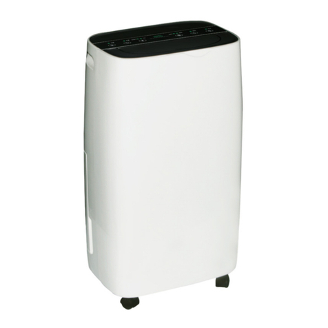
Sullair SMC-3 User manual

User Guide
Manuel opératoire Manual de instrucciones Manual de Instruções
SMC-3 to SMC-20
COMPRESSED AIR DRYERS
SÉCHEURS D’AIR COMPRIMÉ
SECADORES DE AIRE COMPRIMIDO
SECADORES DE AR COMPRIMIDO
GB F ES PO
®
®

English 1
Français 15
Español 29
Português 43

1
WARNING!
Do not operate the dryer until the instructions in this manual have been read and understood by
all personnel concerned.
When handling, installing or operating, personnel must employ safe engineering practices and observe all
related regulations, health and safety procedures, and legal requirements for safety.
Most accidents that occur during the operation and maintenance of machinery are the result of failure to
observe basic safety rules and procedures. Accidents can be avoided by recognising that any machinery
is potentially hazardous.
Sullair can not anticipate every possible circumstance which may represent a potential hazard.
The WARNINGS in this manual cover the most known potential hazards, but by definition cannot be all
inclusive. If the dryer user employs an operating procedure, item of equipment or a method of working
which is not specifically recommended by Sullair the user must ensure that the dryer will not be damaged
or made a potential hazard to persons or property.
IMPORTANT
Caution: Power
Risk of Electric Shock
Attention
PLEASE NOTE THAT YOUR WARRANTY MAY BE INVALIDATED IF THE EQUIPMENT HAS NOT
BEEN INSTALLED, COMMISSIONED AND MAINTAINED BY Sullair OR A Sullair APPROVED
AGENT.

2
INDEX
1.0 Introduction 3
2.0 Installation 4
3.0 Start-up and Operation 10
4.0 Maintenance 12
5.0 Spare Parts 13
6.0 Troubleshooting 14

3
INTRODUCTION
The SMC range of compressed air dryers are designed to remove moisture from
compressed air by utilising state of the art technology to obtain dewpoints of -40°F
PDP and by appropriate de-rating -100°F PDP.
SMC dryers have been designed to require minimal maintenance and can be installed
virtually anywhere.
The SMC dryer consists of upper and lower head assemblies joined together with an
aluminium extrusion containing twin internal chambers. The upper head assembly
contains inlet and outlet manifolds, pre-filter and autodrain. The lower head assembly
contains two exhaust valves and a passive shuttle ball valve. Contained in each
internal chamber is a combination desiccant / after-filter cartridge. During operation
one chamber is on-line (drying) while the other is regenerating, using the Pressure
Swing Adsorption (PSA) process.
Pressure Swing Adsorption (PSA)
A small percentage of dried air is taken from the dryer outlet flow and is used to
regenerate the saturated chamber by expanding the dried air from line pressure to
atmospheric pressure. During this process, the moisture is physically removed from
the regenerating chamber and vented to atmosphere through the exhaust.

4
2.0 INSTALLATION (refer to figure 1)
2.1 ESSENTIAL INFORMATION
Care must be taken to ensure that the dryer is not subject to flows (even peaks) in
excess of the dryers rated capacity, e.g. dryers downstream of an air receiver have
increased potential to be overflowed.
The dryer can be installed free standing, secured to the floor via the fastening points
provided in the base or secured to a wall using optional brackets.
The control enclosure (A) must be at the bottom and the dryer must be installed
vertical and level.
Two inlet and two outlet connections are available at the top of the dryer to enable
connection from either left or right. Unused connections (B) and (C) must be sealed
with the threaded plugs provided. Suitable rated pipe and connections must be used
for the installation. All pipework must be secure and safely positioned.
The purge flow is factory set for 87 psi g minimum operating pressure. Should the
minimum pressure requirement be different, the purge flow must be reset by a Sullair
engineer or a Sullair approved agent.
Ensure the dryer is electrically connected to a supply suitable for the unit. See wiring
diagram printed in 2.3 Electrical Details.
1. Filtration
A 0.01 micron pre-filter is contained within the upper head assembly. 1 micron after-
filters are integral within desiccant cartridges screwed into inserts in the upper head
assembly. Filters must be maintained by Sullair or a Sullair approved agent.
2. By-pass Line (D)
A by-pass line, 3/8" NPT (D) ensures complete safety during maintenance and
enables a continuous supply of compressed air to be maintained if required. It should
be remembered that air bypassing the dryer is dirty untreated air.
3. Valves (E, F, G)
Isolation valves, 3/8" NPT are recommended on the inlet (E), outlet (F) and bypass (G)
lines at the positions indicated in Figure 1.

5
2.2 TECHNICAL SPECIFICATION
Operating Specification
Parameter Minimum Maximum Nominal
Inlet Pressure 58 psi g (4.0 bar g) 175 psi g (12.0 bar g) 102 psi g (7.0 bar g)
Parameter Minimum Maximum Nom inal
Inlet Temperature 35˚F (1.5˚C) 122˚F (50˚C) 95˚F (35˚C)
Electrical Specification
Dryer Model Voltage Supply Supply Need Electrical Approval
60 Hz 24V / 115 / 230 V 1 phase CE
50 Hz 24V / 115 / 230 V 1 phase CSA/UL
General Specification
Inlet Flowrate
SMC-3 3 cfm 5.1 m3/hr
SMC-5 5 cfm 8.5 m3/hr
SMC-8 8 cfm 13.6 m3/hr
SMC-10 10 cfm 17.0 m3/hr
SMC-13 13 cfm 22.1 m3/hr
SMC-15 15 cfm 25.5 m3/hr
SMC-20 20 cfm 34.0 m3/hr
Outlet Dewpoint -40 ˚F (-40˚C) Optional – -100˚F (70˚C)
Environmental Protection IP65 (NEMA4)
Noise Level <70 dB(A)
Dryer Weights
SMC-3 24.3 lbs 11 Kgs
SMC-5 28.7 lbs 13 Kgs
SMC-8 35.3 lbs 16 Kgs
SMC-10 39.7 lbs 18 Kgs
SMC-13 44.1 lbs 20 Kgs
SMC-15 50.7 lbs 23 Kgs
SMC-20 61.7 lbs 28 Kgs
Note: All flow rates referenced at 68˚F (20˚C) , 102 psi g (7 bar g)

6
2.3 ELECTRICAL DETAILS
Only competent qualified electricians must work on dryer circuitry.
Check the rating plate for power supply requirements.
Correct isolator switches must be provided at a safe and accessible point near to the
dryer.
The dryer must be provided with a live, neutral and earth.
Connect power to the dryer (via the conduit entry aperature *) at the fused terminal
block mounted on the small base plate located under the enclosure. Four screws
retain the base plate.
*For CE/BSP dryers, the conduit entry aperature is replaced by a mains cable gland
Brown
Blue
Live
Earth
Neutral
T500mA / T1A / T2A
230V, 50Hz - T500mA
115V, 60Hz - T1A
24V, 50 / 60Hz - T2A
ground

7
KEY
(A) Control Box (E) Inlet Valve
(B) Optional Inlet (F) Outlet Valve
(C) Optional Outlet (G) By-pass Valve
(D) By-pass Line (H) Display Unit
2.4 INSTALLATION PROPOSAL
Figure 1
3/8”NPT
!
✓
H
Orange Red
Orange
Green

8
Position 1
Dryers running below
102 psig (7 Bar g)
Position 2
Dryers running above
102 psig (7 Bar g)
2.5 RUNNING THE DRYER WITH A MINIMUM PRESSURE BELOW 102 PSIG
If the dryer is to be run with a minimum pressure of 102psig (7 Bar g) an alteration to
the timer board is required.
To carry out the alteration,ensure the electrical supply is isolated, lie the dryer on its
back, to gain access to the control base. Remove the large plate to gain access to the
timer board. Move electric jumper from Position 1 to Position 2, as shown.

9
3.0 START-UP AND OPERATION
3.1 INTIAL STARTUP
Ensure a suitable supply of compressed air between 58 psi g and 175 psi g pressure
is available and check that the dryer cannot be overflowed. Inlet temperature must be
between 34°F to 122°F at all times.
IMPORTANT NOTE
Ensure all valves are opened and closed gradually.
Proceed as follows: (Refer to figure 1)
3.2 WITHOUT THE BY-PASS LINE (D)
Close inlet (E) and outlet (F) valves.
Introduce air to the dryer by gradually turning the inlet valve (E) until fully open.
Allow dryer to fully pressurise, then gradually open the outlet valve (F).
Switch on the electrical isolator, the yellow ‘power on’ LED and the green ‘correct
operation’ LED will illuminate and the dryer will commence cycling. The dryer is now
on stream.
3.3 USING THE BY-PASS LINE (D)
With the inlet (E) and outlet (F) valves closed and the by-pass (G) valve open,
introduce air to the dryer by gradually turning inlet valve (E) until fully open.
Allow the dryer to fully pressurise, then open the outlet valve (F) while simultaneously
closing the by-pass valve (G).
Switch on the electrical isolator, the yellow ‘power on’ LED and the green ‘correct
operation’ LED will illuminate and the dryer will commence cycling. The dryer is now
on stream.
3.4 NORMAL OPERATION
Following the start-up procedure the operation of the dryer is fully automatic and
requires no further attention until shut down.
The yellow ‘power on’ LED and the green ‘correct operation’ LED should be illuminated
continuously.
!
✓
*
Power On
Correct Operation
*

10
The dryer contains two desiccant chambers, while one chamber is drying the
compressed air (adsorption), the other chamber is simultaneously undergoing
regeneration (desorption). At a predetermined time both exhaust valves close and
repressurisation begins. Every three minutes the chambers are reversed in function,
this is the changeover point. Changeover is characterised by an immediate venting of
compressed air from the chamber entering regeneration.
The dryer can be shut down at any point in its cycle and when restarted will enter an
automatic repressurisation stage. After repressurisation the cycle will commence at
the point at which it stopped.
NB
If power is switched on, the dryer will enter an automatic repressurisation stage at the
point at which it stopped.
3.5 SHUT-DOWN PROCEDURE
To Depressurize the Dryer
Prior to isolating the electrical supply close the outlet valve (F) while simultaneously
opening the by-pass valve (G) if fitted. Close the inlet valve (E). The dryer will now be
isolated from mains pressure. Cycle the dryer for a minimum of 3 minutes to ensure
the dryer vents and is completely depressurized. When the dryer is completely
depressurized, isolate the electrical supply.
NB
The by-pass valve (G) should only be opened if the dryer is undergoing maintenance.

11
4.0 MAINTENANCE
Daily
• Ensure the yellow ‘power on’ LED and the green ‘correct operation’ LED are
illuminated.
Weekly
• Check dryer seals, fittings and pipe work for air leaks.
• Ensure correct operation of inlet filtration condensate drainage.
The Combination desiccant / after-filter cartridges have a finite life dependent upon
operating conditions.
Cartridge status is indicated
Cartridges require changing and audible alarm will sound every 6 seconds.
NOTE: Temporary resetting of the alarm to prevent nuisance noise is possible after
alarm has sounded for the first time. This is done by depressing once the reset button
located inside the control enclosure, accessed by removing the black insert on the
side. The alarm will be muted for a 24 hour interval until the dryer has been serviced
and the reset sequence completed.
Servicing of the dryer must only be carried out by Sullair personnel or trained Sullair
service agents.
!
✓
!
✓
*
*
Power On
Power On
Cartridge Wear
Service Required
*
*

12
5.0 SPARE PARTS LIST
Genuine Sullair Service kits must only be used when servicing the dryer.
Dryer Model Spares Kit Part Numbers
SMC-3 02250155-152
SMC-5 02250155-153
SMC-8 02250155-154
SMC-10 02250155-155
SMC-13 02250155-156
SMC-15 02250155-157
SMC-20 02250155-158
X 2

13
6.0 TROUBLESHOOTING
Reference to Known Misuse
Filters
• Opening inlet valve too quickly, causing initial high differential pressure across
filter element.
Inlet / outlet head
• Pipe diameter too small
• Pipework unsupported
• Inlet pipework taken from low point of manifold range allowing bulk water
intrusion into the dryer.
Electric control box
• Incorrect wiring configuration by user or incorrect supply voltage.
• No fuse fitted or fuse blown.
Additional items
• Use of non-recommended components.
• Untrained, unauthorised maintenance / installation personnel used.
• Subsequent increase in air consumption without relation to dryer flow capacity.
• Purging of pneumatic system and dryer with cleaning agents that have the
potential to damage desiccant material.
• Covers removed or loose during operation.
• Cartridges and filter / autodrain not changed when red LED is illuminated.
• LED failure.
Problem Indication Probable Cause Remedy
Poor Dewpoint N/A Entrained Water Check pre-filtration and pre-filtration drains
Excessive air flow demand Check actual flow against rated flow of dryer
Check for recent additions to air system
Inlet pressure too low Check against technical specification
Excessive inlet air Check against technical specification
temperature
Insufficient purge air flow Factory set for 87 psi g system pressure
Exhaust silencers blocked Change by Sullair trained personnel
Contaminated desiccant Eliminate source of contamination. Desiccant
change by Sullair trained personnel
Cartridges not fitted Check and fit cartridges
Electrical Fault Power LED ‘OFF’ Hardware fault Contact Sullair customer service
Failure to purge No depressurisation Purge valve blocked or shut domnick hunter trained personnel to adjust
and poor dewpoint Exhaust silencer blocked Change by Sullair trained personnel
Outlet air flow Downstream No air supply to the Check compressor air supply to dryer
stops pressure drops dryer Check all pipework and fittings for leaks
Constant Erratic air flow from Damaged valve Change by Sullair trained personnel
depressurisation exhaust

14
ATTENTION !
Ne pas faire fonctionner le sécheur avant que les instructions de ce manuel aient été lues et
comprises par tous les personnels concernés.
Lors de la manipulation, de l’installation ou de l’exploitation, le personnel doit utiliser des pratiques
d’ingénierie sécurisées et observer l’ensemble des règlements liés, procédures d’hygiène et sécurité et
exigences juridiques de sécurité.
La plupart des accidents qui surviennent lors de l’exploitation et de l’entretien des machines résultent de
manquements aux procédures et règles de base de la sécurité. Les accidents peuvent être évités en
reconnaissant que n’importe quelle machine est potentiellement dangereuse.
Sullair ne peut prévoir toutes les circonstances possibles qui peuvent représenter un risque potentiel.
Les AVERTISSEMENTS de ce manuel couvrent la plupart des risques potentiels connus mais, par
définition, ne peuvent être exhaustifs. Si l’utilisateur du sécheur emploie un mode opératoire, un
équipement ou une méthode de travail qui n’est pas spécifiquement recommandée par Sullair,
l’utilisateur doit s’assurer que le sécheur ne sera pas endommagé ou ne constituera pas un risque
potentiel pour les personnes ou les biens.
IMPORTANT
Prudence : Équipement sous tension
Risque de choc électrique
Attention
VEUILLEZ NOTER QUE VOTRE GARANTIE PEUT ÊTRE INVALIDÉE SI L’ÉQUIPEMENT N’A PAS
ÉTÉ INSTALLÉ, MIS EN SERVICE ET ENTRETENU PAR Sullair OU UN AGENT AGRÉÉ PAR Sullair.

15
TABLE DES MATIÈRES
1.0 Introduction 17
2.0 Installation 18
3.0 Démarrage et exploitation 24
4.0 Entretien 26
5.0 Pièces détachées 27
6.0 Dépannage 28

16
INTRODUCTION
La gamme SMC de sécheurs d’air comprimé est conçue pour éliminer l'humidité de
l'air comprimé en utilisant une technologie de pointe pour obtenir des points de rosée
sous pression de -40 °F et, par un déclassement approprié, de -100 °F.
Ces sécheurs SMC ont été conçus pour demander un entretien minimal et peuvent
être installés virtuellement n’importe où.
Le sécheur SMC se compose d’ensembles de têtes haut et bas assemblés par un
profilé extrudé d’aluminium contenant des chambres internes jumelles. L’ensemble de
têtes haut contient des collecteurs d’entrée et de sortie, un pré-filtre et une purge
automatique. L’ensemble de têtes bas contient deux soupapes d’échappement et un
sélecteur de circuit passif à tournant sphérique. Chaque chambre interne contient une
cartouche combinée déshydratant / post-filtre. En exploitation, une chambre est en
ligne (en séchage) tandis que l'autre est en régénération, par le processus
d'adsorption modulée en pression (AMP).
Adsorption modulée en pression (AMP)
Un faible pourcentage d’air séché est extrait du courant de sortie du sécheur et sert à
régénérer la chambre saturée en détendant l’air séché de la pression de canalisation
à la pression atmosphérique. Lors de ce processus, l’humidité est éliminée
physiquement de la chambre en régénération et évacuée dans l’atmosphère via
l’échappement.

17
2.0 INSTALLATION (se reporter à la figure 1)
2.1 Informations essentielles
Il faut faire attention de s’assurer que le sécheur n’est pas soumis à des débits (même
en crête) dépassant sa capacité nominale, par exemple que les sécheurs en aval d’un
collecteur d’air comprimé présentent un risque accru d’être débordés.
Le sécheur peut être posé au sol, fixé au sol via les points de fixation de sa base ou
fixé au mur par des équerres en option.
Le boîtier de commande (A) doit se trouver au fond et le sécheur doit être installé
vertical et plan.
Deux raccords d’entrée et deux raccords de sortie sont disponibles en haut du
sécheur pour permettre le raccord à gauche ou à droite. Les raccords non utilisés (B)
et (C) doivent être scellés par les bouchons filetés fournis. Des tuyaux et raccords
convenablement évalués doivent être utilisés pour l’installation. Toute la tuyauterie
doit être sûre et positionnée de façon sécurisée.
Le débit de purge est réglé en usine à 7 psi eff de pression de service minimale. Si la
pression minimale requise s’avérait différente, le débit de purge doit être réinitialisé
par un ingénieur de Sullair ou un agent agrée par Sullair.
S’assurer que le sécheur est raccordé électriquement à une alimentation qui convient
pour l’unité. Voir le schéma de câblage imprimé en 2.3 Détails électriques
1. Filtration
Un pré-filtre de 0,01 micron est contenu dans l’ensemble de têtes haut. Des post-
filtres de 1 micron sont intégrés dans les cartouches déshydratantes vissées dans les
pièces rapportées de l’ensemble de têtes haut. Les filtres doivent être entretenus par
Sullair ou un agent agréé par Sullair.
2. Conduite de dérivation (D)
Une conduite de dérivation, 3/8" NPT (D) garantit une complète sécurité lors de
l’entretien et permet de maintenir une fourniture continue d’air comprimé si
nécessaire. Il faut se souvenir que l’air qui contourne le sécheur est un air sale et non
traité.
3. Vannes (E, F, G)
Des vannes d’isolement, 3/8" NPT sont recommandées sur les conduites d’admission
(E), de refoulement (F) et de dérivation (G) aux positions indiquées à la figure 1.

18
2.2 CARACTÉRISTIQUES TECHNIQUES
Caractéristiques de fonctionnement
Paramètre Minimum Maximum Nominal
Pression d’entrée 4,0 bar eff (58 psi eff) 12,0 bar eff (175 psi eff) 7,0 bar eff (102 psi eff)
Paramètre Minimum Maximum Nominal
Température d’entrée 1,5 °C (35 °F) 50 °C (122 °F) 35 °C (95 °F)
Spécifications électriques
Modèle Alimentation Alimentation Homologation
de sécheur en tension nécessaire électrique
50 Hz 24V / 115 / 230 V Monophasé CE
60 Hz 24V / 115 / 230 V Monophasé CSA/UL
Spécifications générales
Débit d’entrée
SMC-3 3 cfm 5.1 m3/hr
SMC-5 5 cfm 8.5 m3/hr
SMC-8 8 cfm 13.6 m3/hr
SMC-10 10 cfm 17.0 m3/hr
SMC-13 13cfm 22.1 m3/hr
SMC-15 15 cfm 25.5 m3/hr
SMC-20 20 cfm 34.0 m3/hr
Point de rosée en sortie -40 °C (-40 °F), en option -70 °C (-100 °F)
Protection de l’environnement IP65 (NEMA4)
Niveau de bruit <70 dB(A)
Poids des sécheurs
SMC-3 11 Kgs 24.3 lbs
SMC-5 13 Kgs 28.7 lbs
SMC-8 16 Kgs 35.3 lbs
SMC-10 18 Kgs 39.7 lbs
SMC-13 20 Kgs 44.1 lbs
SMC-15 23 Kgs 50.7 lbs
SMC-20 28 Kgs 61.7 lbs
Remarque : Tous les débits sont référencés pour 20 °C (68 °F), 7 bar eff (102 psi eff)
This manual suits for next models
6
Table of contents
Languages:
Other Sullair Dehumidifier manuals
Sullair
Sullair SRHT-15 User manual

Sullair
Sullair SM1100 Installation and operating instructions

Sullair
Sullair SR 10 AC User manual

Sullair
Sullair SAR024 User manual
Sullair
Sullair SRL Series User manual
Sullair
Sullair DHL-80 Troubleshooting guide
Sullair
Sullair RC Series Troubleshooting guide
Sullair
Sullair SRC User manual
Sullair
Sullair SD Series User manual

Sullair
Sullair SD Series User manual

