Sulzer Mixpac T2 Series User manual

DE1
640078 ver.01
Instruction Manual
Sulzer Mixpac™ Pneumatic Dispenser
EN Original instructions
DE Originalbetriebsanleitung
FR Notice originale
ES Manual original
IT Istruzioni originali
DA Original brugsanvisning
Operating Instruction Manual
Pneumatic Dispensers
for 1- and 2-component materials,
packed in cartridges and sausages
Some illustrations may deviate from your dispenser, as these instructions cover all pneumatic
dispensers
The operating instruction is available for download on the website www.sulzerchemtech.com
Item number 640078
640078 ver.1
Betjeningsvejledning – Trykluft dispencere
Operating instructions – Pneumatic Dispencers
Bedienungsanleitung – xxxxxx
Istrozioni d’ uso – xxxxxx
Instrucciones para el menejo – xxxxxx
Notice d’ utilisation – xxxxxx
DK
GB
DE
IT
ES
FR

2
EN English ................................................. 11
DE Deutsch ............................................... 21
FR Français ............................................... 31
ES Español ............................................... 41
IT Italiano ................................................. 51
DA Dansk ...................................................61

3
640078 ver.01
A.
B. C.
D. E.
F. G.
H. I.
J. K.

4
A.
B.
C.

5
640078 ver.01
D.
E.
F.

6
G.
H.
I.

7
640078 ver.01
G.
H.
I.
J.
K.

8
3.4
4.1
5.1.2

9
640078 ver.01
5.1.3
5.1.4
5.1.5

10
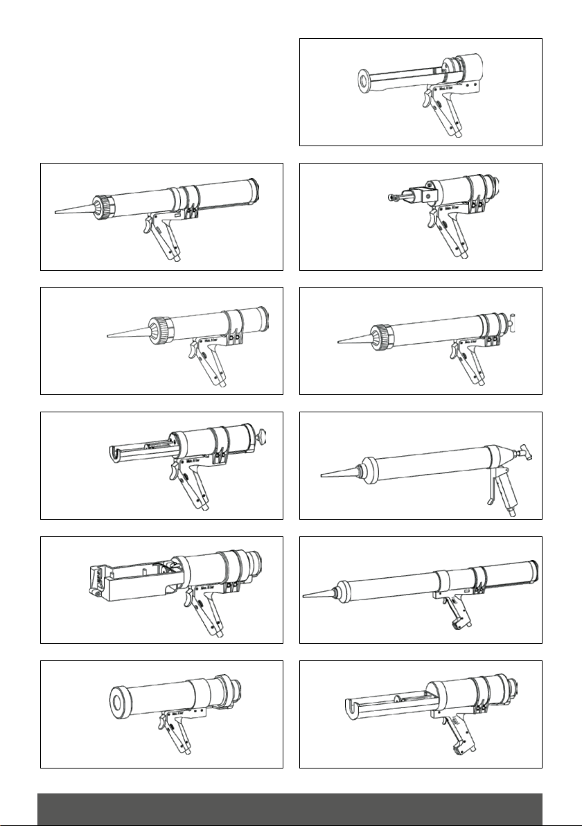
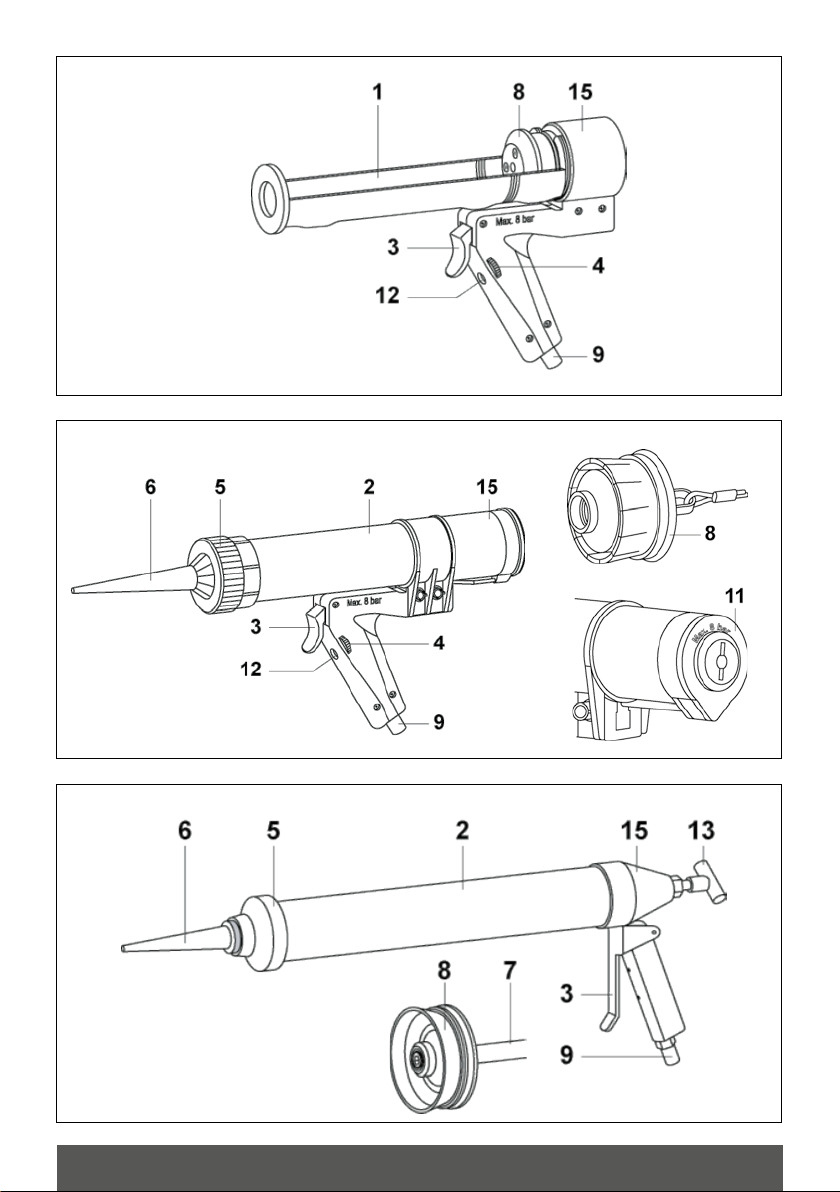
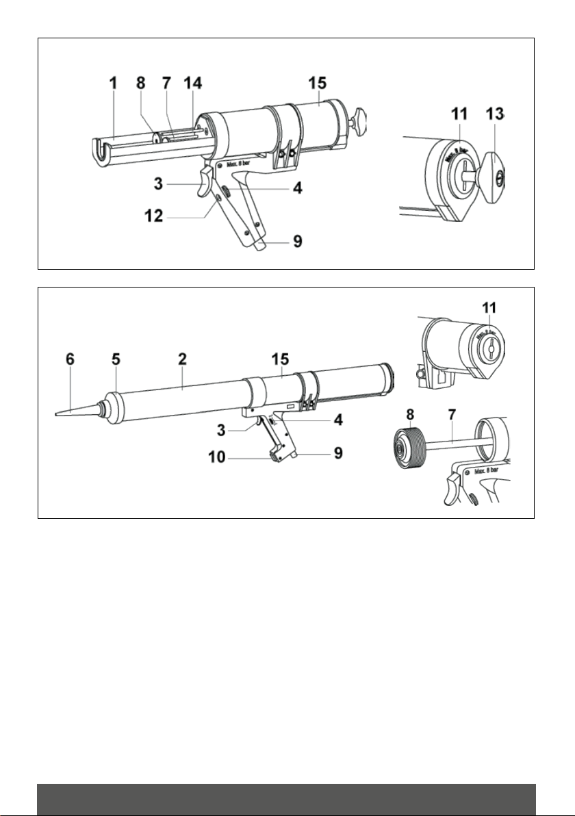
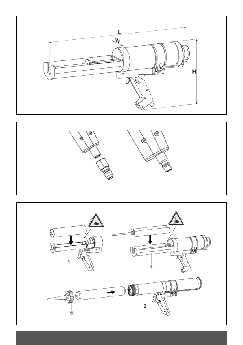
EN Some illustrations may deviate from your dispenser, as these instructions cover all
pneumatic dispensers The operating instruction is available for download on the websi-
te www.sulzerchemtech.com
Always keep this instruction manual easily accessible to users. Subject to change as a result of technical modifications.
DE Einige Abbildungen können mit Ihrem Austraggerät nicht übereinstimmen, weil diese
Betriebsanleitung alle pneumatischen Austraggeräte betrifft. Die Betriebsanleitung ist
auf der Website zum Download verfügbar www.sulzerchemtech.com
Die Betriebsanleitung muss für alle Benutzer leicht zugänglich sein. Die Betriebsanleitung kann infolge technischer Mo-
difikationen geändert werden.
FR Certaines illustrations peuvent différer de votre distributeur, car ces instructions s’appli-
quent à tous les distributeurs pneumatiques. Ce mode d’emploi est téléchargeable sur
le site www.sulzerchemtech.com
Gardez toujours ce mode d’emploi à la portée des opérateurs. Il peut être sujet à changement suite à des modifications
techniques.
ES Algunas ilustraciones pueden desviarse de su dispensador, ya que estas instrucciones
se refieren a todos los dispensadores neumáticos El manual de instrucciones está
disponible para su descarga en el sitio web www.sulzerchemtech.com
Mantenga siempre este manual de instrucciones de fácil acceso para los usuarios. Puede estar sujeto a cambios, como
resultado de modificaciones técnicas.
IT Alcune illustrazioni possono differire dal vostro erogatore poiché queste istruzioni
riguardano tutti gli erogatori pneumatici. Le istruzioni di funzionamento sono disponibili
per il download sul sito www.sulzerchemtech.com
Fate in modo che il presente manuale di istruzioni sia sempre facilmente accessibile agli utenti. Potrebbe essere soggetto
a cambiamenti a seguito di modifiche tecniche.
DA Enkelte illustrationer kan afvige fra din dispenser, da denne vejledning dækker alle
trykluft dispensere. Betjeningsvejledningen kan også hentes på vores hjemmeside
www.sulzerchemtech.com
Hav altid denne betjeningsvejledning let tilgængelig for alle brugere. Med forbehold for ændringer i vejledningen som følge
af tekniske ændringer.

11
640078 ver.01 EN
English
Table of content
1. General 12
1.1 Preface 12
1.2 Product identification 12
1.3 Identification plate and CE mark 12
1.4 Guarantee (Warranty) 12
1.5 Design of the operating instructions 12
2. General safety instructions 13
2.1 Meaning of general safety instructions 13
2.2 Intended use 13
2.3 General safety regulations 14
2.4 Responsibilities 14
2.5 Hazard area 14
2.6 Safety equipment 14
2.7 Personnel 14
2.8 Product-specific safety instructions 15
3. Product descriptions 15
3.1 Scope of delivery 15
3.2 Overview of dispensers (Pictures on page 3-7) 16
3.3 Functional description 17
3.4 Technical data 17
4. Start up 17
4.1 Installing the compressed-air connection 18
5. Operation 18
5.1 Preparing dispenser for use 18
5.2 Transportation and storage 19
5.3 Decommissioning and disposal 19
6. Troubleshooting 19
7. Maintenance and repair 20
7.1 Notices 20

12EN
1. General
1.1 Preface
Dear customer,
Thank you for the trust you have in us by choosing the Sulzer
Mixpac dispenser. The Sulzer Mixpac dispenser is a state-of-
the- art device in both its design and construction. These ope-
rating instructions are intended as training documents as well
as a work reference. They should be available to the operating
personnel at all times. Please store these operating instructions
at an easily accessible location near the device. For our benefit
we are grateful for any improvement, suggestions and all cons-
tructive comments.
If you have any questions, please contact your nearest sales
point (see back of page).
1.2 Product identification
1.2.1 Name of the products
Dispenser group types:
T1*** T2*** T5*** T6*** TS4*** TS7***
Pneumatic dispenser categories:
(Pictures on page 3-9)
1.2.2 Manufacturer
Sulzer Mixpac Denmark A/S
Geminivej 4-6 DK-2670 Greve, Denmark
Phone +45 4360 0111
Fax +45 4369 0137
E-Mail mail.mk@sulzer.com
1.2.3 Proof of origin
The device has been manufactured in Denmark.
1.2.4 Document
Translation from the Danish original operating instructions.
1.2.5 Relevant directives and standards
2006/42/EG. Machinery directive
EN ISO 8573-1: Compressed air quality classes
1.2.6 Copyright
All rights reserved. This manual may not be copied, photocopied,
reproduced, translated or converted into an electronic form or a
form that can be read by machine, either in part or as a whole,
without the previous written permission of Sulzer Mixpac Den-
mark A/S.
1.3 Identification plate and CE mark
1.4 Guarantee (Warranty)
Sulzer Mixpac provides a guarantee with the Sulzer Mixpac
pneumatic dispensers (see table 1.2.1) of 12 months from the
delivery. Parts subject to wear,abuse, and/or conditions resulting
from improper maintenance are excluded from the guarantee.
It is forbidden to make any changes to the device. The manu-
facturer must be contacted and consulted for any repairs and
maintenance to the device. All guarantee and liability claims are
forfeited if changes are made to the system without knowledge
and prior permission from the manufacturer.
1.5 Design of the operating instructions
1.5.1 Definition of terms
The following terms are used in these operating instructions:
Dispenser device: Short name for the Sulzer Mixpac
pneumatic dispenser (see table 1.2.1).
Manufacturer: Sulzer Mixpac Denmark A/S
DK-2670 Greve, Denmark
1.5.2 Symbols
Please observe the meaning of the following symbols
DANGER
Indicates dangers/hazards that may result in de-
ath or severe injuries if not observed!
WARNING
Indicates dangers/hazards that may result in
severe injuries and/or invalidity if not observed!
CAUTION
Indicates dangers/hazards that may result in
serious damage to property, economic loss or
damage to the environment if not observed!
+
Indicates dangers/hazards that may result from
inhaling toxic vapours/gases.
Indicates dangers/hazards that may result from
contact with caustic/corrosive chemical subs-
tances.
Indicates dangers/hazards that may result from
flying parts.
TM TM
MADE IN DENMARK

13
640078 ver.01 EN
Indicates dangers/hazards that may result from
tripping over objects lying on the ground.
Indicates dangers/hazards that may result from
crushing of fingers.
Read the operating instructions carefully before
first use the product.
The person using the dispenser, as well as any
person within vicinity, must wear protective gog-
gles and ear protections during operation of the
device.
The person using the dispenser, as well as any
person within vicinity, must wear gloves during
operation of the device.
1.5.3 Conventions for illustrations
The following conventions for depictions are used in these ope-
rating instructions:
Bold or emphasis for section headings.
Numbers in brackets after terms refer to positions in the illus-
trations//figures.
Example: “...tightening nozzle holder (5) ...”
1.5.4 Additional system documentation
The following documentation exists in addition to the operating
instructions for the device: Short description of the caulking/
anchoring process. You can find additional information on our
webpage at www.sulzer.com
2. General safety instructions
2.1 Meaning of general safety instructions
The general safety instructions in this chapter inform you on
the possible residual dangers that exist even when the device
is used in accordance with the instructions, as well as dangers
that may arise unexpectedly. To avoid injuries to people, damage
to property and/or the environment, the safety instructions must
be observed by all people working on the device (MANDATORY!).
These people must therefore read and understand this chapter.
2.1.1 Meaning of the special safety
instructions
In certain situations, valid safety instructions are listed at the
appropriate locations within the operating instructions. These
instructions must be observed to prevent injuries to people, da-
mage to property and/or the environment.
2.1.2 Legal safety instructions
In addition to the safety instructions in the operating instructions,
the valid legal accident-prevention and environmental regula-
tions that apply in the country and location at which the device
is used must also be observed. The recognized technical regula-
tions for safety and correct work must also be observed.
2.1.3 Consequences of non-observance of
the safety instructions
Non-observance of the safety instructions can result in accidents
with severe injuries to persons and serious damage to property
or the environment.
The manufacturer is not liable for any damages
resulting from non- observance of the safety in-
structions
2.2 Intended use
2.2.1 Basic rule
The device may only be operated in technically perfect condi-
tions, with accordance to the instructions, in full awareness of
aspects of safety, danger, and in compliance to these operating
instructions. Nevertheless, dangers to persons as well as to ma-
terial and the environment may occur when operating the device.
2.2.2 Technical condition
Faults during operation, as well as defects, especially those that
may impair the safety of the device, must be remedied immedia-
tely. The manufacturer must be contacted and consulted if there
are any malfunctions and defects. Additionally, the device must be
put out of operation immediately until the fault has been remedied.
2.2.3 Usage in accordance with the
instructions
The Sulzer Mixpac pneumatic dispenser is used to mix and apply
2-component materials, or apply 1-component materials.
The technical specifications in «3.4 Technical data» list the
binding limits of use and technical data of the device. Use in
accordance with the instructions also includes observance of the
instructions in these operating instructions as well as the qualifi-
cations required of the personnel. The manufacturer is not liable
for any damages arising from any other or additional use that is
not in accordance with the instructions. This risk is brought on
solely by the operator!
2.2.4 Usage not in accordance with the
instructions
Using of the dispenser without appropriate instruction.
Removing the warning plates on the device.
Careless handling in the vicinity of open fire/flames or energy
sources that represent a potential risk of explosion and fire.

14EN
Making changes to the device without the permission of the
manufacturer.
Using accessories from other manufacturers without approval
of Sulzer Mixpac Denmark A/S.
If not used in accordance with the instructions, there is a risk of
death, injuries to persons, or damage to property. The manufac-
turer accepts no liability for such damages/injuries! This risk is
brought on solely by the operator!
2.3 General safety regulations
2.3.1 Modification
It is forbidden to make any modifications or repairs at the device.
2.3.2 Power supply
The power supply values in «3.4 Technical data» are binding for
the power connection.
2.3.3 Accessories
Compatible Accessories supplied by Sulzer Mixpac may be used.
2.4 Responsibilities
2.4.1 Storage of the operating instruction
These operating instructions must be kept ready and within re-
ach at all times to all persons working with the dispenser. The
place at which the operating instructions are stored must be
clearly marked by the operator.
2.4.2 Duties of the manufacturer
The manufacturer is responsible for perfectly safe technical
delivery of the product, including warning signs and operating
instructions.
2.4.3 Duties of the operator
Training and technical skills:
The operator ensures that all activities at the dispenser are only
carried out by authorized persons. They must provide thorough
instruction for all persons working on the device, even when such
persons do so only occasionally, with special emphasis on the
residual dangers and safety instructions, based on these ope-
rating instructions. The operator clearly assumes responsibility.
Instruction regarding dangers/hazards:
The operator ensures that all personnel have been instructed
regarding all existing residual dangers and that work is only car-
ried out on the device based on these operating instructions. As
well as all relevant safety aids/tools and instructions are provided
on them.
Due diligence and care:
The operator ensures that the device is kept and operated in per-
fect technical condition. The operator will inform Sulzer Mixpac
Denmark A/S when any repairs are necessary.
2.4.4 Monitoring and information
The operator is obliged to report to the manufacturer concerning
all (residual) dangers and risks that become known to them and
are not described in these operating instructions.
Any requirements and/or measures ordered by the manufacturer
based on a report must be observed by the operator (mandatory)!
2.5 Hazard area
The hazard area is in the vicinity surrounding the dispenser
in which persons may come into contact with material being
dispensed from the device.
2.6 Safety equipment
For explanation of symbols, refer to Chapter «1.5.2 Symbols».
Any missing or damaged warning and instruction signs must be
replaced immediately!
2.7 Personnel
2.7.1 Rules and works safety
The local safety and accident-prevention regulations always ap-
ply when operating the dispenser.
2.7.2 Requirements made of the operating
personnel
Each person concerned with start-up and operation of the device
must:
be appropriately trained and instructed for the activity at hand,
have read and understood the “Safety instructions” and “Ope-
rating the system” chapters of these operating instructions.
2.8 Product-specific safety instructions

15
640078 ver.01 EN
2.8.1 Hazards from chemical material dispen-
sed by the device
WARNING
+
Materials / toxic vapours injurious to health
Indicates dangers/hazards that may result from
contact with caustic/corrosive chemical subs-
tances.
Risk of injury and positioning as well as damage to
property!
The person using the dispenser, as well as any
persons within the vicinity, must wear protective
goggles, gloves, and ear protection during the
operation of the device.
Observe the safety instructions on the cartridge
or sausage.
2.8.2 Hazards from mechanical effects/inter-
actions
WARNING
Blasting-off of the cylinder lid.
Risk of injury!
Never point the cylinder tube ends of the
dispenser in the direction of the operator, of
bystanders, animals or objects that are not to
be treated.
Never open the pneumatic drive. Contact the
Sulzer Mixpac sales point for maintenance /
repairs.
Always carefully transport, store and secure
the dispenser. Any devices that have been
dropped / fallen must immediately be sent
to a location authorized by the manufactu-
rer to be checked and repaired.
CAUTION
Laid compressed-air hoses.
Tripping hazard!
Lay compressed air hoses so that they do not
constitute any tripping hazard for the operator
or bystanders.
Heavy dispensers are provided
with an eye for fastening a support
strap (410244). Dispensers with the
weight >5 kg should be carried with
a shoulder strap. (EN 614)
3. Product descriptions
3.1 Scope of delivery
Dispenser
Operating instruction
Nozzle (In some cases)

16EN
Category A:
1 Cartridge holder
3 Trigger
4 Adjustment wheel
8 Piston
9 Compressed-air connection
12 Reading of adjustment wheel setting
15 Drive unit
Category B:
2 Cylinder
3 Trigger
4 Adjustment wheel
5 Nozzle holder
6 Nozzle
8 Piston
9 Compressed-air connection
11 Quick vent
12 Reading of adjustment wheel setting
15 Drive unit
Category C:
2 Cylinder
3 Trigger
5 Nozzle holder
6 Nozzle
7 Piston rod
8 Piston
9 Compressed-air connection
13 Retract knob
15 Drive unit
Category D:
2 Cylinder
3 Trigger
4 Adjustment wheel
5 Nozzle holder
9 Compressed-air connection
11 Quick vent
12 Reading of adjustment wheel setting
15 Drive unit
Category E:
2 Cylinder
3 Trigger
4 Adjustment wheel
5 Nozzle holder
6 Nozzle
7 Piston rod
8 Piston
9 Compressed-air connection
11 Quick vent
12 Reading of adjustment wheel setting
15 Drive unit
Category F:
2 Cylinder
3 Trigger
4 Adjustment wheel
5 Nozzle holder
6 Nozzle
7 Piston rod
8 Piston
9 Compressed-air connection
11 Quick vent
12 Reading of adjustment wheel setting
13 Retract knob
15 Drive unit
Category G:
1 Cartridge holder
3 Trigger
4 Adjustment wheel
7 Piston rod
8 Piston
9 Compressed-air connection
11 Quick vent
12 Reading of adjustment wheel setting
13 Retract knob
14 Indicator rod
15 Drive unit
Category H:
1 Cartridge holder
3 Trigger
4 Adjustment wheel
7 Piston rod
8 Piston
9 Compressed-air connection
10 Retract button
11 Quick vent
14 Indicator rod
15 Drive unit
Category I:
1 Cartridge holder
3 Trigger
4 Adjustment wheel
7 Piston rod
8 Piston
9 Compressed-air connection
11 Quick vent
12 Reading of adjustment wheel setting
13 Retract knob
15 Drive unit
Category J:
1 Cartridge holder
3 Trigger
4 Adjustment wheel
7 Piston rod
8 Piston
9 Compressed-air connection
11 Quick vent
12 Reading of adjustment wheel setting
13 Retract knob
14 Indicator rod
15 Drive unit
Category K:
2 Cylinder
3 Trigger
4 Adjustment wheel
5 Nozzle holder
6 Nozzle
7 Piston rod
8 Piston
9 Compressed-air connection
10 Retract button
11 Quick vent
15 Drive unit
3.2 Overview of dispensers
(Pictures on page 3-7)

17
640078 ver.01 EN
3.3 Functional description
Cartridge:
1-component
and 2-component
coaxial (Category A/D/E/H)
Connect compressed air (max. 8 bar) to the connection (9)
(Observe the compressed-air supply requirements (see Chap-
ter «3.4 Technical data»).
Press the trigger (3) to activate the pneumatic piston of the
drive unit (15).The piston (8) extends and forces material from
the cartridge.
The compound being dispensed from the cartridge is fed into
the nozzle. The flow rate can be adjusted by the adjustment
wheel (4).
When finished, the cartridge can be removed or replaced.
If replaced, the new cartridge is used to push back the piston (8).
If a retract button (10) is present (Category H) – the piston is
retracted by pressing this.
Dispose of the used cartridge in accordance with the specifi-
cations supplied by the manufacturer.
Cartridge:
2-component
Side-by-side
(Category G/H/I/J)
Connect compressed air (Max. 8 bar) to the connection (9) Ob-
serve the compressed-air supply requirements (see Chapter
«3.4 Technical data»).
Press the trigger (3) to activate the pneumatic piston of the
drive unit (15). The pistons (8) extend and force material from
the cartridge.
The compounds being dispensed from the cartridge are si-
multaneously fed into the static Mixer. The flow rate can be
adjusted by the adjustment wheel (4).
When finished, the cartridge can be removed or replaced.
If a retract knob (13) is present (Category G / I / J) – the pistons
are retracted by pulling this.
If a retract button (10) is present (Category H) – the pistons are
retracted by pressing this.
Dispose of the used cartridge in accordance with the specifi-
cations supplied by the manufacturer.
Sausage:
1-component
(Category B/C/E/F/K)
Connect compressed air (Max. 8 bar) to the connection (9)
(Observe the compressed-air supply requirements (see Chap-
ter «3.4 Technical data»).
Press the trigger (3) to activate the pneumatic piston of the
drive unit (15).The piston (8) extends and forces material from
the sausage.
The compound being dispensed from the sausage is fed into
the nozzle (6).The flow rate can be adjusted by the adjustment
wheel (4) – if present.
When finished, the sausage can be removed or replaced.
If replaced, the new sausage is used to push back the piston (8).
If a retract knob (13) is present (Category C / F) – the piston is
retracted by pulling this.
If a retract button (10) is present (Category K) – the piston is
retracted by pressing this.
Dispose of the used sausage in accordance with the specifica-
tions supplied by the manufacturer.
If your dispenser is of a Cate-
gory that is designed for using
1-component cartridges as well as
sausages, simply click on and off
the sausage-piston according to
the need.
Cartridge and sausage are not part of the scope
of delivery.
3.4 Technical data
Operating pressure: max. 8 bar (max. 116 psi)
Compressed air supply: max. 8 bar (max. 116 psi) - oil-free
Air requirements: ISO 8573-1 class 2.4.2
Pressure adjustment: gradual pressure adjustment
Sound level: >85 dB (A)
Weight: See webpage www.sulzer.com
Dimensions: See webpage www.sulzer.com (picture on page 6).
Recommended operating temperature for the device*: +5°C to
+ 40°C
Relative humidity: 30% - 80% RH (non-condensing)
*) Observe the safety instructions from the cartridge/sausage
supplier, see chapter «2.8.1 Hazards from chemical material
dispensed by the device».
4. Start up
CAUTION
Incorrect use of the cartridges/sausages/plun-
ger discs.
Risk of injury caused by bursting of the car-
tridges/ sausages!
Risk of damage to the dispenser!
Never use cartridges that are inappropriate for
the plunger.

18EN
4.1 Installing the compressed-air connection
Install the correct quick disconnect adapter (not included in the
delivery) into the compressed air connection (G1/4”). (Picture on
page 6). Use proper sealant, such as Teflon tape, to have an
air-tight connection, and tighten the adapter with no more torque
than 10 Nm.
In some cases there is a male quick-fitting pre-installed instead
of the G1/4 thread.
(Picture on page 8).
5. Operation
5.1 Preparing dispenser for use
Before usage, check the dispenser for any visible signs of da-
mage or faults. Only use the dispenser when it is in a suitable
safe condition. If there are any doubts regarding the usability of
the device, or signs of faults, then stop using it immediately and
send the device to a location authorized by the manufacturer
for repairs.
CAUTION
Plunger extends inadvertently/compressed air
exits inadvertently.
Risk of injury
Only connect the dispenser to the compres-
sed air network after the cartridges/sausa-
ges has been inserted correctly (see chapter
«5.1.2 Inserting the cartridges/sausages»).
5.1.2 Rules and works safety
CAUTION
Incorrect use of the cartridges/sausages.
Risk of injury and damage caused by inad-
vertent exit of material!
Observe the health and safety regulations pro-
vided by the material’s manufacturer.
Make sure only to use cartridges / sausages
of a quality that can withstand the force of the
used dispenser.
CAUTION
Insert the cartridge.
Risk of crushing!
When inserting the cartridges, make sure that
there are no fingers between the cartridge and
the plunger disc.
The user should not hold/bend the indicator
rod (risk of pinching fingers with the indicator
rod).
Cartridges:
Insert the cartridge into the cartridge holder (1).
(Picture on page 8).
Sausages:
Remove the nozzle holder (5) and insert the sausage into the
cylinder (2). While doing that the piston is forced back if not al-
ready retracted.
(Picture on page 8).
5.1.3 Connect the dispenser to the compres-
sed air supply
(Picture on page 9).
CAUTION
Plunger extends.
Risk of crushing!
Never put your hands or fingers between the
plunger and the cartridge.
For reliable operation, a compressed air conditi-
oning unit should be connected upstream.
Connect the compressed air hose to the compressed air connec-
tion (9).
Observe the compressed-air supply requirements (see chapter
«3.4 Technical data»).
5.1.4 Matching the cartridge components
(Picture on page 9).
If the cartridge has not been inserted correctly,
the trigger (3) can’t be activated (see Chapter
«5.1.2 inserting the cartridge»).
Categories G, H, I and J

19
640078 ver.01 EN
1. Remove nose plug (16) by rotating in counter clockwise.
2. Set the adjustment wheel (4) to dispense the smallest
amount, setting #min.
3. Press the trigger (3) until both components are evenly pres-
sed out of the cartridges.
5.1.5 Fix the mixer onto the cartridge
(Picture on page 9).
1. Remove any foreign matter on the cartridge and the cartridge
guide with a clean cloth.
2. Fix the mixer with the ring to the cartridge outlet.
5.2 Transportation and storage
The dispenser is susceptible to shock, vibration, rain and severe
temperature fluctuations.
CAUTION
Incorrect transport.
Damage to compressed air hose/coupling!
Do not hold the device by the compressed air
hose.
5.3 Decommissioning and disposal
The device must not be disposed of with household waste. The
various materials must be disposed of according to the local
regulations, laws and regulations pertaining to the country in
questions.
Observe the disposal instructions of the cartrid-
ge manufacturer.
6. Troubleshooting
Troubleshooting pneumatic dispensers
1
Fault
Dispensing is interrupted.
Applies to
All pneumatic dispensers.
Cause
Compressed-air supply has been interrupted.
Remedy
Check the compressed-air line.
2
Fault
The cartridge cannot be removed from the dispen-
ser.
Applies to
1- and 2-component cartridge dispensers.
Cause
The piston(s) are still in position inside the cartridge.
Remedy
Fully retract the pistons (See chapter 3.3).
3
Fault
Pistons (8) do not advance.
Applies to
1- and 2-component cartridge dispensers.
Cause
Cartridge and pistons do not match.
Remedy
Make sure that the cartridge used is suitable for the
dispenser.
4
Fault
Sausage gets squeezed between cylinder and piston
(8).
Applies to
Sausage dispensers.
Cause
Worn piston.
Remedy
Change click-on piston.
5
Fault
Air noise coming out
Applies to
All pneumatic dispensers.
Cause
Faulty compressedair coupling/connection.
Remedy
Check coupling and connections. Inside noise, then
return device for repair.
7. Maintenance and repair

20EN
7. Maintenance and repair
7.1 Notices
Remove all fixed sealant/adhesive/coating daily.Tools may not be
used for this. Add daily a couple of drops of compressed-air oil
(acid free) in the compressed-air connection (9). The dispenser,
or parts of the dispenser, may never be immersed in detergents.
All maintenance and repairs must only be carri-
ed out by sites authorized by the manufacturer
and exclusively by qualified and trained person-
nel.
CAUTION
Warning Unintentional activation of the device/
flying device parts.
Risk of injury
Always disconnect the compressed air supply
from the dispenser before cleaning and main-
tenance.
Never open the pneumatic drive. If you have
any questions regarding maintenance/repairs,
please contact your nearest sales point (see
last page).
This manual suits for next models
5
Table of contents
Languages:
Other Sulzer Dispenser manuals
Popular Dispenser manuals by other brands

FILL-RITE
FILL-RITE 902V Series Installation and operation manual

Graco
Graco LSR Select instructions

The Splash Lab
The Splash Lab TSL-470 Installation & maintenance

Sanela
Sanela SLDN 01 72010 Mounting instructions

ColorMatic
ColorMatic VitoMat I user manual

Polar Electro
Polar Electro GG753 instruction manual