Sumake CA10 User manual

.
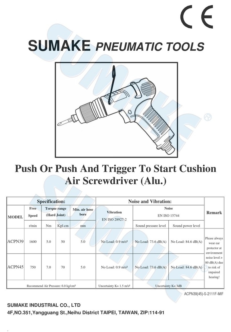
SUMAKE PNEUMATIC TOOLS
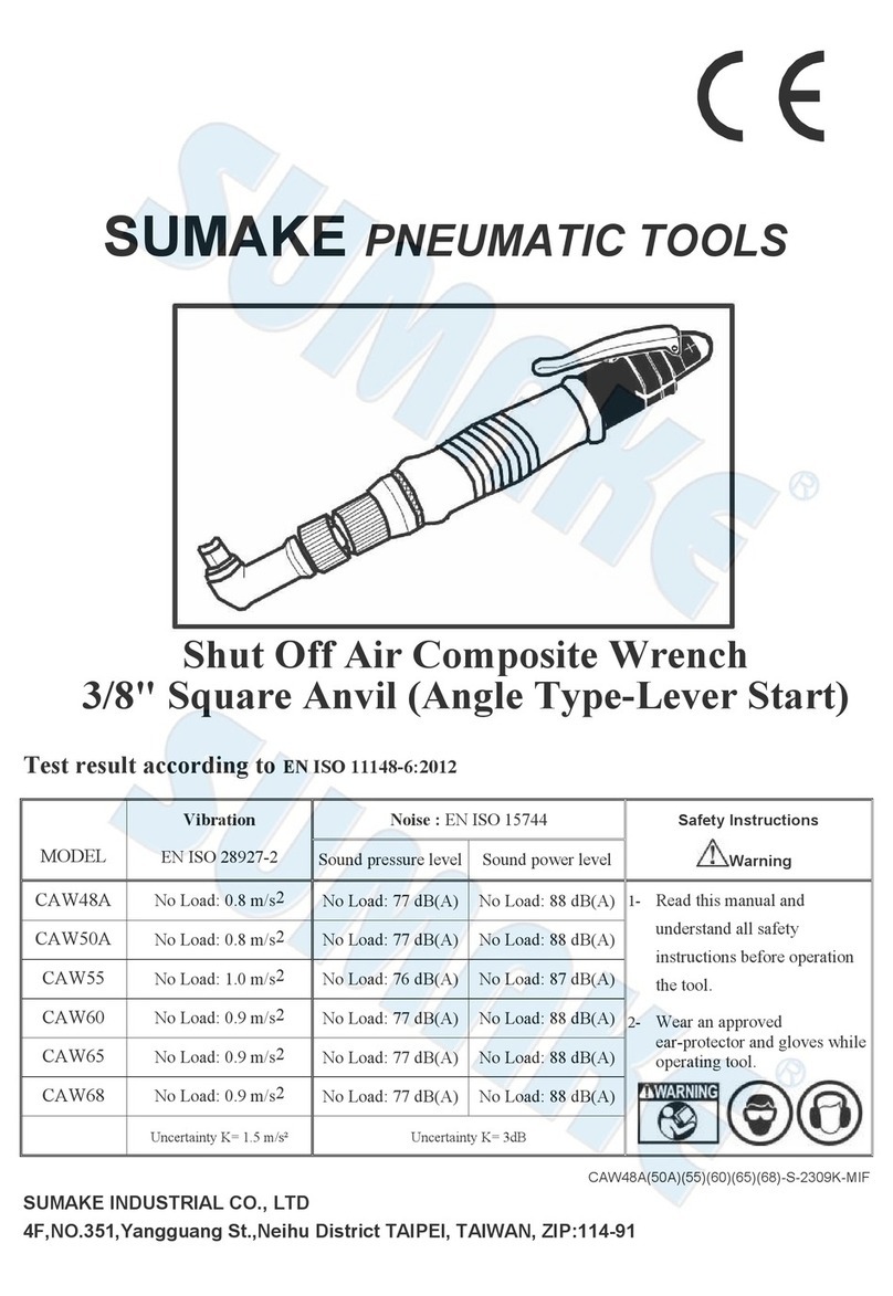
Shut Off Air Composite Screwdriver
(Angle Type-Lever Start)
Test result according to EN ISO 11148-6:2012
MODEL
Vibration
EN ISO 28927-2
Noise : EN ISO 15744
Safety Instructions
Warning
Sound pressure level
Sound power level
CA10
No Load: 0.4 m/s2
No Load: 68 dB(A)
No Load: 79 dB(A)
1- Read this manual and
understand all safety
instructions before operation
the tool.
2- Wear an approved
ear-protector and gloves while
operating tool.
CA20
No Load: 0.9 m/s2
No Load: 75 dB(A)
No Load: 86 dB(A)
CA30
No Load: 0.9 m/s2
No Load: 75 dB(A)
No Load: 86 dB(A)
CA35
No Load: 0.9 m/s2
No Load: 75 dB(A)
No Load: 86 dB(A)
CA38
No Load: 0.9 m/s2
No Load: 75 dB(A)
No Load: 86 dB(A)
CA40
No Load: 0.9 m/s2
No Load: 75 dB(A)
No Load: 86 dB(A)
CA45
No Load: 1.1 m/s2
No Load: 73 dB(A)
No Load: 84 dB(A)
Uncertainty K= 1.5 m/s²
Uncertainty K= 3dB
CA10(20)(30)(35)(38)(40)(45)-S-2301G-MIF
CA11.21.35.38.41.46-S-0503A-MI
SUMAKE INDUSTRIAL CO., LTD
4F,NO.351,Yangguang St.,Neihu District TAIPEI, TAIWAN, ZIP:114-91

EC DECLARATION OF CONFORMITY
We: SUMAKE INDUSTRIAL CO., LTD.
4F, No. 351, Yangguang St., Neihu District, Taipei City, Taiwan
declare in sole responsibility that the equipment
Equipment:SHUT OFF AIR COMPOSITE SCREW DRIVER(ANGLE TYPE-LEVER START)
Model/ Serial No.:CA10(20)(30)(35)(38)(40)(45)
to which this declaration applies, complies with these normative documents:
Machinery Directive: 2006/42/EC
and conforms to the following EN standard,
EN ISO 12100: 2010
EN ISO 11148-6:2012
Name and Signature/Position Date and Place
2021/12/1
Mike Su –Managing Director Taipei, Taiwan
CA10(20)(30)(35)(38)(40)(45)-D-2301F-MIF

AIR SCREWDRIVER OPERATION MANUAL
For safety use, Please Follow the instructions. The operation without your local regulations may cause serious injury.
Read thoroughly and understand this instruction manual and keep this within reach for future reference.
CLASSIFIED CAPACITY SPECIFICATIONS Fastening CapacityFree
Speed Weight
O.A.L
Dia.
Air
Pressure Min. air
hose bore Air
Consumption Torque
range Standard
Deviation
Model
No. r.p.m. g mm mm Kg/cm²mm m³/min Kgf-cm % Machine
Screw Dia. Tapping
Screw Dia.
CA20 1000 660 270 31 6.0 5.0 0.2 1-8 ±3 M1.7-M3.3 M1.3-M2.7
CA30 1800 660 270 31 6.0 5.0 0.28 3-17 ±3 M2.2-M4.2 M1.7-M3.2
CA35 2200 660 270 31 6.0 5.0 0.28 3-20 ±3 M2.2-M4.5 M1.7-M3.5
CA38 1800 660 270 31 6.0 5.0 0.28 3-25 ±3 M2.2-M4.7 M1.7-M3.8
CA40 1000 660 270 31 6.0 5.0 0.28 5-30 ±3 M2.8-M5.0 M2.3-M4.0
CA45 800 660 270 31 6.0 5.0 0.3 8-40 ±3 M3.3-M5.7 M2.7-M4.4
CA48 1700 1100 315 39 6.0 8.0 0.55 5-45 ±3 M2.8-M5.8 M2.2-M4.7
CA50 1400 1100 315 39 6.0 8.0 0.55 7-50 ±3 M2.9-M6.0 M2.6-M4.9
CA55 1000 1200 235 39 6.0 8.0 0.55 7-65 ±3 M2.9-M6.4 M2.6-M5.4
CA60 550 1200 235 39 6.0 8.0 0.55 15-95 ±3 M4.1-M7.0 M3.1-M6.0
CA65 300 1400 235 39 6.0 8.0 0.55 30-180 ±3 M5.0-M9.3 M4.0-M7.2
CA68 250 1400 235 39 6.0 8.0 0.55 50-280 ±3 M6.0-M11.0 M4.9-M8.7
OPERATIONS
1. Precision adjustment has been made around case, gear and rotating section.
2. Smooth change of valve reverse (right/left) button turn direction can be done.
3. Push valve reverse button makes instantly change direction of air motor rotation.
4. Lever-to-Start system eliminates troublesome to press push-to-Start.
5. Easy adjusting fastening torque by tightening or loosening nut torque indication.
Tighten to the right: increase torque. Loosen to the left: decrease torque
6.Air motor will automatically stop when the load reaches at the pre-set torque
AIR SUPPLY
1. Air tools are adversely affected by moisture. Since air from compressor contains much moisture and dust,
it is desirable to provide a filter and lubricator in the pipeline to remove such undesirable elements. Also
take the drain out from air tank every day.
2. When using brand-new air hose or air pipe. Blow and clean the inside of air hose or pipe before
installation.
3. Keep inside of air hose or air pipe clean to prevent airdrop problem caused by the lots of drain and dust
accumulated and possibly make the inside diameter smaller in the long use.
4. When disconnect air hose from air tool while in the operation do not drop air hose end to the floor as dust
or other element may come into air hose.
5. Use air regulator to keep stable air pressure at 5.5kg/cm2-6.0kg/cm2at the toll. It is important to get
proper air pressure at the toll.
6. After lubrication, oil will discharged the exhaust upon operation. Flush motor for a few seconds.
LUBRICATION
1.Lubrication is indispensable to air tolls. The most ideal maintenance is to install one lubricator
to a toll for automatic oil feed, but if it is not available, manual lubrication twice every
day is recommended for longer life and keeping the efficient function of mechanism.
2.For manual lubrication, disconnect air hose from bushing air inlet and full up spindle
oil (#40-#60) into the air feed in take and push the bit.
CA20(30)(35)(38)(40)(45)(48)(50)(55)(60)(65)(68)-I-1106G-MI
Silencer
Color Ring
Air Inlet Oil Dail
y
Lever
Valve reverse
Rear housing
Tor
q
ue Indication Rin
g

CA30
CA30-P-2307C-MI
SHUT OFF AIR COMPOSITE SCREW DRIVER (ANGLE TYPE-LEVER START)

CA30
PARTS LIST
No. Parts No. Description Q'ty No. Parts No. Description Q'ty
1 5A3037 End Housing 1 43 6N2105 Spring 1
1-1 2S3010 Inner Bushing 1 44 2P3020 Silencer 1
1-2 2S3001 Outer Bushing 1 45 5A2001 Lever Set 1
2 7Q2017 Valve O-Ring 1 46 5L3102 Lever 1
2-1 6N2108 Spring 1 47 7S2202 Roll Pin 1
3 6S2203 Valve 1 48 2Q5001 O Ring 1
4 7S2108 Set Screw And Washer 1 2S2010 Air Inlet Bushing [PT] 1
4-1 2U3001 Switch Bushing 1 2S6005 Air Inlet Bushing [PS] 1
52L3021 Switch 1 2S2007 Air Inlet Bushing [NPT] 1
6 7S2001 Ball Bearing 1 50 2S2103 Retainer 1
7 1S3001 End Plate 1 51 7S2102 Ball 28
10 1P3005 Cylinder 1 52 3S2001 Pilot Pin 1
10-1 7S5204 Roll Pin 1 53 3S2211 Rear Clutch 1
12 1P3050 Blade 5 54 6N2006 C Ring 1
13 1P3065 Front Plate 1 55 3S2215 Center Clutch 1
14 7S2031 Ball Bearing 1 56 7S2112 Ball 2
14-1 7S2007 Ball Bearing 1 57 3S7035 Anvil 1
16 1S3043 Rotor 1 57-1 7Q2002 Regulate Screw 1
18 1G6279 18T Main Gear 1 58 7S2105 Ball 2
18-1 2S5134 Washer 1 59 6N2110 Spring 1
19 1P2110 12T Plate Gear 8 60 3S2226 Slide Base 1
20 1P3274 Third Gear Cage and Main Gear 161 3S2222 End Clutch 1
23 1P2284 Third Gear Cage 1 62 7S2102 Ball 22
24 1S2061 Internal Gear 1 63 3S2231 Ball Race 1
25 5A3024 Center Housing 1 64 6N3100 C Ring 1
26 7S5003 Ball Bearing 1 65 6N5008 Torque Spring 1
27 7Q2015 O Ring 1 66 2S7121 Washer 1
28 2S2104 Washer 1 67 3S3549 Bushing 1
28-1 2P3013 Silencer 1 68 2S2240 Anvil Bushing 1
29 2A3001 Exhaust Deflector 1 69 3S3121 Angle Clutch Housing 1
30 7Q2007 O Ring 1 70 6S2010 Needle Pin 3
31 6S6109 Valve Plate 1 71 3S3101 Regulation Washer 1
32 6S2009 Operating Rod 1 72 3S3002 Torque Ring 1
33 6N2101 Cone Spring 1 75 5A3519 Torque Cover 1
34 6S2031 Screw 1 75-1 2Q2003 O-Ring (23x2) 1
35 7S2113 Screw 1 76 6N3102 Spring 1
36 6N2133 Spring 1 77 7S2219 Screw 1
37 2S2507 Valve Pin 1 78 7S2102 Ball 2
38 7Q2003 Valve O-Ring 1 79 7S5108 Screw 1
39 6S2031 Screw 1 81 5S2020 Housing Set 1
40 7S2213 Screw 1 82 6N2103 Angle Lock Nut 1
41 7Q6100 O Ring 1 83 5C2028 Angle Head Assembly 1
42 7S2109 Ball 1 83-1 6N5112 Spring 1
CA30-P-2307C-MI
SHUT OFF AIR COMPOSITE SCREW DRIVER (ANGLE TYPE-LEVER START)
49

SCREWDRIVER
Original instructions
SUMAKE Industrial Co. Ltd.

Read all these safety instructions before operating this product and save these instructions.
The tool has been manufactured in conformity with the instruction of EU machine directive. The EU mark will be considered void in the
event of inexpert repairs, the use of non-original parts and in case of non-observance of the safety instructions in the user’s manual.
Possible direct or indirect consequential damages are not the responsibility of SUMAKE Industrial co., Ltd.
General safety rules:
1. Watch the tool at all times when in use.
2. People under the influence of alcohol or drugs are not allowed to use, repair or maintain the tool.
3. Keep unqualified persons, children, etc. away from the tool.
4. Keep work area clean and with sufficient daylight or artificial lighting. The work area on which the machine is used must be cleaned up.
Disorder is a potential cause of accidents.
5. Danger of explosion. Never use oxygen and combustible gas as an air supply for the tool which may be ignited by spark and cause
fire or explosion.
6. Never use gasoline or other flammable liquids to clean the tool.
7. Do not use air tools in potentially explosive atmospheres such as in the presence of flammable liquids, cleaning solvents, fluid energy
or stored gases.
8. Do not expose air tools to rain. Do not use air tools in damp or wet locations.
9. When a fault or failure is detected, the tool must immediately be disconnected from the air supply and returned for repair.
10. When not in use, keep tools in a dry place, either locked up or in a high place, out of the reach of children.
11. Do not force small air tools to do the job of a heavy –duty task. Do not use air tool for purpose of which was not intended.
12. Wear suitable ear protection at environment noise level >80dB(A) and safety spectacles when using the tool. Always wear approved
safety goggles if work in dusty. This also applies to other persons in the nearby vicinity.
13. Do not wear loose clothing or jewelry. They can be caught in moving parts. Rubber gloves and non-skid foot wear are recommended
when working outdoors. Wear protective hair covering to contain long hair.
14. Keep proper footing and balance at all times.
15. Use clamps or a vice to hold work-piece. It is safer than using your hand and free both hands to operate the air tool.
16. When not use, before performing service or changing accessories, please disconnect tool from air compressor.
17. Do not carry plugged in air tool with your finger on the switch trigger. Be sure switch is in the “OFF” position when connecting to air
supply.
18. Watch what you are doing. Use common sense, even unsafe situation or unbalanced positions, particularly when you are tired.
19. Air powered tools can vibrate in use. Vibration, repetitive motions or uncomfortable positions may be harmful to your hands or arms.
Stop using any tool if discomfort, tingling feeling or pain occurs. Seek medical advice before resuming use.
20. For multiple hazards, read and understand the safety instructions before installing, operating, repairing, maintaining, changing
accessories on, or working near the assembly power tool for threaded fasteners. Failure to do so can result in serious bodily injury.
21. Only qualified and trained operators should install, adjust or use the assembly power tool for threaded fasteners.
22. Do not modify this assembly power tool for threaded fasteners. Modifications can reduce the effectiveness of safety measures and
increase the risks to the operator.
23. Do not discard the safety instructions; give them to the operator.
24. Tools shall be inspected periodically to verify that the ratings and markings required by this part of EN ISO 11148 are legibly marked
on the tool. The employer/user shall contact the manufacturer to obtain replacement marking labels when necessary.
Safety precautions for projectile hazards
1. Failure of the workpiece, of accessories or even of the inserted tool itself can generate high-velocity projectiles.
2. Always wear impact-resistant eye protection during the operation of the assembly power tool for threaded fasteners. The grade of
protection required should be assessed for each use.
3. Ensure that the workpiece is securely fixed.
Safety precautions for entanglement hazards
1. Entanglement hazards can result in choking, scalping and/or lacerations if loose clothing, personal jewellery, neckware, hair or gloves
are not kept away from the tool and accessories.
2. Gloves can become entangled with the rotating drive, causing severed or broken fingers.
3. Rotating drive sockets and drive extensions can easily entangle rubber-coated or metal-reinforced gloves.
4. Do not wear loose-fitting gloves or gloves with cut or frayed fingers.
5. Never hold the drive, socket or drive extension.
6. Keep hands away from rotating drives.
Safety precautions for operating hazards
1. The use of the tool can expose the operator's hands to hazards including crushing, impacts, cuts and abrasions and heat. Wear
suitable gloves to protect hands.
2. Operators and maintenance personnel shall be physically able to handle the bulk, weight and power of the tool.
3. Hold the tool correctly; be ready to counteract normal or sudden movements and have both hands available.
4. Maintain a balanced body position and secure footing.
5. Release the start-and-stop device in the case of an interruption of the energy supply.
6. Use only lubricants recommended by the manufacturer.
7. Do not use in confined spaces and beware of crushing hands between tool and workpiece, especially when unscrewing.
Safety precautions for repetitive motions hazards
1. When using a power tool, the operator can experience discomfort in the hands, arms, shoulders, neck, or other parts of the body.

2. While using an assembly power tool for threaded fasteners, the operator should adopt a comfortable posture whilst maintaining secure
footing and avoiding awkward or off-balanced postures. The operator should change posture during extended tasks, which can help
avoid discomfort and fatigue.
3. If the operator experiences symptoms such as persistent or recurring discomfort, pain, throbbing, aching, tingling, numbness, burning
sensations or stiffness, these warning signs should not be ignored. The operator should tell the employer and consult a qualified health
professional.
Safety precautions for accessory hazards
1. Disconnect the assembly power tool for threaded fasteners from the energy supply before changing the inserted tool or accessory.
2. Use only sizes and types of accessories and consumables that are recommended by the assembly power tool for threaded fasteners
manufacturer.
Safety precautions for workplace hazards
1. Slips, trips and falls are major causes of workplace injury. Be aware of slippery surfaces caused by the use of the tool and also of trip
hazards caused by the air line or hydraulic hose.
2. Proceed with care in unfamiliar surroundings. Hidden hazards, such as electricity or other utility lines, can exist.
3. The assembly power tool for threaded fasteners is not intended for use in potentially explosive atmospheres and is not insulated
against coming into contact with electric power.
4. Make sure there are no electrical cables, gas pipes, etc., that can cause a hazard if damaged by use of the tool.
Safety precautions for dust and fume hazards
1. Dust and fumes generated when using assembly power tools for threaded fasteners can cause ill health (for example, cancer, birth
defects, asthma and/or dermatitis); risk assessment and implementation of appropriate controls for these hazards are essential.
2. Risk assessment should include dust created by the use of the tool and the potential for disturbing existing dust.
3. Direct the exhaust so as to minimize disturbance of dust in a dust-filled environment.
4. Where dust or fumes are created, the priority shall be to control them at the point of emission.
5. All integral features or accessories for the collection, extraction or suppression of airborne dust or fumes should be correctly used and
maintained in accordance with the manufacturer's instructions.
6. Use respiratory protection in accordance with employer's instructions and as required by occupational health and safety regulations.
Safety precautions for noise hazards
1. Unprotected exposure to high noise levels can cause permanent, disabling, hearing loss and other problems, such as tinnitus (ringing,
buzzing, whistling or humming in the ears).
2. Risk assessment and implementation of appropriate controls for these hazards are essential.
3. Appropriate controls to reduce the risk may include actions such as damping materials to prevent workpieces from “ringing”.
4. Use hearing protection in accordance with employer's instructions and as required by occupational health and safety regulations.
5. Operate and maintain the assembly power tool for threaded fasteners as recommended in the instruction handbook, to prevent an
unnecessary increase in noise levels.
6. If the assembly power tool for threaded fasteners has a silencer, always ensure it is in place and in good working order when the
assembly power tool for threaded fasteners is operating.
7. Select, maintain and replace the consumable/inserted tool as recommended in the instruction handbook, to prevent an unnecessary
increase in noise.
Safety precautions for vibration hazards
1. Exposure to vibration can cause disabling damage to the nerves and blood supply of the hands and arms.
2. Wear warm clothing when working in cold conditions and keep your hands warm and dry.
3. If you experience numbness, tingling, pain or whitening of the skin in your fingers or hands, stop using the assembly power tool for
threaded fasteners, tell your employer and consult a physician.
4. Operate and maintain the assembly power tool for threaded fasteners as recommended in the instruction handbook, to prevent an
unnecessary increase in vibration levels.
5. Select, maintain and replace the consumable/inserted tool as recommended in the instruction handbook, to prevent an unnecessary
increase in vibration levels.
6. Sleeve fittings should be used where practicable.
7. Support the weight of the tool in a stand, tensioner or balancer, if possible.
8. Hold the tool with a light but safe grip, taking account of the required hand reaction forces, because the risk from vibration is generally
greater when the grip force is higher.
Additional safety instructions for pneumatic power tools
1. Always shut off air supply, drain hose of air pressure and disconnect tool from air supply when not in use, before changing accessories
or when making repairs.
2. Never direct air at yourself or anyone else.
3. Whipping hoses can cause severe injury. Always check for damaged or loose hoses and fittings.
4. Cold air shall be directed away from the hands.
5. Whenever universal twist couplings (claw couplings) are used, lock pins shall be installed and whipcheck safety cables shall be used to
safeguard against possible hose-to-tool and hose-and-hose connection failure.
6. Do not exceed the maximum air pressure stated on the tool.
7. For torque-control and continuous-rotation tools, the air pressure has a safety critical effect on performance. Therefore, requirements
for length and diameter of the hose shall be specified.
8. Never carry an air tool by the hose.


General preparation and connection:
1. When using brand-new air hose or air pipe. Blow and clean the inside of air hose or pipe before installation.
2. Keep inside of air hose or air pipe clean to prevent airdrop problem caused by the lots of drain and dust accumulated and possibly
make the inside diameter smaller in the long use.

3. Before connecting the air hose, apply 4 to 5 drops of SAE(#40-#60) spindle oil at the air inlet. Also, every 3 to 4 hours of operation,
oiling is necessary. Twist Teflon thread tape to ensure a proper seal air inlet. Then tighten the air coupler into air tool.
4. The supplied compressed air must be clean and dry, with the appropriate oil mist. Use an air treatment unit; filter, regulator and
lubricator.
5. Please refer Fig.1 illustration shows the correct mode of connection to the air supply system which will increase the efficiency and
useful life of the tool.
6. The quick connect coupling and hose must have sufficient air flow capacity. We recommend an air hose with a diameter of 5mm for
small body, 8mm for big body.
7. To ensure a good performance. The operation pressure at the compressed air inlet should not exceed 6.3bar (90psi) (unless

indicated otherwise). Higher operating pressures may cause damaged or excessive wear. Operating pressures below 5.3bar may

cause pressure or power loss.
Risk of injury
1. Compressed air can inflict serious injuries. Therefore never point the air hose at another person or yourself.
2. Shut –off the air supply and disconnect the tool in case:
➢You want to change or replace accessories.
➢You want to clean, repair or maintain the tool.
➢The tool is not going to use for some times.
3. Check compressed air hose before use. If it is damaged, broken, torn, or deformed, the hose is not to be connected to the tool.
4. Always check the pneumatic couplings before using the tool. If they show signs of damage, fracture, cracking or excessive corrosion,
the respective tool or the air hose is not to be used.
5. Use only qualified adapters and connectors, In case of wear they are to be replaced immediately.
6. Only use air pipes that are fit for the use at maximum pressure.
Maintenance instruction:
1. Dry the filter (fig1) and the air inlet of the tool.
2. Lubricate the quick connect coupling to prevent blocking.
3. Air tool require lubrication throughout the life of the tool. The air motor and bearing uses compressed air to start the tool. The moisture
in compressed air will rust the air motor; you must lubricate the motor daily.
4. Avoid storing the tool in a location subject to high humidity. If the tool is left as it is used, the residual moisture inside the tool can
cause rust.
5. Before storage, lubricate tool and run it for a few seconds.
6. Regular inspection of spindles, threads, and clamping devices in respect of wear and tolerances for location of abrasive products.
7. If the tool is too seriously damage to be used anymore, recycle raw material instead of disposing as waste. The machine, accessories
and packaging should be sorted for environmental-friendly recycling. Check with your local authority or retailer for recycling advice.
SCREWDRIVER-I-202112B
This manual suits for next models
5
Table of contents
Other Sumake Power Screwdriver manuals

Sumake
Sumake ST-4450 User manual

Sumake
Sumake APP48 User manual

Sumake
Sumake ADPN39 User manual

Sumake
Sumake ADPN48 User manual

Sumake
Sumake ABP48 User manual

Sumake
Sumake SMNP48/O.E. User manual

Sumake
Sumake CP12 User manual

Sumake
Sumake CAW48A User manual

Sumake
Sumake APP35 User manual

Sumake
Sumake APS39 User manual

Sumake
Sumake CA48 User manual

Sumake
Sumake SMPR48/O.E. User manual

Sumake
Sumake SMT-30A User manual

Sumake
Sumake HAFH030 User manual

Sumake
Sumake CBP35 User manual

Sumake
Sumake CS39 User manual

Sumake
Sumake CPP35 User manual

Sumake
Sumake ACPN48 User manual

Sumake
Sumake SMNP10/O.E. User manual

Sumake
Sumake CL10 User manual