Sundrape Star Elektra User manual

Schalt und
Installationsplan
zur Steuerung
von A2, Plafond
Tandem und 5060
Anlagen
L1 PE N
Zuleitung 220V
supply 220V 50/60Hz
Achtung !
Nur fuer VDE Motore
attention !
3x1,5
Zuleitung 220V
supply 220V 50/60Hz
Abzweigdose
junctionbox
for VDE motors only
Abzweigdose
junctionbox wireing and
and connection
for system of
A2, Plafond
Tandem and 5060
paralellschalten von
Motore ist auf jeden
Fall zu vermeiden !!!
5x1,57x1,54x1,5
Schalter
switch
Motor mit
Endschalter
motor with
limitswitch
Motor ohne
Endschalter
motor without
limitswitch
Motor ohne
Endschalter
motor without
limitswitch
Schalter
switch
Motor mit
Endschalter
motor with
limitswitch
do not connect motors
paralell !!!
sundrape®
Electro drive Vertical blinds
End position adjustment and junction
Schalt und
Installationsplan
zur Steuerung
von einem Motor
Achtung !
Nur fuer VDE Motore
L1 PE N
Zuleitung 220V
supply 220V 50/60 Hz
3x1,5
Zuleitung 220V
supply 220V 50/60 Hz
Abzweigdose
junctionbox
Abzweigdose
attention !
for VDE motors only
wireing and
and connection
( A1, Vorhangzug,
Elmatic, Singlemotor )
for one motor.
( A1, curtain track
Elmatic, singlemotor )
paralellschalten von
Motore ist auf jeden
junctionbox
4x1,54x1,5
Schalter
switch
M
Motor
Schalter
switch
Motor
Fall zu vermeiden !!!
do not connect motors
paralell !!!
Schalt und
Installationsplan
Achtung !
Nur fuer VDE Motore
attention !
L1 PE N
Zuleitung 220V
supply 220V 50/60 Hz
3x1,5
Zuleitung 220V
supply 220V 50/60 Hz
Abzweigdose
junctionbox
Abzweigdose
junctionbox
for VDE motors only
zur Steuerung
von 2 Motoren mit
2 poligen Schalter
wireing and
and connection
( A1, Vorhangzug,
Elmatic, Singlemotor )
diagram for 2 motors
with 2 pole switch
paralellschalten von
( A1, curtain track
Elmatic, singlemotor )
Motor
7x1,5
4x1,5
Schalter
switch
MM
Schalter
switch
Motoren
Motore ist auf jeden
Fall zu vermeiden !!!
do not connect motors
paralell !!!
The motors must not be
connected in parallel!
The motors must not be
connected in parallel!
The motors must not be
connected in parallel!
switching and installation diagram
for the control of one motor
(Star Electra A1 and corvus)
switching and installation diagram for
the control of 2 motors with 2-polar
switch (Star Electra A1 and corvus)
switching and installation
diagram for the control of
Star Electra A2 and plafond
Star Elektra
Star Elektra
with special rail
Corvus
sundrape®, registered trademark of Sundrape GmbH
Subject to technical modifications.
07.2009
Sundrape GmbH • Im Wiebusch 4-6 • 27607 Langen-Sievern • Tel.: (0049) 0 47 43 / 8 94 - 0 • Fax: 0 47 43 / 8 94 - 2 30
Attention! Please do not miss to read!
Please read the instructions for use carefully. In case of damages that have been caused
by disregard of the instructions for use, the guarantee expires. For consequential damages
resulting of it, we do not assume any responsibility.
1.Important security advices
Attention – to assure the security of persons, it is absolutely necessary to observe these instructions.
The instructions have to be filed. Children are not allowed to play with stationary control systems, remote control
devices have to be kept away from children. The system has to be controlled frequently on signs of wear or
damaged cables.
2. Important security instructions for mounting: ATTENTION – wrong mounting may lead to severe injurier.
Observe all - mounting instructions – particularly the connection instructions on page 4.
4x0,75
3x1,5
4x1,5
3x1,5
4x0,75 4x0,75
7x1,5
3x1,5
4x1,5 7x0,75 5x0,75
MM

Data motor plug: Technical data:
type TK3 = 4 pole voltage rating 230 V 110 V
TK5 = 6 pole nominal rating abt 30 W 30 W
voltage 230 VAC rated current 0,13 A 0,26 A
fuse protection 10 A frequency 50 Hz 60 Hz
system of protection IP 30 operation mode S3 50 % S3 50%
group of isolation B direction of rotation ri + le ri + l
for dry rooms only
*) test cable type A1 order No. 206 820
test cable type A2 order No. 206 821
No warranty if these instructions are not followed. Subject to technical modifications.
End position installation of assembled sundrape electro drives
Drive runner approximate-
ly in centre of rail. Release
screws in cover lid and
remove them in direction
of arrow. Now you can see
the two buttons for the
end positions.
1. Push safety clip to the
back and press button I
down. Turn button I (both
directions possible) until
all three grooves of index
rings are visible in one line
and switch noise of the microswitch becomes audible.
2. Connect test cable* and switch on for the inactive direction of movement. When the motor starts
going, choose other switching position at the test cable.
ATTENTION!
Setting of the end positions is made with buttons I and II only - Turn button I by hand (both direc-
tions possible) until motor starts running. Hold button I until runners have assembled to a distance
between each other of abt. 10 mm. Attention: with Corvus blinds it is essential to watch a
safety distance of 10 mm (side of stack). First end position is set.Turn off operating switch
3. Pull out button I carefully without turning and let it click into place.
4. To set second end position, push safety handle across centre position, press button II. Turn but-
ton II (both directions possible) until all three grooves of index rings are visible in one line and switch
noise of microswitch is heard.
5. Turn on operating switch for opposite running direction. Turn button II by hand (both directions
possible) until motor starts running. Hold button II until first runner has reached a distance of half the
width of a louvre to the end of the blind. Attention: with Corvus blinds drive onto the snapper
and do not go beyond this position. Second end position is reached. Switch off operating switch.
6. Pull out carefully button II without turning it and let it engage.
7. Shift safety handle precisely to the middle and fix lid.
8. Test both setting and re-adjust, if necessary.
Attention: with tandem blinds one motor only is set.
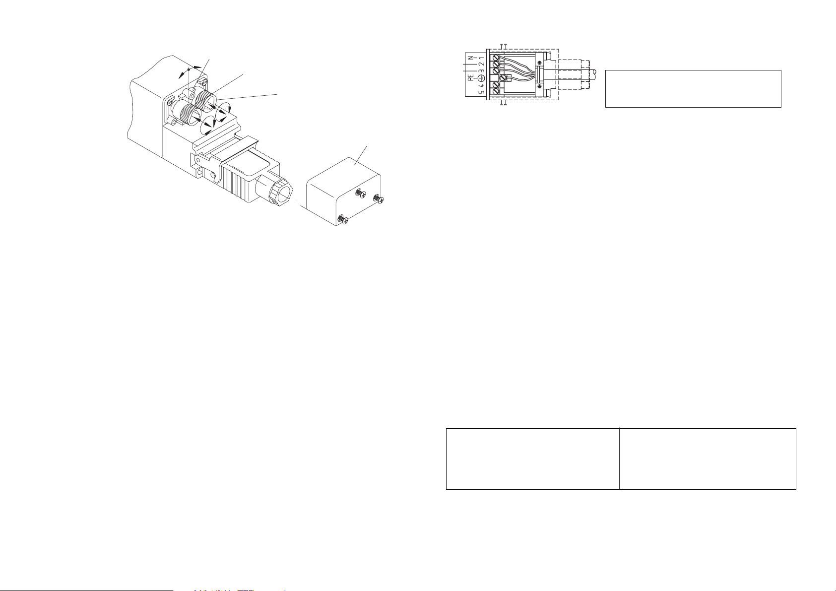
N = neutral conductor (neutral blue)
right-handed rotation = control wire (right brown)
left-handed rotation = control wire (left black)
PE = protective conductor (PE yellow/ green)
Instruction for electrical connection of
sundrape® electric vertical blinds
Before installation of the electric drive, all unne-
cessary wires are to be taken away and existing
installations which are not necessary for a use
with electric supply are to be deactivated. When
mounting electric drives which are operated by
touch contact switch, the touch contact switch
has to be installed near the system, however at a
safety distance to moving parts and above a
height of 1,5 m. For drives delivered without
moving parts, the reference turning moment and
the reference working duration have to be com-
patible with the characteristics of the running
part.. Do not exceed the maximum turning
moment. In case you need more detailed infor-
mation, please contact the manufacturer.
Connections and supply lines to be installed at
the building-site by authorized electro-firms in
compliance with offical regulations. In order to
avoid backing ups of currents in the condensers
of running motors, operate the motors separate-
ly. A separate contact for each rotation direction
of the motors is required (for decoupling purpo-
ses). For controls of more than 2 motors a group
control is required. . Control types for sundrape
electro blinds:
single
in groups with central control
by radio remote control
automatic and central control
Cable laying plans and wiring diagrams are sub-
mitted on request.
3/right-handed rotation
2/left-handed rotation
safety clip
button I
button II
cover

!
Safety instructions
Before starting sundrape®electric motors, group con-
trols and radio remote controls carefully read technical
instructions for connexion, mounting and operation.
In case of damages caused by disregarding these
instructions, the guarantee expires. For consequential
damages we do not
assume any responsibility.
Attention – to assure the security of persons and facili-
ties these instructions have to be observed absolutely!
File the instructions carefully!
This device is not designed for employees (including
kids) with limited physical or mental skills or sensory
perception or for persons with a lack of experience or
knowledge, unless they are supervised by a person who
is responsible for their security or unless they received
instructions how to use the device.
Children are not allowed to play with stationary con-
trols and electrical systems. Keep radio remote control
devices away from children! Kids should be watched to
make sure that they do not play with the device.
The system has to be checked regularly on signs of
wear or damaged electrical lines.
Attention – inadequate mounting can cause severe
injuries!
Before you start maintenance work on electrical blinds,
always cut off power supply. The same applies to win-
dow cleaning work, if contact of humidity and cleaning
agents with the electrical systems is possible.
Connexion instructions for
sundrape®electric motors
Connexions and supply lines have to be passed
on site by authorized electricians according to
VDE (German Electrical Engineering Association)
and local EVU (electric supply company) instruc-
tions.
For controls of two and more motors a group con-
trol is required. Cable laying plans and wiring
diagrams for group and central controls as well
as remote controls can be submitted on request.
Switch off unused lines and systems before you
connect the motor. Place push-buttons above a
height of 1,5 m near the system.
Allowed running periods and torques have to cor-
respond with the motor’s technical data.
In order to avoid backing ups of condensers
of running motors, parallel connexion of two
or more motors at one exit is prohibited. For
decoupling purposes a separate contact for
each direction of rotation is required.
Use only mechanically or electrically locked
switches and push-buttons. Switches and
controls may not permit concurrent up and
down operation! The time to change the run-
ning direction from up/down to down/up has
to be at a minimum of 0,5 seconds. This
applies also for programmable control devi-
ces.
This manual suits for next models
1