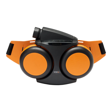
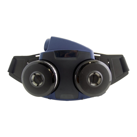
Sundstrom SR 700 User manual

2019-06-04
OI06H-7018 SR 700 1
Operating instructions
SR 700
Revision: 04

General information
Instructions for use for SR 700 should be read before use.
The SR 700 is a battery-powered fan that is included, together with the particle filter and approved head top, in
the Sundström respiratory protective system conforming to EN 12941/12942:1998
Available head tops for the SR 700 are listed in Instructions for use.
When selecting filters and head top, the following are some of the factors that must be taken into account:
▪Types of pollutants
▪Concentrations
▪Work load
▪Protection requirements in addition to respiratory protection
The risk analysis should be carried out by a person who has suitable training and experience in the area.
2019-06-04
OI06H-7018 SR 700 2

Unpacking the SR 700
Packing list:
•Fan unit SR 700
•Battery SR 701
•Battery charger SR 713
•Belt SR 508
•Particle filter SR 510 P3 R, 2x
•Filter adapters, 2x
•Pre-filter holders, SR 511, 2x
•Pre-filters, SR 221, 10x
•Flow meter SR 356
•User instruction
•Cleaning tissue SR 5226
•Plug kit, 3pcs
2019-06-04
OI06H-7018 SR 700 3

1. Assembly, battery
2019-06-04
OI06H-7018 SR 700 4
1.1 Attach the plug to the AC
adapter.
1.2 Remove and charge the
battery.
The charger carries out
charging automatically in
three stages.
1. Orange LED
2. Yellow LED
3. Green LED
1.3 Check that the gasket
round the charge contact in
the fan unit is in place and is
in good condition.
1.4 Push the battery back into
the battery compartment.

2. Assembly belt
2019-06-04
OI06H-7018 SR 700 5
2.1 Assemble the belt by
pressing together the two
halves of the buckle.
2.2 The belt should be
mounted so that the belt is
pointing upwards.
Insert the three tongues of
the belt half into the slot in the
fan.
Begin to insert the upper
tongue and then turn the belt
into the fan.
2.3 Press down the three lips
locking the belt half.
2.4 Correctly mounted belt.

3. Particle filter
2019-06-04
OI06H-7018 SR 700 6
The fan unit may be used with only particle filters P3 R, model
number SR 510 with filter adapter or SR 710, which provides
protection against all types of particles, both solid and liquid.
Read carefully the user instructions accompanying the filters.
Note!
When filters are changed, both filters must be changed at the same
time.
3.1 Check that the gaskets in
the filter mounting of the fan
unit are in place and are in
good condition.
3.2 If particle filter SR 510 are
used, snap it on the filter
adapter without pressing onto
the center of the filter.
3.3 Screw the filter into the
filter mounting so far that the
adapter will be in contact with
the gasket. Then turn it about
1/8 of a turn further in order to
ensure a good seal

2019-06-04
OI06H-7018 SR 700 7
3.4 Fit one pre-filter SR 221
into the pre-filter holder.
Press the pre-filter holder
onto the particle filter
The pre-filters SR 221 protect the main filter against excessively fast
clogging. The pre-filter holders also protect the main filters against
handling damage.
3.5 Correctly mounted pre-
filter holder with particle filter.

4. Operation/Performance
2019-06-04
OI06H-7018 SR 700 8
4.1 Start the fan by pressing
the control button.
4.2 The symbols on the
display will light up and the
sound signal will sound. The
fan starts in normal operating
status. (175 l/min).
4.3 If the button is pressed
again, the flow will increase to
225 l/min, and this is
indicated by the large fan
symbol lighting up.
If the control button is
pressed again, the fan flow
rate will revert to 175 l/min
and the small fan symbol will
again light up.

5. Warning system/alarm signals
2019-06-04
OI06H-7018 SR 700 9
5.1 In the event of air flow
obstructions
A pulsating sound signal will
be heard.
The red warning triangle of
the display will flash.
Action: Immediately interrupt
the work, leave the area, and
inspect the equipment.
If the particle filters are clogged
A continuous sound signal will be heard for five seconds. The red
warning triangle in the display will flash. The warning triangle will
flash continuously, whereas the sound signal will be repeated at
intervals of 80 seconds.
Action: Immediately interrupt the work, leave the area and change the
filter.
5.2 If the battery capacity is
lower than 5 %
A sound signal will be
repeated twice at intervals of
two seconds.
The yellow battery symbol of
the display will flash. The
battery symbol will flash
continuously, whereas the
other signals are repeated at
intervals of 30 seconds until
about one minute remains
before the battery would be
fully discharged. The sound
signal then changes to an
intermittent signal.
Action: Immediately interrupt
the work, leave the area and
change/charge the battery.

6. Performance check, minimum flow
2019-06-04
OI06H-7018 SR 700 10
6.1 Check that the fan unit is
complete, correctly mounted,
thoroughly cleaned and
undamaged
Connect the hose from the
head top to the fan and turn it
about 1/8 of a turn clockwise.
6.2 Turn the flow meter bag
inside out so that the
transparent measuring tube is
on the outside.
Note. If the bag is turned with
the measuring tube inwards,
it can be used as a storage
bag.
.
6.3 Place the head top in the
flow meter bag and start the
fan unit.
Grip the lower part of the bag
in order to seal around the
hose.
Grip around the measuring
tube and hold the tube
vertical.
The ball should now float
level with or just over the
175 l/min marking.
If the minimum flow is not
achieved, check that:
-The flow meter is vertical
-The ball moves freely
-The bag seals well around
the hose.

7. Performance check, alarms
2019-06-04
OI06H-7018 SR 700 11
The equipment is designed to provide a warning if the air flow is
obstructed, and this should be checked in conjunction with the
flow. Check before the equipment is taken into use.
N.B. If the minimum flow is not achieved or if the alarm signals
do not operate as intended, the fan must not be used.
7.1 Cause a flow stoppage
by still holding tightly the joint
between the hose and the
flow meter bag and then
blocking off the flow meter
outlet.
7.2 The fan will now initiate
an alarm by audible and
visual signals.
7.3 If the flow meter outlet is
now unblocked and the air is
allowed to flow freely, the
alarm signals will cease
within 10 –15 seconds.
Switch off the fan and remove
the head top from the flow
meter bag.

8. Putting the equipment on
2019-06-04
OI06H-7018 SR 700 12
Before putting the equipment on, read carefully the user
instructions for the head top.
After the filter has been fitted, a performance check has been
carried out and the head top has been connected, the equipment
can be put on.
8.1 Snap the two ends of the
belt together.
After the buckles have been
connected, tighten the belt so
that it is comfortable.
8.2 The fan should be firmly
in contact with the wearer’s
back in order to ensure
optimum comfort and
ergonomic benefits.
8.3 Put the belt ends in the
clips on each side of the belt.
Start the fan.
Put the head top on.

2019-06-04
OI06H-7018 SR 700 13
8.5 Make sure that the
breathing hose runs along
your back and is not twisted
8.6 Note that when a full face
mask SR 200 is used, the
hose should run along your
waist and up along the chest.
When a half mask SR 900 is
used, the hose should run
along your back and over
your shoulders.
Hose SR 951
Hose SR 952

9. To change the particle filters
2019-06-04
OI06H-7018 SR 700 14
9.1 Unscrew the filters.
Release the filter holders.
Bear in mind that both filters
must be changed at the same
time.
9.2 Remove the filter adapter
from SR 510.
9.3 Change the pre-filters in
its holders. Clean, as
necessary.
9.4 Fit new filters.

10. Cleaning/Disinfection
2019-06-04
OI06H-7018 SR 700 15
10.1 The plug kit is used for
cleaning or decontamination
of the fan unit and prevents
dirt and water from entering
the fan housing.
Disconnect the breathing
hose and the filters and install
the plugs.
10.2 In the event of heavy
fouling, a soft brush or
sponge wetted with a solution
of water and dishwashing
detergent can be used.
.
10.3 A SR 5226 cleaning wipe
should be used for daily
cleaning.
Wipe the outside of the fan.
If necessary, spray the product with 70 % ethanol or isopropanol
solution for disinfection.

Cleaning/Disinfection
2019-06-04
OI06H-7018 SR 700 Page
16
10.4 Clean the pre-filter
holders inside and out.
0
10.5 Wipe the filter adapter
clean.
Check that the sealing ridge
for the particle filter is
undamaged.
10.6 Wipe the belt clean.

11. Maintenance schedule
2019-06-04
OI06H-7018 SR 700 17
11.1 The gasket has a groove
all round and is fitted on a
flange below the threads in
the filter mounting.
Remove the old gasket.
11.2 Fit the new gasket onto
the flange. Check that the
gasket is in place all round.
Before use After use Annualy
Visual
inspection ● ●
Performance
check ● ●
Cleaning
●
Change
of fan gaskets ●
The following schedule shows the recommended minimum
maintenance procedures required in order to ensure that the
equipment is always in functional condition.

Troubleshooting schedule
2019-06-04
OI06H-7018 SR 700 18
Fault
Reason
Action
The fan unit fails to start
Battery discharged
Recharge battery
Fan
-battery contact problems
Clean the contact on the battery and fan
unit.
Battery faulty
New battery,
test another battery
Measure the voltage which should be
13
–17 V
Charger faulty, fails to charge
the battery.
Make a visual check and make
sure that
there is no dirt on the contacts to the
charger or battery.
A new battery charger.
Fan motor/electronic
fault
Send the fan unit for repair
Yellow battery symbol flashes
Battery discharged
Recharge the battery

Troubleshooting schedule
2019-06-04
OI06H-7018 SR 700 19
Fault
Reason
Action
Red triangle flashes on the display
and the fan sounds
Filters clogged
Change the pre
-filters
Change
the particle filters
Hose damaged
Check that the air
flowes freely through the
hose and that the hose is in good contition
Valves
Check that the exhalation valves with
membranes are fitted to your head top.
Irregular air
flow
Filter clogged
No
filters mounted
Check that there are filters in the fan
unit
Other manuals for SR 700
6
Table of contents
Other Sundstrom Fan manuals