Sundstrom SR 500 EX User manual

2019-10-23
OI06H-2018 SR 500 EX 1
Operating instruction
SR 500 EX
Revision: 02

General information
Instructions for use for SR 500 EX should be read before use.
The SR 500 EX is a battery-powered fan unit that, together with filters and approved head top, is included in
the Sundström fan-assisted respiratory protective device systems conforming to EN 12941/12942:1998.
Available head tops for the SR 500 EX are listed in Instructions for use.
When selecting filters and head top, the following are some of the factors that must be taken into account:
▪Possible occurrence of explosive atmosphere
▪Types of pollutants
▪Concentrations
▪Work intensity
▪Protection requirements in addition to respiratory protective device.
The risk analysis should be carried out by a person who has suitable training and experience in the area.
2019-10-23
OI06H-2018 SR 500 EX 2

Unpacking the SR 500 EX Packing list:
• Fan unit SR 500 EX, bare
• Battery SR 501 EX
• Belt SR 508 EX
• Filter adapters SR 511, 2x
• Particle filters P3 R, SR 510, 2x
• Pre-filters SR 221, 10x
• Pre-filter holders SR 512 EX, 2x
• Flow meter SR 356
• Battery charger SR 513 EX
• User instructions
• Cleaning tissue SR 5226
• Vaseline tube
• Plug kit
2019-10-23
OI06H-2018 SR 500 EX 3

1. Battery assembly and charging
2019-10-23
OI06H-2018 SR 500 EX 4
1.1 New batteries must be
charged before they are used
for the first time.
On delivery, the battery fitted
in the fan unit is provided with
protective tape over the
terminals.
The battery cover locks the
battery. Raise the cover a few
centimetres, push with the
thumb resting on the battery
and withdraw the battery.
1.2 Remove the tape and
charge the battery.

2019-10-23
OI06H-2018 SR 500 EX 5
1.3 Check that the gasket
which is situated around the
contact plate opening
underneath the battery is
intact.
1.4 Connect the battery to the
battery charger. Connect the
charger plug to a wall socket.
N.B. Main voltage 100-240 V
The charger carries out charging in four stages:
1. Yellow Led. Battery analyses and initiation.
2. Orange Led. The battery is being charged at maximum charging
current.
3. Green –Yellow Intermittent flashing Led. Top of charging mode.
4. Green Led. Charging completed. Switches to maintenance
charging mode.
When charging has been completed, pull the plug out of socket
before separating the battery from charger.
1.5 Push the battery back into the battery compartment. Check that
the battery has been pushed in as far as it will go and that its lock is
operative

2. Maintenance of battery
2019-10-23
OI06H-2018 SR 500 EX 6
For the longest lifetime, the battery SR 501 EX should have regular
charging and discharging cycles. Best results are achieved with full
discharge directly followed with a full charge
The battery can be deep discharged if it is not used for a longer time
which may result in damage to the battery cells.
Prolonged maintenance charge could also lead to a premature wear
out of the battery cells.
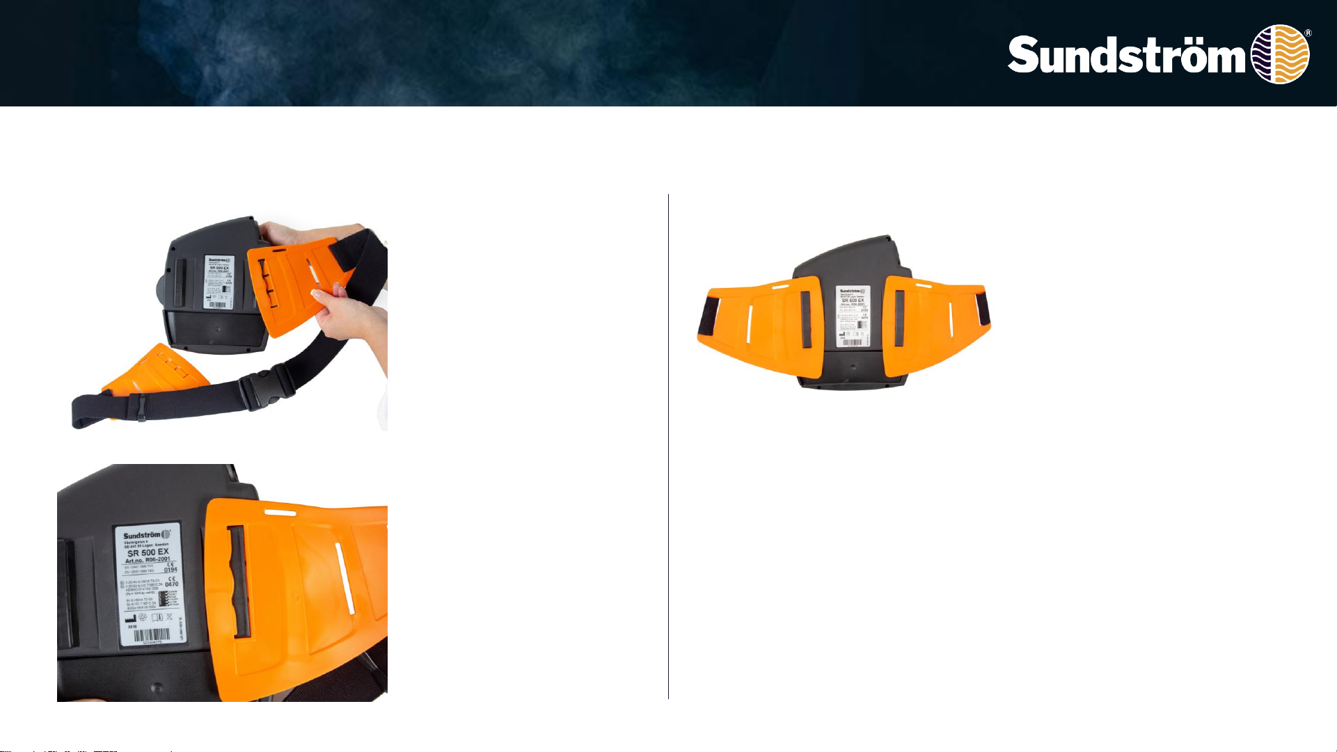
2.1 Check before use that the
gasket around the opening to
the battery terminals are
undamaged.
Any dirt on the battery gasket
is wiped off with a dry cloth.
Relubricate the gasket with
Vaseline to facilitate
mounting.
2.2 During long-term storage
a scheduled charging
procedure is recommended,
as follows:
• Store the battery at room
temperature.
• Repeat charging after 6 to 8
weeks as long as the storage
continues.

3. Assembly belt
2019-10-23
OI06H-2018 SR 500 EX 7
3.1 Place the fan upside
down. The belt should be
mounted so that the belt is
pointing upwards. Insert the
three tongues of the belt half
into the slot in the fan.
Begin to insert the upper
tongue and then turn the belt
into the fan.
3.2 Press down the three lips
locking the belt half.
3.3 Correctly mounted belt.

4. Particle filter
2019-10-23
OI06H-2018 SR 500 EX 8
4.1 Check that the gaskets in
the filter mounting of the fan
unit are in place and are in
good condition.
4.2 Snap the filter onto the
filter adapter.
4.3 Do not press onto the
centre of the filter –it might
damage the filter paper.
4.4 Screw the adapter into
the filter mounting so far that
the adapter will be in contact
with the gasket.
Then turn it about 1/8 turn
further in order to ensure a
good seal.

2019-10-23
OI06H-2018 SR 500 EX 9
4.5 Fit one pre-filter into the
filter holder.
The pre-filter should have
slipped under the shoulders
in the pre-filter holder.
Press the filter holder onto
the particle filter.
4.6 Correctly mounted pre-
filter holder with particle filter.

5. Combined filters, Gas filter + particle filter
2019-10-23
OI06H-2018 SR 500 EX 10
5.1 Snap the particle filter
onto the gas filter.
5.2 The arrows on the particle
filter must point towards the
gas filter.
Do not press onto the centre
of the filter it might damage
the filter paper.
5.3 Check that the gaskets in
the filter mounting of the fan
unit are in place and are in
good condition.

5. Combined filers, Gas filter + particle filter
2019-10-23
OI06H-2018 SR 500 EX 11
The filters used must be of the same type,
i.e. two SR 510 P3 or two SR 518 A2/SR510 P3, etc.
When filters are changed, both filters/combined filters must be
changed at the same time.
5.4 Fit one pre-filter, SR 221
into the filter holder.
Screw the filter combination
into the filter mounting so far
that the filter will be in contact
with the gasket. Then turn it
about 1/8 turn further in order
to ensure a good seal. Press
the filter holder onto the
particle filter.
5.5 Correctly mounted
pre-filter holder.

6. Operation/Performance
2019-10-23
OI06H-2018 SR 500 EX 12
6.1 Start the fan by pressing
the control button.
To switch of fan unit, keep the
control button depressed for
about two seconds.
6.2 After the button has been
pressed, a programmed test
will be run on the fan and the
display will then light up, the
audible signal will sound.
6.3 After the internal test, all
symbols will be extinguished
except the small green fan
symbol. This indicates normal
operating status with a flow of
at least 175 l / min.

Operation/Performance
2019-10-23
OI06H-2018 SR 500 EX 13
6.4 If the button is pressed
again, boosted operating
status will be activated, with a
flow at least 225 l/min. This is
indicated by the larger green
fan symbol lighting up.
To revert to normal operation,
press the control button once
again.
6.5 When about 5% of the
battery capacity is left, the fan
will begin to initiate an alarm
and the battery symbol will
flash. The battery capacity is
sufficient to allow the work to
be concluded without undue
haste. The work should then
be interrupted and the wearer
of the equipment should
leave the site

7. Performance check, minimum flow
2019-10-23
OI06H-2018 SR 500 EX 14
9.1 Check that the fan unit is
complete, correctly mounted,
thoroughly cleaned and
undamaged.
Connect the hose from the
head top to the fan unit and
turn it about 1/8 of a turn
clockwise.
9.2 Turn the flow meter bag
inside out and the flow meter
appears.
9.3 Place the head top in the
flow meter bag and start the
fan.
Grip the lower part of the bag
in order to seal around the
hose.
Grip around the measuring
tube and hold the tube
vertical.
The ball should now float
level with or just over the 175
l/min marking.
If the minimum flow is not
achieved, check that:
-The flow meter is vertical
-The ball moves freely
-The bag seals well around
the hose

8. Performance check, alarms
2019-10-23
OI06H-2018 SR 500 EX 15
The equipment is designed to provide a warning if the air flow is
obstructed, and this should be checked in conjunction with the
flow. Check before the equipment is taken into use.
N.B. If the minimum flow is not achieved or if the alarm signals
do not operate as intended, the fan must not be used.
10.1 Cause a flow stoppage
by still holding tightly the joint
between the hose and the
flow meter bag and then
blocking off the flow meter
outlet.
10.2 The fan will now initiate
an alarm by audible and
visual signals.
10.3 If the flow meter outlet is
now unblocked and the air is
allowed to flow freely, the
alarm signals will cease
within 10 –15 seconds.
Switch off the fan and remove
the head top from the flow
meter bag.

9. Putting the equipment on
2019-10-23
OI06H-2018 SR 500 EX 16
Before putting the equipment on, read carefully the user
instructions for the head top.
After the filter has been fitted, a performance check has been
carried out and the head top has been connected, the equipment
can be put on.
11.1 Snap the two ends of the
belt together.
After the buckles have been
connected, tighten the belt so
that it is comfortable.
11.2 The fan should be firmly
in contact with the wearer’s
back in order to ensure
optimum comfort and
ergonomic benefits.
11.3 Put the belt ends in the
clips on each side of the belt.

10. To change the particle filters
2019-10-23
OI06H-2018 SR 500 EX 17
12.1 Change particle filter by
bending the pre-filter holder
from the filter adapter.
Bear in mind that both filters
must be changed at the same
time.
12.2 Grip the filter with one
hand.
Place the thumb of the other
hand on the underside of the
adapter at the semicircular
gap. Then prise out the filter.
12.3 Change pre filter by
press it in the middle and
then remove it.

To change the gas filters, combined filters
2019-10-23
OI06H-2018 SR 500 EX 18
12.4 To change the gas filter:
Unscrew the filter/combined
filter. To change the gas filter,
prise the particle filter off the
gas filter.
12.5 As an alternative, the
filter combination can be
separated by means of the
filter adapter.
Both filters/combined filters must be changed at the same time
and must be of the same type and class.

11. Cleaning/Disinfection
2019-10-23
OI06H-2018 SR 500 EX 19
Wipe the outside of the fan.
If necessary, spray the product with 70 % ethanol or isopropanol
solution for disinfection.
13.1 The Plug kit is used for
cleaning or decontamination
of the fan unit and prevents
dirt and water from entering
the fan housing.
Disconnect the breathing
hose and the filters and install
the plugs.
13.2 In the event of heavy
fouling, a soft brush or
sponge wetted with a solution
of water and dishwashing
detergent can be used.
13.3 An SR 5226 cleaning
wipe should be used for daily
cleaning.

Cleaning/Disinfection
2019-10-23
OI06H-2018 SR 500 EX 20
13.4 Clean the gasket on the
battery.
N.B.! Check that the gasket
which is situated around the
contact plate opening
underneath the battery is
intact. If it´s not, change
battery..
13.5 Clean the pre-filter
holders inside and out.
13.6 Wipe the filter adapter
clean.
Check that the sealing ridge
for the particle filter is
undamaged.
13.7 Wipe the belt clean.
Other manuals for SR 500 EX
4
This manual suits for next models
2
Table of contents
Other Sundstrom Fan manuals