Sunex 9002B Product manual

9002B Rev. A : Parts Breakdown & Operating Manual
Fluid Nozzle .............................................. 1.4mm
Air Consumption.................................. 14.5 CFM
Fluid (Water) Delivery .............. 160-220 ML/MIN
Air Pressure .............................................. 43 PSI
Cup Size...................................................600 ML
Air Inlet.................................................. 1/4" NPT
9002B Rev. A
Gravity Feed HvLP
SPray Gun witH
reGuLator /
PreSSure GauGe
SPECIFICATIONS
ALWAYS READ AND KEEP
INSTRUCTIONS BEFORE
USING THIS EQUIPMENT
SPRAY GUNS CREATE
FLYING PARTICLES.
ALWAYS WEAR SAFETY
GOGGLES AND BREATHING
APPARATUS (USERS AND
BYSTANDERS). FLYING
PARTICLES CAN CAUSE
INJURY
WARNING
Operating Instructions • Warning Information • Parts Break down

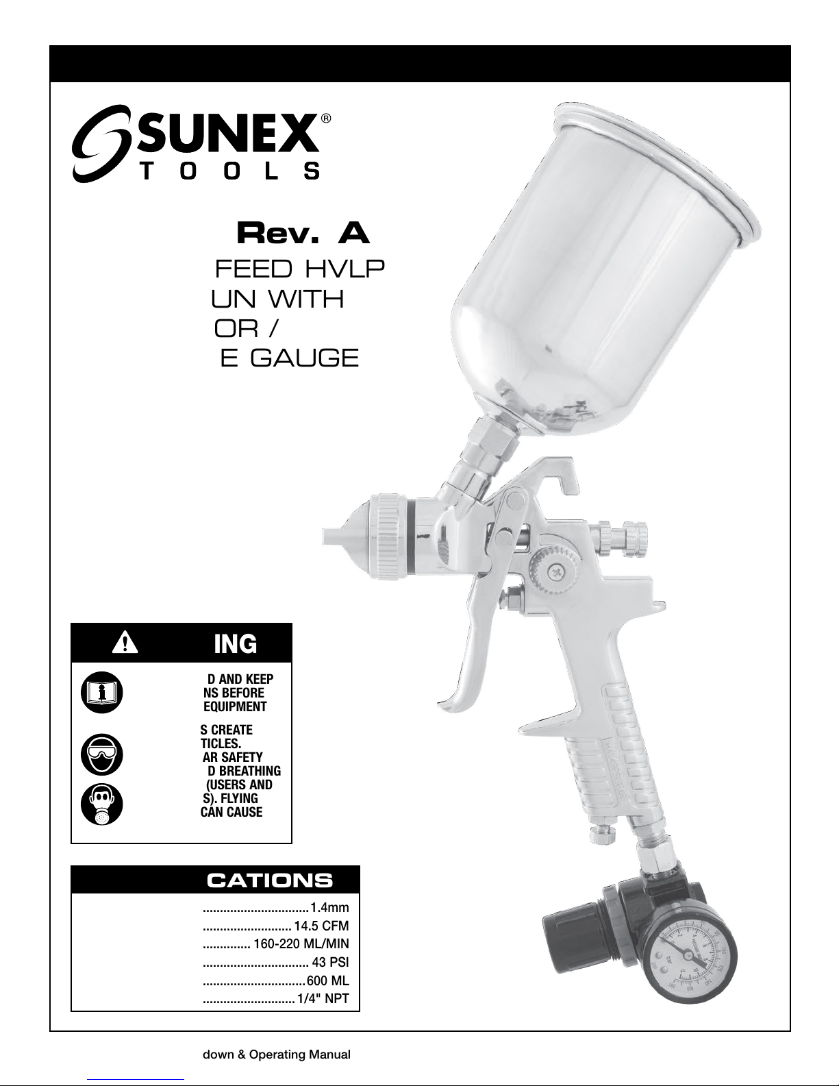
9002B Rev. A : Parts Breakdown & Operating Manual 2 03/07/13
To reduce the risk of injury, anyone using, repairing, maintaining, or changing accessories on this tool must
read and understand these instructions before performing any of these tasks.
WARNING
Read THIS INSTRUCTION MANUAL Carefully and understand ALL
INFORMATION Before Operating THIS Tool. KEEP FOR FUTURE USE.
Always operate, inspect and maintain this spray gun in
accordance with American National Standards Institute Safety
Code of Portable Air Tools (ANSI B186.1) and any other applicable
safety codes and regulations.
During use and while cleaning and flushing spray gun solvents
can be expelled. Some solvents can cause eye injury. Always
wear eye protection.
Be sure all in the area are wearing impact-resistant eye and
face protection.
Even small projectiles can injure eyes and cause blindness.
High sound levels can cause permanent hearing loss. Protect
yourself from noise. Noise levels vary with work surface. Wear
ear protection.
Repetitive work motions, awkward positions and exposure to
vibration can be harmful to hands and arms.
Air under pressure can cause severe injury. Always shut off air
supply, drain hose of air pressure and disconnect tool from air
supply when not in use, before changing accessories or when
making repairs. Never direct air at yourself or anyone else.
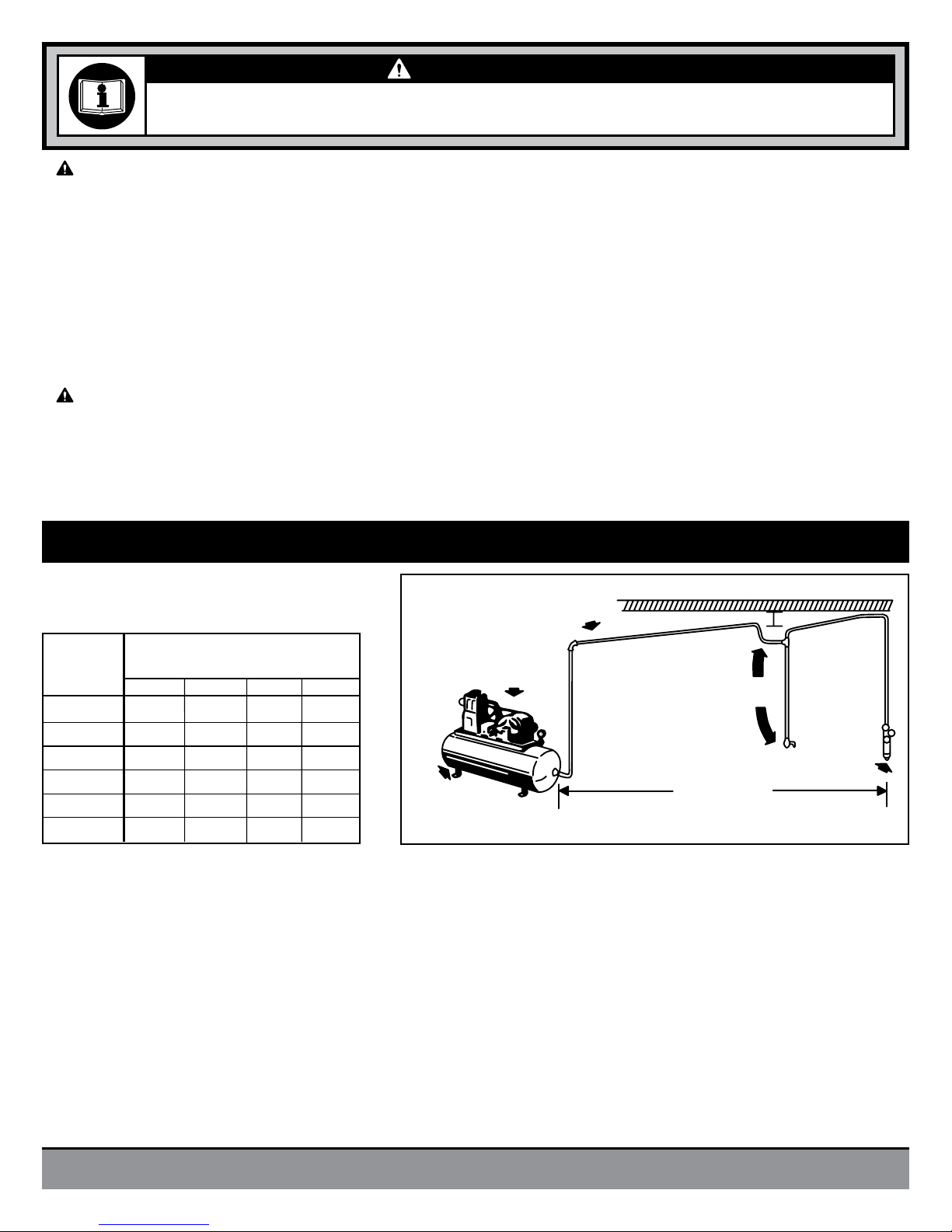
Whipping hoses can cause serious injury. Always check for
damaged or loose hoses and fittings. Never use quick change
couplings at tool. They add weight and could fail due to vibration.
Instead, add a whip hose and connect coupling between air
supply and whip hose, or between whip hose and leader hose.
Do not exceed maximum air inlet pressure of 43 PSI.
Always use spray gun at a safe distance from other people in
work area.
Maintain spray gun with care. Keep tools clean and oiled for
best and safest performance. Follow instructions for lubricating
and changing accessories. Wiping or cleaning rags and other
flammable waste materials must be placed in a tightly closed
metal container and disposed of later in the proper fashion.
Do not wear loose or ill-fitting clothing; remove watches and rings.
Do not over reach. Keep proper footing and balance at all times.
Slipping, tripping and falling can be a major cause of serious
injury or death. Be aware of excess hose left on the walking or
work surface.
Do not abuse hoses or connectors. Never carry spray gun by the
hose or yank hose to disconnect from air supply. Keep hoses from
heat, oil and sharp edges. Check hoses for weak or worn condition
before each use, making certain that all connections are secure.
When possible, secure work with clamps or vise so both hands
are free to operate tool.
Solvent and paint coatings can be highly flammable when
sprayed. Adequate ventilation exhaust must be provided to keep
air free of accumulations of flammable materials. Smoking must
never be allowed in the spray area. Fire extinguishing equipment
must be present in the paint spray area.
Certain painting solvent materials may be harmful if inhaled, or if
there is contact with the skin. Always follow the requirements of
the Material Safety Data Sheet supplied by your coating material
manufacturer. Adequate exhaust ventilation must be provided to
keep the air free of accumulations of toxic materials. Always use a
mask or respirator whenever there is a chance of inhaling sprayed
materials. The mask must be compatible with the material being
sprayed and its concentration. Respirator equipment must be
NIOSH approved.
Halogenated hydrocarbon solvents - for example: methylene
chloride and 1,1,1,-Trichlorethene are not chemically compatible
with the aluminum that might be used in spray gun components.
The chemical reaction caused by these solvents reacting with
aluminum can become violent and lead to an equipment
explosion. Guns with stainless steel internal passageways may
be used with these solvents. However, aluminum is widely used
in other spray application equipment. Check all equipment items
before use and make sure they can also be used safely with these
solvents. Read the label or data sheet for the material you intend
to spray. If in doubt as to whether or not a coating or cleaning
material is compatible, contact your material supplier.
Spray gun operators should be given adequate training in the
safe use and maintenance of the equipment. Users must comply
with all local and national codes of practice and insurance
company requirements governing ventilation, fire precautions,
operation, maintenance, and housekeeping. These are OSHA
Sections 1910.94 and 1910.107 and NFPA-33.
Use of spray guns may cause cumulative trauma disorders
(CTD's). CTD's, when using spray guns, tend to affect the upper
extremities. Factors which may increase the risk of developing a
CTD include:
1. High frequency of the activity.
2. Excessive force, such as gripping, pinching, or pressing
with the hands and fingers.
3. Extreme or awkward finger, wrist, or arm positions.
4. Excessive duration of the activity.
5. Vibration.
6. Repeated pressure on a body part.
7. Working in cold temperatures.
CTD's can also be caused by sports activities. Pain, tingling, or
numbness in the shoulder, forearm, wrist, hands, or fingers,
especially during the night, may be early symptoms of a CTD.
Do not ignore them. Should you experience any such symptoms,
see a physician immediately. Other early symptoms may include
vague discomfort in the hand, loss of manual dexterity, and
nonspecific pain in the arm. Ignoring early symptoms and
continued repetitive use of
the arm, wrist, and hand can lead
to a serious disability.
SAFETY INSTRUCTIONS - DO NOT DISCARD - GIVE TO USER

9002B Rev. A : Parts Breakdown & Operating Manual 3 03/07/13
To reduce the risk of injury, anyone using, repairing, maintaining, or changing accessories on this tool must
read and understand these instructions before performing any of these tasks.
WARNING
SAFETY INSTRUCTIONS - DO NOT DISCARD - GIVE TO USER
(CONTINUED)
AIR SUPPLY
Never mount oil and water extractor on or near the air compressor.
During compression, air temperature is greatly increased. As the air cools down to room temperature, moisture condenses in the air line, on
its way to the spray gun. Therefore, always mount the oil and water extractor at a point in the air supply system where the compressed air
temperature is lowest.
Drain air lines properly.
Pitch all air lines back towards the compressor so that condensed moisture will flow back into the air receiver where it can be drained off.
Each low point in an air line acts as a water trap. Such points should be fitted with an easily accessible drain. See diagram above.
Length of Pipe (ft.)
Air
Flow
CFM 50 100 150 200
10
20
30
40
50
70
1/2"
3/4"
3/4"
1"
1"
1"
3/4"
3/4"
3/4"
1"
1"
1"
3/4"
3/4"
1"
1"
1"
1-1/4"
3/4"
3/4"
1"
1"
1"
1-1/4"
Oil & Water
Extractor
Drain
Oil and Water Extractor should be at least 25 ft.
from the compressor, farther if possible.
25 Feet
or More
Install drain at
each low point
Compressor Unit
Pitch pipe back
toward air receiver
Drain
Some dust created by power sanding, sawing, grinding, drilling
and other construction activities contains chemicals known to
the State of California to cause cancer and birth defects or other
reproductive harm. Some examples of these chemicals are:
- Lead from lead based paints
- Crystalline silica bricks and cement and other
masonry products
- Arsenic and chromium from chemically-treated lumber
Your risk from these exposures varies, depending on how often
you do this type of work. To reduce your exposure to these
chemicals: work in a well ventilated area, and work with approved
safety equipment, such as those dust masks that are specially
designed to filter out microscopic particles.
Handling the brass parts of this product will expose you to lead, a
chemical known to the State of California to cause birth defects
and other reproductive harm. Wash hands after handling.
IMPORTANT PRECAUTION INFORMATION -
READ BEFORE USING THIS SPRAY GUN:
SPRAY GUN DESCRIPTION
The 9002B Rev. A is a light weight, anodized aluminum, general
purpose gravity feed spray gun designed for use in various types
of spraying applications. The 9002B Rev. A can handle water
based and solvent based spraying applications.
IMPORTANT: This spray gun may be used with most common
coating and finishing materials. It is designed for use with mildly
corrosive and non-abrasive materials. If used with other high
corrosive or abrasive materials, it must be expected that frequent
and thorough cleaning will be required and the necessity for
replacement of parts will be increased..
For maximum transfer efficiency, do not use more pressure than
is necessary to atomize the material being applied.
Connect the gun to a clean, moisture and oil free air supply using
a hose size of at least 5/16" I.D. hose. Do not use 1/4" I.D. hose.
(25' x 1/4" hose at 18 cfm has a pressure loss of 25 psi. 25' x
5/16" hose at 18 cfm has a pressure loss of 8 psi.)

9002B Rev. A : Parts Breakdown & Operating Manual 4 03/07/13
GRAVITY FEED HOOKUP
Air pressure for atomization is regulated at extractor.
Amount of fluid is adjusted by fluid control screw on
gun, viscosity of paint, and air pressure.
INSTALLATION
This spray gun is rugged in construction, and is built to
yield exceptional value. The life of this product and the
efficiency of its operation depend upon a knowledge of
its construction, use and maintenance.
FOR BEST PERFORMANCE, PLEASE BE SURE TO DO THE FOLLOWING
BEFORE USING THIS SPRAY GUN
• Tightentheguntothecupsecurelywiththenutandfittingsupplied.
• Besuretohavetheproperairpressureattheguntooperate.Properairpressureforthistoolshouldnotexceed50PSI
• Adjustfluidcontrolscrewandspraywidthadjustmentscrewtoyourdesiredpatternbeforeusingonproduction.
• Cleanallpartsafteruse.
In normal use, the nozzle wings are horizontal as shown here. This provides a vertical fan-shaped pattern which
gives maximum, even material coverage as the gun is moved back and forth parallel to the surface being finished.
Spray pattern may be infinitely adjusted
from round to flat.
Set inlet pressure at no more than 50 PSI. For optimum performance,
some materials may spray better at PSI ratings below 50 PSI. If unsure,
always test at PSI ratings before using on final production. Try spray.
If it is too fine, decrease the air pressure or open fluid control screw. If
the spray is too thick, close the fluid control screw. Regulate the pattern
width and repeat adjustment of spray as needed.
®
®
®
Air flow adjustment screw
Turn right to decrease flow, left to increase
ADJUSTMENTS
SPRAYING
Gravity Feed
Cup
Air Inlet
Air Hose
Atomization
Pressure
Gauge
Oil and
Water
Extractor
Air Flow
Adjustment
Screw
Fluid Control Screw
Spray Width
Adjustment Screw
Spray width adjustment screw
Turn right for round, left for fan.
Fluid control screw
Turn right to decrease flow, left to increase.

9002B Rev. A : Parts Breakdown & Operating Manual 5 03/07/13
OPERATION
Proper handling of the gun is essential for obtaining a good finish. The gun should be held at a right angle to the surface being covered, and moved
parallel with it. For precise control of the gun and material, the trigger should be released before the end of the stroke.
Hold the gun from 6 to 12 inches away from the surface depending on material and atomizing pressure. For a uniform finish, lap each stroke over the
preceding stroke, making sure the spray is smooth and wet.
Light Coat Heavy Coat
WRONG
Start
stroke Pull
trigger Release
trigger End of
Stroke
RIGHT
Even and wet coat
6 to 12 inches
SPRAY GUN
1. Submerge the front end of the gun in solvent just until the fluid connection is covered.
2. Paint that has built up on the gun should be removed using a bristle brush and solvent.
3. Never submerge all of the spray gun in solvent because:
• Thiswilldissolvethelubricantinthepackingsandonwearsurfaces,causing
them to dry out and resulting in difficult operation and faster wear.
• Airpassagesinthegunwillbecomecloggedwithdirtysolvent.
4. Using a rag moistened with solvent, wipe down the outside of the gun.
5. Oil gun daily. Use a drop of lightweight machine oil on:
A. fluid needle packing
B. air valve packing
C. trigger pivot point
See Fig. 1 for Location of Above Points.
6. NOTE: Do not soak rubber o-rings or seals in paint thinner. O-rings and seals
can be wiped clean with paint thinner but soaking can cause these items to
deteriorate over time.
7. Caution: Do not use lubricants which contain silicone.
Silicone may cause defects in the finish application.
CAUTION…
To avoid cross-threading, all spray gun parts should be screwed in hand tight initially. If the parts can not easily be turned by hand, be sure you have
the correct parts, unscrew, realign, and try again. NEVER use excessive force in matching parts.
AIR NOZZLE, FLUID NOZZLE, AIR VALVE ASSEMBLY
1. All nozzles and needles are made to exact standards. They should be handled carefully.
2. To clean nozzles, immerse them in solvent until any dried material is dissolved, then blow them clean.
3. Do not use metal or sharp instrument to probe any of the holes in the nozzles.
4. Air flow should occur before fluid-flow when the gun is triggered. It may be necessary to adjust the fluid control screw to make sure air flows
before fluid.
5. Do not alter the gun in any way.
GRAVITY FEED
Turn off air supply. Remove cover of cup. Empty the cup of material. Clean the cup and cover. Turn on air supply and spray with proper cleaning
solvent. Repeat with clean solvent if necessary. Remove solvent, disconnect gun, remove air cap and clean. Wipe gun and cup with rag
dampened with solvent.
C
A
B
FIG. 1
CLEANING AND MAINTENANCE

9002B Rev. A : Parts Breakdown & Operating Manual 6 03/07/13
One side of nozzle wing is clogged.
PROBLEMSPRAY PATTERN/
CONDITION
A.) Loose air nozzle.
B.) Material around outside of
air nozzle has dried.
A.) Atomization air pressure is set
too high.
B.) Trying to spray a thin material
in too wide a pattern.
Spitting
SOLUTION
A.) Reduce air pressure.
B.) Increase material control by turning fluid
control screw to left, while reducing spray
width by turning spray width adjustment
screw to right.
Soak nozzle in solvent to loosen clog, then blow air through
until clean. To clean orifices use a broom straw or toothpick.
Never try and detach dried material with sharp tool.
A.) Tighten air nozzle.
B.) Take off air nozzle and wipe off fluid tip,
using rag moistened with thinner.
A.) Back up knurled nut, put a few drops of
machine oil on packing, re-tighten nut.
B.) Take off fluid nozzle, clean rear of nozzle and
seat in gun body. Replace nozzle and bring in
tight to body.
C.) Tighten or change out swivel nut.
A.) Packing around needle valve
is dried out.
B. Fluid nozzle loosely installed,
or dirt between nozzle
and body.
C.) Loose or defective swivel nut
on siphon cup.
Fluid leakage from
packing nut.
A.) Packing nut loose.
B.) Packing worn or dry.
A.) Tighten, but not so tight as to grip needle.
B.) Replace packing or lubricate.
Dripping from fluid tip.
A.) Dry packing.
B.) Sluggish needle.
C.) Tight packing nut.
D.) Worn fluid nozzle or needle.
A.) Lubricate.
B.) Lubricate.
C.) Adjust.
D.) For pressure feed, replace with new fluid nozzle
and needle.
Thin, sandy coarse finish.
Thick, dimpled finish
resembling orange peel.
A.) Gun held too far from surface.
B.) Atomization pressure set
too high.
Gun held too close to surface.
A.) Move gun closer to surface.
B.) Adjust atomization pressure.
Move gun further from surface.
Will not spray.
A.) No air pressure at gun.
B.) Fluid pressure too low with
internal mix cap and
pressure tank.
C.) Fluid control screw not
open enough.
D.) Fluid too heavy.
A.) Check air supply and air lines.
B.) Increase fluid pressure at tank.
C.) Open fluid control screw.
D.) Thin material or change to pressure feed.
Unable to get round spray. Fan adjustment screw not
seating properly.
Clean or replace.
Improper spray pattern.
A.) Gun improperly adjusted.
B.) Dirty air cap.
C.) Fluid tip obstructed.
D.) Sluggish needle.
A.) Readjust gun. Follow instructions carefully.
B.) Clean air cap.
C.) Clean.
D.) Lubricate.
TROUBLESHOOTING

9002B Rev. A : Parts Breakdown & Operating Manual 7 03/07/13
REF. DESCRIPTION QTY.
NO.
1 Gun Body 1
2 Gasket 4
3 Sealing Screw 1
4 Airflow Separating Ring 1
5 Nozzle Seat Gasket 1
6 Nozzle Seat 1
7 Material Nozzle 1
8 Air Nozzle Circlip 1
9 Air Nozzle 1
10 Air Nozzle Gasket 1
11 Air Cap 1
12 Air Valve Spring 1
13 Air Valve Stem 1
14 Sealing Gasket 1
15 Air Valve Body 1
16 Sealing Nut 1
17 Air Flow Adustment Stem 1
18 Gasket 2
REF. DESCRIPTION QTY.
NO.
19 Air Flow Adjustment Spring 1
20 O-Ring 2.5 x 1.8 1
21 Air Flow Adjustment Seat 1
22 Air Flow Adjustment Knob 1
23 Air Joint 1
24 Opening Stopper 1
25 O-Ring 5.3 x 1.5 1
26 Pattern Adjustment Seat 1
27 O-Ring 6 x 1.8 1
28 Pattern Adjustment Stem 1
29 Pattern Adjustment Knob 1
30 Cross Recess Nut 1
31 Opening Stopper 4 2
32 Trigger 1
33 Trigger Pin 1
34 Flexible Pin 1
35 Needle 1
36 Needle Adj. Spring 1
REF. DESCRIPTION QTY.
NO.
37 Needle Adjustment Seat 1
38 Needle Adjustment Knob 1
39 Material Passage Connector 1
40 Filter 1
41 Sealing Gasket 1
42 Fluid Connector 1
43 Gasket 1
44 Cup 1
45 Screw 1
46 Cup Cover 1
47 Hex Wrench 1
48 Hex Connector Nut 1
49 Connector 1
50 Brush 1
51 Spanner Wrench 1
52 Regulator 1
Only items identified by part numbers are available separately.
Parts Available:
9091: Regulator (Item #52)
Replacement Parts Available:
RS9002BRK: Repair Kit (incl. #2, 5, 13-15, 18, 20, 25, 27, 41)
RS9002BNK: Air Nozzle/Fluid Nozzle/Needle Kit (incl. #8-11, 35, 36)
RS9002BF: Filter (set of 5) #40
RS9002BSW: Spray Width Assy. incl. #26, 28-30)
RS9002BAF: Air Flow Assy. (incl. #17-22)
Shop for other air tools & compressors on our website.
Table of contents
Other Sunex Paint Sprayer manuals