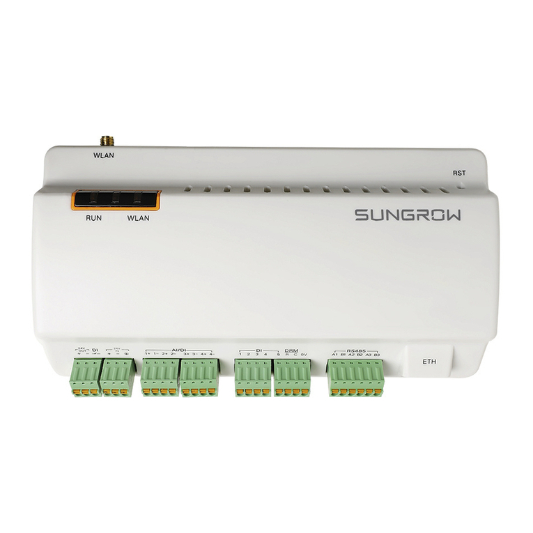
Sungrow Logger1000B User manual

Logger1000A/
Logger1000BData LoggerUser
ManualLogger1000A_B-UEN-Ver19-
202211 M-H-001405
User Manual
Data Logger
Logger1000A/Logger1000B
Logger1000A_B-UEN-Ver19-202211


I
All Rights Reserved
All Rights Reserved
No part of this document can be reproduced in any form or by any means without the prior
written permission of Sungrow Power Supply Co., Ltd (hereinafter "SUNGROW").
Trademarks
and other Sungrow trademarks used in this manual are owned by
SUNGROW.
All other trademarks or registered trademarks mentioned in this manual are owned by their
respective owners.
Software Licenses
• It is prohibited to use data contained in firmware or software developed by SUNGROW,
in part or in full, for commercial purposes by any means.
• It is prohibited to perform reverse engineering, cracking, or any other operations that
compromise the original program design of the software developed by SUNGROW.

II
About This Manual
The manual mainly contains the product information, as well as guidelines for installation,
operation, and maintenance. The manual does not include complete information about the
photovoltaic (PV) system. Readers can get additional information at www.sungrowpower.
com or on the webpage of the respective component manufacturer.
Validity
This manual is valid for the following models:
• Logger1000A(4G version)
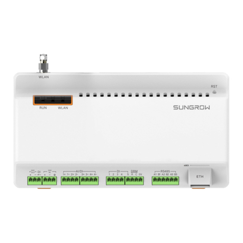
• Logger1000B(non-4G version)
The foregoing Loggers are referred to as the "Logger1000" for short unless otherwise
specified.
Target Group
This manual is intended for professional technicians who are responsible for installation,
operation, and maintenance of inverters, and users who need to check inverter parameters.
The product must only be installed by professional technicians. The professional technician
is required to meet the following requirements:
• Know electronic, electrical wiring and mechanical expertise, and be familiar with
electrical and mechanical schematics.
• Have received professional training related to the installation and commissioning of
electrical equipment.
• Be able to quickly respond to hazards or emergencies that occur during installation and
commissioning.
• Be familiar with local standards and relevant safety regulations of electrical systems.
• Read this manual thoroughly and understand the safety instructions related to
operations.
How to Use This Manual
Please read this manual carefully before using the product and keep it properly at a place
for easy access.
All contents, pictures, marks, and symbols in this manual are owned by SUNGROW. No part
of this document may be reprinted by the non-internal staff of SUNGROW without written
authorization.
Contents of this manual may be periodically updated or revised, and the actual product
purchased shall prevail. Users can obtain the latest manual from support.sungrowpower.
com or sales channels.

III
Symbols
This manual contains important safety instructions, which are highlighted with the following
symbols, to ensure personal and property safety during usage, or to help optimize the
product performance in an efficient way.
Please carefully understand the meaning of these warning symbols to better use the manual.
Indicates high-risk potential hazards that, if not avoided, may lead to death or
serious injury.
Indicates moderate-risk potential hazards that, if not avoided, may lead to death or
serious injury.
Indicates low-risk potential hazards that, if not avoided, may lead to minor or
moderate injury.
Indicates potential risks that, if not avoided, may lead to device malfunctions or
financial losses.
“NOTE” indicates additional information, emphasized contents or tips that may be
helpful, e.g., to help you solve problems or save time.


V
Contents
All Rights Reserved .....................................................................................................I
About This Manual......................................................................................................II
1 Safety Instructions ............................................................................................1
1.1 Unpacking and Inspection ...............................................................................2
1.2 Installation Safety ...........................................................................................2
1.3 Electrical Connection Safety............................................................................2
1.4 Operation Safety ............................................................................................3
1.5 Maintenance Safety........................................................................................3
1.6 Disposal Safety ..............................................................................................4
2 Product Description ..........................................................................................5
2.1 Function Introduction ......................................................................................5
2.2 Performance Features ....................................................................................5
2.3 Networking Application ...................................................................................5
2.4 Product Introduction........................................................................................7
3 Unpacking and Storage ...................................................................................9
3.1 Scope of Delivery ...........................................................................................9
3.2 Identifying the Logger1000 ............................................................................10
3.3 Checking upon Receiving..............................................................................10
3.4 Storage........................................................................................................10
4 Mechanical Mounting .....................................................................................12
4.1 Installation Location Selection .......................................................................12
4.2 Installation Tools...........................................................................................13
4.3 Installation Method .......................................................................................13
4.3.1 Wall-Mounted Installation.....................................................................13
4.3.2 Guide Rail-Mounted Installation............................................................15
4.4 Installing Antenna.........................................................................................16
4.5 Installing Power Box .....................................................................................17
5 Electrical Connection .....................................................................................19
5.1 Safety Instructions........................................................................................19
5.2 Port Introduction...........................................................................................19
5.3 Connection to PV Devices.............................................................................20

VI
5.3.1 Connection to a single inverter .............................................................20
5.3.2 Connection to multiple devices.............................................................23
5.3.3 Connection to Smart Energy Meter.......................................................23
5.3.4 Connection to Meteo Station ................................................................25
5.4 Connection to Background ............................................................................26
5.5 Connection to Micro-SIM...............................................................................27
5.6 Connection to Power Box ..............................................................................27
5.7 Cable Routing Requirements.........................................................................29
6 Commissioning ...............................................................................................30
6.1 Inspection before Commissioning ..................................................................30
6.2 Commissioning Steps ...................................................................................30
7 WEB Interface .................................................................................................33
7.1 Running Requirements .................................................................................33
7.2 Login Steps..................................................................................................33
7.2.1 WLAN Login .......................................................................................33
7.2.2 Ethernet Login ....................................................................................34
7.3 Web Main Interface.......................................................................................34
7.4 Web Menu ...................................................................................................35
7.5 Operation Procedure ....................................................................................36
7.6 Overview .....................................................................................................37
7.6.1 General Information ............................................................................37
7.6.2 Current Alarms....................................................................................37
7.7 Device Monitoring.........................................................................................38
7.7.1 RealTime Values.................................................................................38
7.7.2 DC Data .............................................................................................38
7.7.3 Initial Parameter..................................................................................38
7.7.4 Protection Parameter ..........................................................................39
7.7.5 General Parameter..............................................................................39
7.7.6 Device Instruction ...............................................................................39
7.7.7 Device Information ..............................................................................40
7.8 Device Maintenance .....................................................................................40
7.8.1 Device List..........................................................................................40
7.8.2 Firmware Update ................................................................................45
7.8.3 Inverter Log ........................................................................................45
7.8.4 AFCI Activation...................................................................................46
7.9 History Data .................................................................................................46

VII
7.10 System ......................................................................................................46
7.10.1 Running Information ..........................................................................46
7.10.2 System Maintenance.........................................................................46
7.10.3 Remote Maintenance ........................................................................47
7.10.4 Message Export ................................................................................48
7.10.5 System Time.....................................................................................49
7.10.6 iSolarCloud.......................................................................................50
7.10.7 IEC104.............................................................................................50
7.10.8 MODBUS .........................................................................................54
7.10.9 Third-party portal...............................................................................55
7.10.10 Port Parameter................................................................................55
7.10.11 MPLC .............................................................................................59
7.10.12 About .............................................................................................59
8 Grid Dispatching Function .............................................................................60
8.1 Function Description .....................................................................................60
8.2 Interface Description.....................................................................................61
8.2.1 Digital Control Interface .......................................................................61
8.2.2 Analog Control Interface ......................................................................62
8.2.3 DRM Control Interface.........................................................................63
8.3 Power Control ..............................................................................................63
8.3.1 Active Power ......................................................................................63
8.3.2 Reactive Power...................................................................................70
8.3.3 Emergency Button ..............................................................................76
9 Device Maintenance ......................................................................................77
9.1 Safety Instructions........................................................................................77
9.2 Maintenance ................................................................................................77
9.3 Troubleshooting ...........................................................................................78
10 Appendix .......................................................................................................81
10.1 Technical Data............................................................................................81
10.2 Dry Contact Wiring Cable ............................................................................82
10.3 Quality Assurance ......................................................................................82
10.4 Contact Information ....................................................................................83


1
1Safety Instructions
When installing, commissioning, operating, and maintaining the product, strictly observe the
labels on the product and the safety requirements in the manual. Incorrect operation or work
may cause:
• Injury or death to the operator or a third party.
• Damage to the product and other properties.
• Do not operate the product and cables (including but not limited to moving the
product, installing the product, operating the product and cables, powering up
the product, maintaining the product, and working at heights) in harsh weather
conditions such as lightning, rain, snow, and level 6 or stronger wind.
• In case of fire, evacuate from the building or product area and call the fire alarm.
Re-entry into the burning area is strictly prohibited under any circumstances.
• Tighten the screws with the specified torque using tools when fastening the
product and terminals. Otherwise, the product may be damaged. And the
damage caused is not covered by the warranty.
• Learn how to use tools correctly before using them to avoid hurting people or
damaging the device.
• Maintain the device with sufficient knowledge of this manual and use proper
tools.
• The safety instructions in this manual are only supplements and cannot cover
all the precautions that should be followed. Perform operations considering
actual onsite conditions.
• SUNGROW shall not be held liable for any damage caused by violation of
general safety operation requirements, general safety standards, or any safety
instruction in this manual.
• When installing, operating, and maintaining the product, comply with local
laws and regulations. The safety precautions in this manual are only
supplements to local laws and regulations.

2
1.1 Unpacking and Inspection
• Check all safety signs, warning labels and nameplates on devices.
• The safety signs, warning labels and nameplates must be clearly visible and
cannot be removed or covered before the device is decommissioned.
After receiving the product, check whether the appearance and structural parts of
the device are damaged, and check whether the packing list is consistent with the
actual ordered product. If there are problems with the above inspection items, do
not install the device and contact your distributor first. If the problem persists,
contact SUNGROW in time.
1.2 Installation Safety
Make sure there is no electrical connection before installation.
Make sure to avoid the water and electricity wiring in the wall before drilling.
Improper installation may cause personal injury!
• When moving the product, be aware of the product weight and keep the balance
to prevent it from tilting or falling.
Before operating the product, please check and ensure that tools to be used have
been maintained regularly.
1.3 Electrical Connection Safety
Before electrical connections, please make sure that the product is not damaged.
Otherwise, it may cause danger!
Before electrical connections, please make sure that the product switch and all
switches connected to the product are set to "OFF", otherwise electric shock may
occur!
1 Safety Instructions User Manual

3
• Be sure to use special insulation tools during cable connections.
• Note and observe the warning labels on the product, and perform operations
strictly following the safety instructions.
• Respect all safety precautions listed in this manual and other pertinent
documents.
Damage to the product caused by incorrect wiring is not covered by the warranty.
• Electrical connection must be performed by professionals.
• Check the power cord and confirm that the identifier is correct before
connecting it.
• All cables used shall comply with the requirements of local laws and
regulations, and must be firmly attached, properly insulated, and adequately
dimensioned.
Comply with the regulations related to the local grid during wiring.
1.4 Operation Safety
• When the product is running, do not touch its enclosure.
• When the product is running, do not touch any wiring terminal of the product.
Otherwise, electric shock may occur.
• When the product is running, do not disassemble any parts of the product.
Otherwise, electric shock may occur.
1.5 Maintenance Safety
Unauthorized modification or use of parts not sold or recommended by SUNGROW
may result in fires and electric shocks.
User Manual 1 Safety Instructions

4
To prevent misuse or accidents caused by unrelated personnel, post prominent
warning signs or demarcate safety warning areas around the product to prevent
accidents caused by misoperation.
• To avoid the risk of electric shock, do not perform any other maintenance
operations beyond this manual. If necessary, contact SUNGROW for
maintenance. Otherwise, the losses caused are not covered by the warranty.
• If a fault occurs, only restart the device after the fault is cleared. Otherwise, the
fault may expand, and the device may be damaged.
1.6 Disposal Safety
Please scrap the product in accordance with relevant local regulations and
standards to avoid property losses or casualties.
1 Safety Instructions User Manual

5
2Product Description
2.1 Function Introduction
The Logger1000 is a device used for data collection, power control, and protocol conversion
for inverters and other PV equipment in the PV plant. The device is also integrated with
communication gateway and plant O&M function.
The Logger1000 is featured as flexible networking, auxiliary maintenance, and easy
operation.
2.2 Performance Features
Flexible networking
• Support of RS485, Ethernet, and WLAN communication
• Support of data collection from various environment sensors, Smart Energy Meters,
Meteo Stations, inverters, and other equipment
Auxiliary maintenance
• Support of batch inverter parameter setting and software upgrading
• Support of remote desktop function, lower maintenance costs
• Support of grid control instruction and power factor control
• Support of local real-time monitoring, unnecessary to connect the Internet
Easy operation
• Auto search and allocation of inverter address
• Embedded web operation interface, support of mobile phone access, free download of
the App
2.3 Networking Application
As shown in the figure below, the Logger1000 can be connected to iSolarCloud via an
ethernet switch.

7
• The Logger1000 supports various communication manners such as WLAN and 4G.
• The Logger1000 can be connected to various environment sensors, Smart Energy
Meters, Meteo Stations, and inverters in the PV power generation system via an RS485
bus.
• Users can access the Web interface via mobile phone or PC, on which parameter
configuration and remote on-line upgrading can be performed.
• The Logger1000 can transmit data to iSolarCloud and forward background instructions
to downstream devices.
• The Logger1000 is equipped with grid dispatching function, including active power
control, reactive power regulation, etc.
2.4 Product Introduction
Appearance
figure 2-1 Appearance
Item Designation Description
A Indicator Indicate the running state of the
Logger1000
B Vent -
CWLAN antenna mounting hole -
D* 4G antenna mounting hole -
EWiring terminal Refer to "table 5-1 Port description"
Note: D* is 4G antenna mounting hole. The Logger1000A is provided with the hole while the
Logger1000B is not. Specifically, refer to the actual product received. In the following,
description is given by using the Logger1000A as an example.
User Manual 2 Product Description

8
Indicator
Indicator
(print) LED color LED status Description
Running
indicator (RUN) Red/green
Off No external power supply
connected
Slow flash (Green) Normal running
Slow flash (Red) Device alarm
Steady on (Red) Logger1000 running fault
4G indicator
(4G) * Blue
Off No data communication
Steady on 4G connected successfully
Slow flash Data communication in
process
WLAN indicator
(WLAN) Blue
Off No data communication
Steady on WLAN connected
successfully
Slow flash Data communication in
process
Note: * Only the Logger1000A is equipped with the 4G indicator.
• Slow flash means that the indicator flashes once every second.
• Slow flash of the communication indicator indicates data communication in process. If
there has been no data communication with iSolarCloud for 10s, the indicator will keep
steady on.
Dimensions
figure 2-2 Dimensions
Width (W) Height (H) Depth (D)
200mm 110mm 60mm
2 Product Description User Manual

9
3Unpacking and Storage
3.1 Scope of Delivery
Check the scope of delivery for completeness according to the packing list. The following
items should be included.
figure 3-1 Scope of delivery
Item Designation Description
ALogger1000 Logger1000
B Documents Quick User Manual, quality certificate, packing list,
product test report, and warranty card
CCommunication
terminal resistor
6x120Ω (Note: if there are more than 15 devices
connected on the RS485 bus, it is recommended
to connect a 120Ω terminal resistor in parallel on
the A and B lines at the head or tail end of the bus)
DNylon cable tie Used to tie cables
EFastener assembly 4 sets, M4X16, used for wall-mounting to fasten
the device on the metal surface
FExpansion bolt 4 sets, ST4.8X19, used for wall-mounting to fasten
the device on the concrete wall
G Terminal fastener 2 sets, E/UK-1201442, fixed on the guide rail to
prevent the Logger1000 from moving
H Guide rail Length: 240mm
I
WLAN antenna
4G antenna
The Logger1000A is provided with the 4G antenna
mounting hole while Logger1000B is not.
Specifically, refer to the actual product received.
J Power box Converters the AC current into DC current Length
of supporting guide rail: 170mm

10
3.2 Identifying the Logger1000
The type and key technical parameters of the Logger1000 can be found on the nameplate.
The nameplate is attached to the back of the Logger1000, shown by A in the figure below.
The nameplate contains important parameters. Ensure it is intact and clearly
legible.
3.3 Checking upon Receiving
The Logger1000 is thoroughly inspected and packed before delivery, but damage may be
still caused during transport. Check the following items carefully once receiving the
Logger1000.
• Check the scope of delivery for completeness according to"3.1 Scope of Delivery"
• Ensure that the device type is correct.
• Check the device thoroughly and ensure there are no visible damages.
If there are any problems, contact SUNGROW or the forwarding company.
Only undamaged Logger1000 can be installed and commissioned. Before
installation, ensure that:
• The Logger1000 is intact without any damages.
• Related documents, such as quick user manual, are enclosed.
3.4 Storage
If the Logger1000 is not to be installed immediately after receiving, observe the following
requirements to store it properly:
• The Logger1000 should be store in its original packing case and placed in a
wellventilated, dry, and tidy room.
• The storage carrier should be suitable for the weight of the Logger1000.
3 Unpacking and Storage User Manual
This manual suits for next models
2
Table of contents
Other Sungrow Data Logger manuals

Sungrow
Sungrow Logger3000 User manual

Sungrow
Sungrow Logger1000 User manual

Sungrow
Sungrow Logger4000 User manual

Sungrow
Sungrow Logger3000 User manual

Sungrow
Sungrow Logger1000A User manual

Sungrow
Sungrow 1000A User manual

Sungrow
Sungrow Logger 3000 User manual

Sungrow
Sungrow Logger1000A User manual

Sungrow
Sungrow Logger1000A User manual