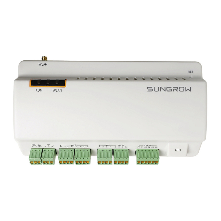
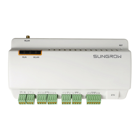
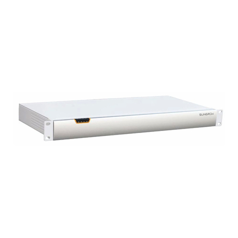
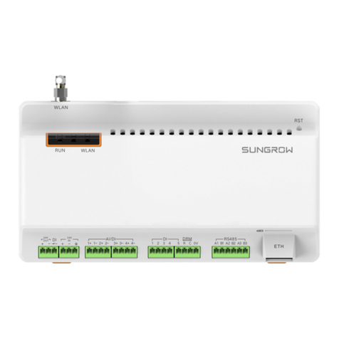
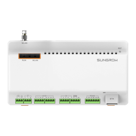
Sungrow Logger3000 User manual

LLooggggeerr33000000DDaattaa LLooggggeerrUUsseerr
MMaannuuaallLLooggggeerr33000000--UUEENN--VVeerr1177--
220011990044
Logger3000-UEN-Ver17-201904
Logger3000
DDaattaa LLooggggeerr
UUsseerr MMaannuuaall


I
CCoonntteennttss
1 About this Manual ....................................................................................... 1
1.1 Validity ......................................................................................................... 1
1.2 Target Group................................................................................................ 1
1.3 Symbol Explanations.................................................................................... 1
1.4 How to Use This Manual............................................................................... 3
2 Safety Instructions ...................................................................................... 4
3 Product Introduction ................................................................................... 6
3.1 Function Description .................................................................................... 6
3.2 Application scenario..................................................................................... 7
3.3 Appearance................................................................................................. 9
3.3.1 Appearance........................................................................................ 9
3.3.2 Dimensions ...................................................................................... 10
4 Installation Flow ......................................................................................... 11
5 Unpacking and Storage ........................................................................... 13
5.1 Scope of Delivery....................................................................................... 13
5.2 Identifying the Logger3000 ........................................................................ 14
5.3 Checking upon Receiving........................................................................... 14
5.4 Storage...................................................................................................... 15
6 Mechanical Installation ............................................................................ 16
6.1 Location Selection...................................................................................... 16
6.2 Installation Tools......................................................................................... 16
6.3 Installing Logger3000................................................................................. 17
6.3.1 Wall-Mounted Installation ................................................................. 17
6.3.2 Rack-mounted Installation ................................................................ 19
7 Electrical Connection ............................................................................... 21
7.1 Safety Instructions...................................................................................... 21
7.2 Port Introduction......................................................................................... 21
7.3 Overview.................................................................................................... 23
7.4 RS485 Port ................................................................................................ 23
7.4.1 Connecting to the Device with RS485 Port ........................................ 23

II
7.4.2 Connecting to the Device with RJ45 Port........................................... 25
7.4.3 Connecting to the Meteo Station ....................................................... 26
7.4.4 Connecting to the Energy Meter........................................................ 27
7.5 Ethernet Port.............................................................................................. 28
7.6 PLC Port..................................................................................................... 29
7.7 Connecting to the AC Power Supply ........................................................... 30
7.8 Connecting to the DC Power Supply ........................................................... 31
7.9 Earthing Connection................................................................................... 32
8 Commissioning ........................................................................................... 33
8.1 Inspection before Commissioning .............................................................. 33
8.2 Commissioning Steps................................................................................. 33
9 Web Interface ............................................................................................. 34
9.1 Running Requirements............................................................................... 34
9.2 Preparation before Login............................................................................ 34
9.3 Login Steps................................................................................................ 34
9.4 Web Interface ............................................................................................ 35
9.5 Web Menus ............................................................................................... 36
9.6 Operation Flow........................................................................................... 36
9.7 Monitoring.................................................................................................. 37
9.7.1 View Real-Time Data ........................................................................ 37
9.7.2 Single-Parameter Setting.................................................................. 38
9.7.3 Batch Setting.................................................................................... 38
9.7.4 Parameter Readback........................................................................ 38
9.7.5 Checking the Parameter Setting Log................................................. 38
9.8 Device Management.................................................................................. 38
9.8.1 Searching Device ............................................................................. 39
9.8.2 Device Operation.............................................................................. 41
9.8.3 Firmware Upgrade ........................................................................... 43
9.9 System Setting........................................................................................... 43
9.9.1 SystemTime Setting.......................................................................... 43
9.9.2 Serial Port Setting ............................................................................. 44
9.9.3 Network Setting................................................................................ 44
9.9.4 Restarting......................................................................................... 45
9.9.5 Modbus Service ............................................................................... 45
9.9.6 IEC104 Service Settings ................................................................... 46
9.9.7 IEC104 Main Protocol Settings (Optional).......................................... 46

III
9.9.8 Cloud Service Setting........................................................................ 47
9.9.9 Country and Region Setting .............................................................. 49
9.9.10 About ............................................................................................. 49
9.10 Maintenance............................................................................................ 49
10 Grid Dispatching ...................................................................................... 51
10.1 Function Description ................................................................................ 51
10.2 Grid Dispatching Plans ............................................................................. 51
10.3 EMU Setting............................................................................................. 52
10.4 Local Power Regulation............................................................................ 54
10.5 BDEW...................................................................................................... 56
11 Maintenance ............................................................................................. 57
11.1 Safety Instructions.................................................................................... 57
11.2 Maintenance List...................................................................................... 58
12 Troubleshooting ....................................................................................... 59
12.1 Safety Instructions ................................................................................... 59
12.2 Common Faults and Corrective Measures ................................................ 59
13 FAQ .............................................................................................................. 64
14 Appendix A: Technical Data ................................................................. 66
15 Appendix B: Related Drawings ........................................................... 67
16 Appendix C: General Information ....................................................... 68
16.1 Quality Guarantee .................................................................................... 68
16.2 Contact Information ................................................................................. 68


1
1 About this Manual
1.1 Validity
This manual is valid for the following data loggers:
•Logger3000
1.2 Target Group
This manual is applicable to technical personnel who are responsible for the installation,
operation and maintenance of the Logger3000 and to users who need to perform daily
operation. Readers should have the following qualifications:
•Have some knowledge of electrical and electric cabling and mechanical knowledge;
and be familiar with electrical and mechanical diagrams.
•Be familiar with the PV grid-connected power generation system and its working
principle.
•Have received professional training in installing and commissioning of the electrical
devices.
•Be capable of handling the danger or emergency that may occur during installation
or commissioning.
•Be familiar with the national/local standards and regulations.
•Be familiar with the description in this manual.
Only personnel meeting the foregoing requirements can conduct installation,
maintenance, and troubleshooting. Unauthorized personnel is prohibited to perform any
operation on the device.
1.3 Symbol Explanations
WWaarrnniinngg LLaabbeell
Warning label on enclosure of the Logger3000 is as follows:

2
SSyymmbboollss EExxppllaannaattiioonn
Disconnect the Logger3000 from all the external power sources before
service!
Hot surface! Do not touch!
Risk of electric shock! If not avoided, lethal hazard can be caused.
Do not touch live parts until 30second after disconnection from the
sources!
Check user manual before service!
SSyymmbboollss
This manual contains important safety and operational instructions that must be
accurately understood and respected during the installation and maintenance of the
equipment.
To ensure the optimum use of this manual, note the following explanations of the
symbols used.
DANGER indicates a hazard with a high level of risk which, if not avoided, will
result in death or serious injury.
1 About this Manual User Manual

3
WARNING indicates a hazard with a medium level of risk which, if not avoided,
could result in death or serious injury.
CAUTION indicates a hazard with a low level of risk which, if not avoided, could
result in minor or moderate injury.
NOTICE indicates a situation which, if not avoided, could result in equipment or
property damage.
NOTE indicates additional information, emphasized contents or tips to help
you solve problems or save time.
1.4 How to Use This Manual
Read this manual carefully before performing operation on the device. This manual
must be stored at hand and available at all times.
All rights reserved including the pictures, symbols, and markings used in this manual.
Any reproduction or disclosure, even partially, of the contents of this manual is strictly
prohibited without prior written authorization of SUNGROW. The content of the manual
will be periodically updated or revised as per the product development. It is probably
that there are changes in manuals for the subsequent module edition. If there any
mismatch between the product and its manual, the actual product shall prevail and the
manual of the latest version can be obtained from SUNGROW.
User Manual 1 About this Manual

4
2Safety Instructions
This chapter mainly introduces safety instructions that need to be respected during the
operation of Logger3000.
The Logger3000 has been designed and tested strictly according to international safety
regulations. As electrical and electronic equipment, the Logger3000 must be installed,
commissioned, operated, and maintained in strict accordance with related safety
instructions. Incorrect operation or misuse of the device may cause:
•damage to personnel safety of the operators or the third party
•damage to the Logger3000 or other properties belong to the operators or the third
party
Therefore, the following safety instructions must be read and always kept in mind prior
to any work. All detailed work-related safety warnings and notes will be specified at the
critical points in corresponding chapter.
All operations and electrical work must only be performed by qualified
personnel.
BBeeffoorree IInnssttaallllaattiioonn
After receiving the device, please check if there is damage caused during
transport. Contact SUNGROW or the forwarding company once any problem is
found.
The related operators must be familiar with the safety instructions in this manual
and other safety regulations about the installation, operation and maintenance
of the Logger3000.
Move, transport, install, operate, and maintain the Logger3000 correctly and
appropriately.
DDuurriinngg IInnssttaallllaattiioonn
The Logger3000 can only be used as described in this manual. Altering the
product without authorization or using spare parts not sold or recommended by
SUNGROW may lead to fire, electric shock or other damages.

5
Disconnect all electrical connections and the upstream input switch and make
sure the Logger3000 is voltage-free during installation.
MMaaiinntteennaannccee aanndd RReeppllaacceemmeenntt
The maintenance of the Logger3000 can only be performed by qualified
personnel from SUNGROW or other qualified personnel.
User can never maintain or replace the modules and other parts. Serious
personal injury or property loss may follow if otherwise.
Never replace the internal components of the Logger3000 without
authorization. SUNGROW shall not be held liable for any possible damage
caused by ignorance of this warning.
User Manual 2 Safety Instructions

6
3 Product Introduction
3.1 Function Description
The Logger3000 is equipped with the following functions:
SSuuppppoorrtt ooff DDeevviiccee CCoonnnneeccttiioonn
The Logger3000 can be connected to devices in the PV system via an RS485 bus, and
it can be also connected to SUNGROW string inverter equipped with the PLC
communication function through the PLC cable. The Logger3000 can store and process
device information as well as convert data communication protocol.
MMaannaaggeemmeenntt ooff CCoommmmuunniiccaattiioonn DDeevviiccee
The Logger3000 can centrally manage devices connected to it, including parameter
setting, firmware upgrade, etc, which makes onsite maintenance more convenient.
CCoonnffiigguurraattiioonn tthhrroouugghh WWEEBB IInntteerrffaaccee
Users can set system time, network, serial port, etc. and maintain the protocol point
table through the embedded WEB interface of the Logger3000.
DDaattaa FFoorrwwaarrddiinngg SSeerrvviiccee
The Logger3000 can forward collected data to cloud platform, for example, iSolarCloud.
PPrroottooccooll CCoonnvveerrssiioonn SSeerrvviiccee
The Logger3000 provides protocol conversion service, including converting
ModbusRTU into IEC104, MQTT, etc.
GGrriidd DDiissppaattcchhiinngg
The Logger3000 can receive and execute dispatching instructions from the grid,
including remote IEC104 instructions, remote dispatching from Japan utility power
company, and AI/DI dispatching control instructions.
The Logger3000 can perform active power control and reactive power regulation on the
inverter connected to it.
LLooccaall DDiissppaattcchhiinngg
The Logger3000 can receive and execute local dispatching instructions, including
delivering fixed value, energy meter closed-loop dispatching, etc.
II--VV CCuurrvvee SSccaannnniinngg
The Logger3000 can perform I-V curve scanning on SUNGROW inverter, and users can
view scanning result via iSolarCloud or Insight. For detailed description of the I-V curve
scanning, refer to the manual of iSolarCloud or Insight.

7
3.2 Application scenario
The Logger3000 is connected to the inverter, transformer, Meteo Station, and energy
meter in the PV system via RS485 bus, or it can be connected to SUNGROW string
inverter equipped with PLC communication function through PLC (power line carrier
communication) bus.
The Logger3000 sends the collected data to Insight or a third-party server via a core
switch, and then the background sends the data to iSolarCloud through a router.
CCoonnnneeccttiioonn tthhrroouugghh SSoorree SSwwiittcchh
The following figures shows how the Logger3000 is connected to the Insight or
iSolarCloud through a core switch.
ffiigguurree 33--11 Ring networking
User Manual 3 Product Introduction

9
CCoonnnneeccttiioonn tthhrroouugghh RRoouutteerr
As shown in the figure below, the Logger3000 can be directly connected to the
iSolarCloud through a router.
3.3 Appearance
3.3.1 Appearance
Appearance of the Logger3000 is shown in the following figure.
NNoo.. DDeessccrriippttiioonn
A Indicator
B Mounting ear
CWiring terminal
User Manual 3 Product Introduction

10
IInnddiiccaattoorr
IInnddiiccaa--
ttoorr
NNaammee DDeessccrriippttiioonn
PWR Power
indicator
On: power supply is normal; Off: power supply is
abnormal
RUN Running
indicator
Flashing: running is normal; Off: running is abnormal
BLE Bluetooth
indicator Reserved
FAULT Fault indicator On: fault occurs in connected inverter; Off: connected
inverter is free of fault
3.3.2 Dimensions
3 Product Introduction User Manual

11
4 Installation Flow
The following figure shows the overall installation flow of Logger3000.
NNoo.. PPrroocceedduurree RReeffeerreennccee cchhaapptteerr
1Unpacking and inspection "5.1 Scope of Delivery"
2Read the user manual,
especially "Safety Instructions" "2 Safety Instructions"
3
Store the Logger3000 properly
if it is not to be installed
immediately
"5.4 Storage"
4Installation location selection "6.1 Location Selection"
5 Mechanical installation "6 Mechanical Installation"
6 Electrical installation "7 Electrical Connection"

13
5Unpacking and Storage
5.1 Scope of Delivery
Check the scope of delivery for completeness according to the packing list. The
following items should be included.
NNoo.. NNaammee DDeessccrriippttiioonn
ALogger3000 -
B Documents Quick User Manual, quality certificate, packing list,
product test report, and warranty card
CCommunication terminal
resistor
(Note: if there are more than 15 devices
connected on the RS485 bus, it is recommended
to connect a 120Ω terminal resistor in parallel on
the A and B lines at the head or tail end of the
bus)
D Ethernet cable 1x2m
E GPS antenna Optional
FMounting ear 2
GBottom supporter 2
H PLC cable 2 x1m
I OT terminal RNBL5-4
JNylon cable tie Used to tie cables

14
NNoo.. NNaammee DDeessccrriippttiioonn
K
Tapping screw assembly 8, including ST4.8x19 expansion bolts and
tapping screws, used for wall-mounted
installation
L Fastener assembly
6, M4x8 cross recessed countersunk head
screws, used to anchor the mounting ears to the
Logger3000
5.2 Identifying the Logger3000
The type and key technical parameters of the Logger3000 can be found on the
nameplate. The nameplate is attached to the upper right corner of the Logger3000,
shown by A in the figure below.
The nameplate contains important parameters. Ensure it is intact and clearly
legible.
5.3 Checking upon Receiving
The Logger3000 is thoroughly inspected and packed before delivery, but damage may
be still caused during transport. Check the following items carefully once receiving the
Logger3000.
•Check the scope of delivery for completeness according to "5.1 Scope of Delivery".
•Ensure that the device type is correct.
•Check the device thoroughly and ensure there are no visible damages.
If there are any problems, contact SUNGROW or the forwarding company.
Only undamaged Logger3000 can be installed and commissioned. Before
installation, ensure that:
•The Logger3000 is intact without any damages.
•Related documents, such as quick user manual, are enclosed.
5 Unpacking and Storage User Manual
Other manuals for Logger3000
1
Table of contents
Other Sungrow Data Logger manuals

Sungrow
Sungrow Logger3000 User manual

Sungrow
Sungrow Logger4000 User manual

Sungrow
Sungrow 1000A User manual

Sungrow
Sungrow Logger1000 User manual

Sungrow
Sungrow Logger1000A User manual

Sungrow
Sungrow Logger1000B User manual

Sungrow
Sungrow Logger1000A User manual

Sungrow
Sungrow Logger1000A User manual

Sungrow
Sungrow Logger 3000 User manual