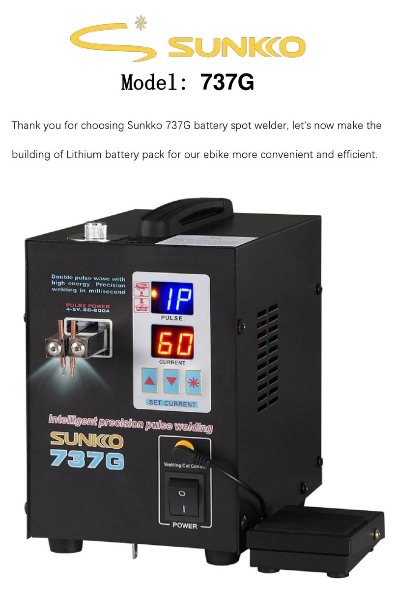
Sunkko 737G User manual

----
*
c
____
::>
....
SUNKCO
787G
Dual
digital
display
intelligent
precision
pulse
spot
welder
Thank you for choosing
SUNK<O
series of products. These products are
designed to make your work more convenient, safe and efficient. Such
that you might become familiar with all the operations of the welder,
an
instruction manual has been included.
INSTRUCTION MANUAL
Attention : Please make sure the GFCI (Ground Fault Circuit Interrupter)
is
up
to
60A or more before turn
on
the spot welder.
In
order to obtain good weld effect, please don't use the active socket,
and should
be
used the wall socket to ensure stable power supply.
Please store this manual
in
a safe location for both current and future
reference.

Catalogue
.
~~
A.
Showing
®
B.
Introduction
......
®
c.
Panel
i
ntrod
uction
.
.........
(4)
D.
Welding
introduction
................. @
E.
Attention
to
use
...... ...... .
..
.
....
.. .....
.....
.
...
®
o

j
I
<
A.
Showing "
liw).!.
Welding
pressure
adjuster
Fixed
welding
head
LED light
Machine
leg
---
Handle
Parameter tag
QC
Tag
---
Welding pulse
'-----
Percentage of current
'------
Setting keys
Pedal interface
fL-
--
Power switch
----
Cooling hole
e-----
Fuse
~---
Power cord
•

"''.-
B.
Introduction
j~
The
SUNKKO
737G is a
precision
spot
welding
machine
which
is
designed
to
enhance
the
welding
of
thin
metals
wi
thout
excessive
heat
buildup.
Parameter
A. Welding
part
1.
Input
voltage
:
AC
11
OV/220V
Please
check
your
machine
's
suitable
voltage
to use.
2.
Primary
current:
2A-1SA
Welding
current:
SOA-800A
The
width
of
1
pulse
time
: O.S-Sms(Variable)
The
width
of
2
pulse
time
: 1-1 Oms(Variable)
B.
Net
weight:
4.3KG
C. Size:
140x24Sx200mm
D.
Welding
thickness
: 0.OS-0.2mm
(1
pulse
: 0.OS-0.
12mm
; 2
pulse
:
0.12-0
.
2mm)
E.
Work
cycle:
less
than
20
times
in 1
minute
for
intermittent
welding
.
Summary
1.
Use
micro
chip
for
controlling
precision
current
to
weld
in
precision.
2.
There
are
wide
range
of
selecting
current
(1
12
pulse)
can be
selected
to
make
your
work
more
convenient
,
safe
and
efficient.
3.
Controlled
by
micro
computer.
4.
Welding
power
can be
set
and
displayed
on Led panel.
S. It is
suitable
for
welding
charging
battery
pack
,
button
cell
leads
,
hardware
to
process
, etc.
Range
Of
Application
1. Welding different kinds of rechargeable battery wi
re
lead.
2.Assembling and welding lithium battery and mobile power.
3. Repairi
ng
battery packs.
4.Welding lead sheets and wire of hardware parts.
Packing
list
1,
Machine*1
4,
Foot
Pedal
*1
7,
20
or
30A
fuse
*2
2,
Instruction
manual
*1
5,
Hex
wrench
*1 3,
Warranty
card
*1
6,
Welding
pins*4

c.
Panel
introduction
i\7
Operation
1.
Please
turn
off
the
machine
before
install
welding
pins on.
2.lnsert
the
power
cord on the wall
socket.
Turn on
the
power
switch.
3.Setting
"
Current"
"
Pulse
".
Pressing
"
*"
to
select
and
confirm
.
Ind
icator light
ofweldi
ng
mode
Pulse
---
(1
P-2P
can
be
selec
t
ed
)
Percentage of current
(0-99
ad
justable)
...
UP
..!!!!!!!
!!iI
i - i T DOWN
*Confirm
(1)
The
second
row
of
first
and
second
digit
show
the
volume
of
current.
Press
" * ",
the
fi
st
di
git
will
blink
,
that
means
the
parameter
can be
adjusted
via
"UP"
and
"
DOWN
".
Press
" * "
again
to confirm.
(2)
The
second
digit
will
bl
ink
,
that
means
the
parameter
can be
adjusted
via
"UP"
and
"
DOWN
".
Press
" * "
again
to
confirm.
(3)
P2 or
P1
will
blink.
Please
select
P2
or
P1
via
"UP"
and
"
DOWN
"
to
set
the
pulse
. P2
means
welding
once
in 2
times.
P1
means
welding
once
in 1
time.
(4)
Press
" * "
again
to
confirm
.
The spot
we
lder can weld when the digit not blink.
(S)
Please
set
bi
gger
current
power
to
weld
thicker
than
0.1mm.
(6) The t
ab
le of current and time of pulse for number setting and
knob setti
ng
.
Input
voltage
AC
11
OV
1220V
Power
2.8
KW(lnstaneous max)
Ti
me
of 1 pulse O.S-Sms
(Variable)
Time of 2
pu
l
se
1-1 Oms
(Variab
le)
o

,
D.
Welding introductio[l
1.Welding
pressure
adjuster
Please
turn up the
pressure
adjuster
in
clockwise
to
weld
thicker
thickness
.
Please
turn
down
the
adjuster
in
anticlockwise
to weld
thinner
thickness.
Please
observe
the
welding
spot
wether
fastness
and
small
size.
(Notice:
When the
pressure
adjuster
to
the
maximum
or
minimum will be
not
welded
.
Please
turn the knob to
other
side and the
machine
can
work
again.)
~ypesof
Pure nickel strip Nickel plated strip
Please for reference
to adjustthe welding
pressure adjuster
Thid<ness--..<..!.......
O.
05mm
O.
1rrrn
200-220g 250-280g
250-300g
320-350g
2.
Install
welding
pins
Before After
3. Welding operation
O.
15rrrn
320-350g
350
- 40
0g
O.2rrrn
350-420g
400-480g
1. Use hexagon wrench to lossen
screw
.
2. Welding pins
get
through from below
of
the hole.
3. Adjust the length. Use hexagon wrench
to
tight
up the screws.
4.
It can be installed as you wish. But
please do not let 2 welding pins get
in
touch.
1.
0epending
on
the thickness
of
welding material to set current
and pulse.
2.
The welding pins press tight on
the welding surface and push up
the welding arm.
Press
tight
and
push
up
Finished
4. Pedal switch Please plug
on
the pedal switch into the
panel. The original welding controlling
function transferto the pedal switch to
control.
When aiming to the welding spot
and push up the welding arm. then step
the pedal switch to weld.
.,

E.
Attention to use
';~
Using
notice
1.
In
order to obtain good weld effect, please don't use the active socket,
and should
be
used the wall socket to ensure stable power supply.
2. Please place the spot welder
in
the ventilated areas to keep the
machine for heat dissipation.
3.
Please adjust the suitable welding pressure for welding.
4.
Please notice when reaching to setting temperature inside ofthe
spot welder,
it
would
be
protected and stop to work until the temperature
cooling down.
5. Please let the machine take a break when welding over O.2mm
thickness to avoid overheat.
6.
Please keep clean of weldi
ng
pins surface for obtaini
ng
good
weldi
ng
spot.
The
maintenance
of
welding
pins
1. The weldi
ng
pi
ns
on
the new machine must
be
clamped by M4
hexagon screws.
2. Please check oxidation
on
2 pin clamps and grinding
it
wi
th
crocus cloth.
3. Please check oxidati
on on
welding
pin
and gri
nd
i
ng
it with sand paper.
4.
It
can
be
smeared some lubricati
on
oil
on
welding pin clamps
and welding pins for avoidi
ng
oxidation.
Repair
of
Simple Fault
Fault
Phenomena
Treatment
The
machine
doesn
't
run
Please
check
power
and
the
Insurance
behind the
machine
.
Bad
welding
effect
Check
the
power
supply
If
less
than
200V
and
the
socket
Is
whether
connected.
Poor Welding
Check
the
position
of
welding
needle
,and
observe
the
welding
needle
If
It Is
oxldlzea
.
Adjust
the
welding
needle.
GFCI-protected
If
you use the
machine
for
the
first
tlmeeeplace
another
power
supply
circuit
or
change
SDA
GF
I.
Irregular chargering Check the output voltage whether compliance with the battery
pack;the constant current whether set reasonable.
The
ch
arg
in
g
protected
cl
osed
Reduction
of
the charging current,or use
In
a well ventilated
environment.

&
Notice
1.
In
orderto
obtain good weld effect, please don't use the
active socket, and should be used the wall socketto ensure
stable powersupply.
2. Please setthe pressure adjusterto the right parameterto
avoid welding effect
in
not good.
3. Please keep the surface welding pins clean and wipe offoxide
with sand paper.
4. Please keep the welding pin
in
sharp shape.
5. Please do notworry about the lighting
in
flash. SUNKKO 737G
is a high power machine and discharging high current
instantaneously. Because this moment is
in
20ms and it is normal.
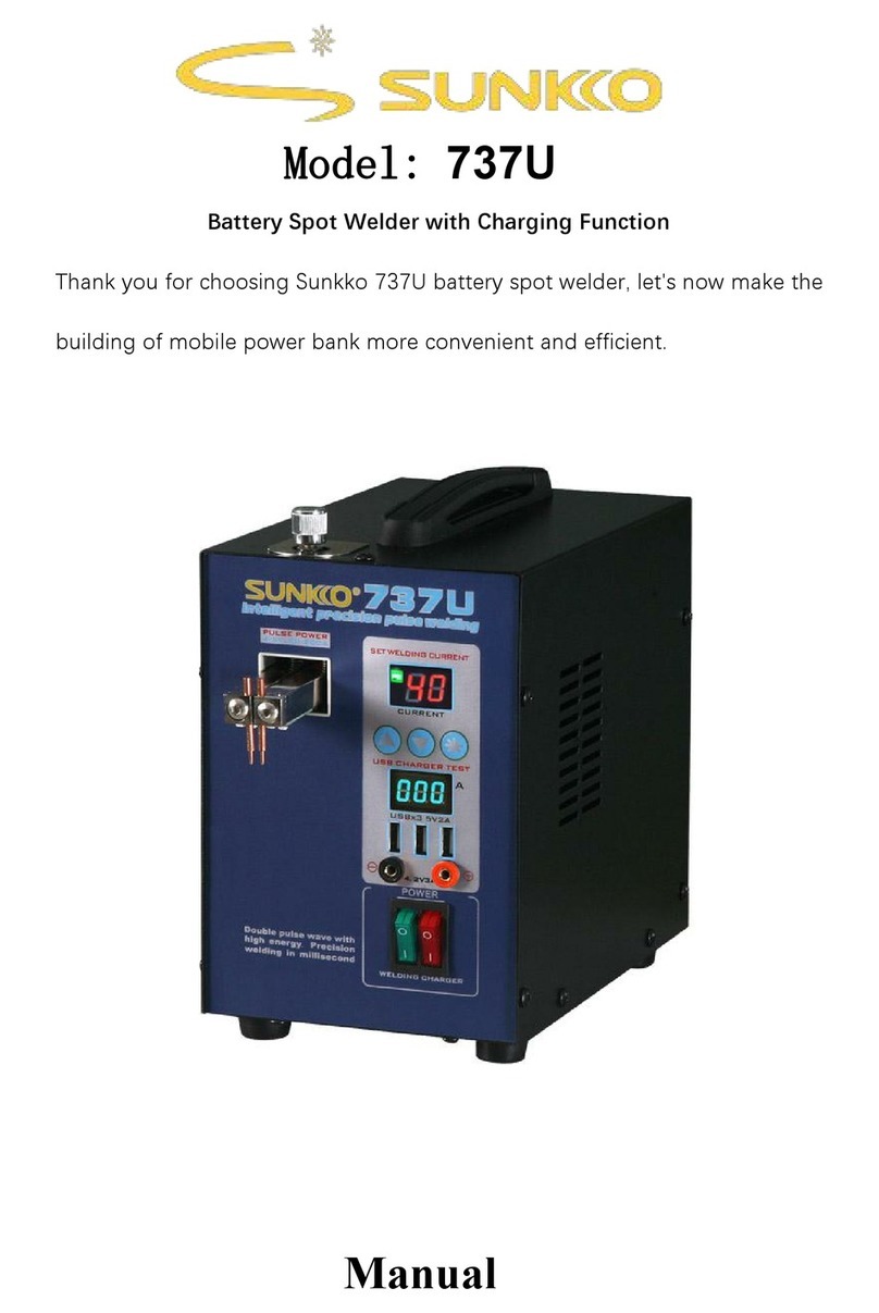
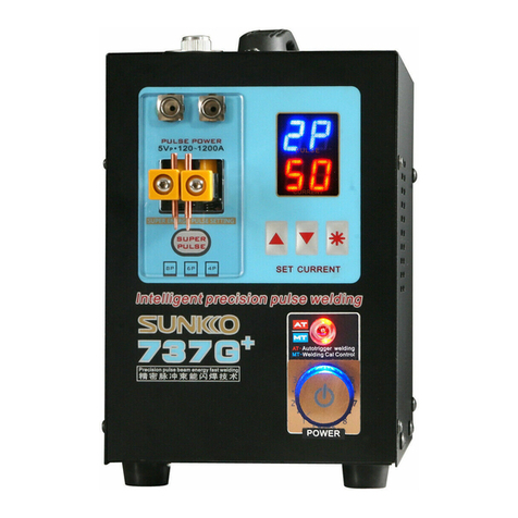
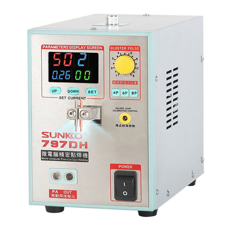
SUNKKO
709AD+
SUNKKO
788H
SUNKKO
796SD
Foshan Meilide Electronic
Co
.
Ltd
Tel
:
86
-0757-28972123/28852933
E- mail :mldsunkko@hotmail.com
Website : http:
//
sunkko.1688.com
Add : No.4 Guda Road Zhangcha,
Chancheng, Foshan, Guangdong, China.
This manual suits for next models
3
Table of contents
Other Sunkko Welding System manuals
Popular Welding System manuals by other brands

Hobart Welding Products
Hobart Welding Products AirForce 375 owner's manual

GF
GF MSA 330 instruction manual

Hakko Electronics
Hakko Electronics FX-888D instruction manual

Abicor Binzel
Abicor Binzel ABIPLAS WELD 100 W operating instructions

EWM
EWM Taurus 355 Basic TDM operating instructions

Thermal Dynamics
Thermal Dynamics PakMaster 100 XL plus operating manual