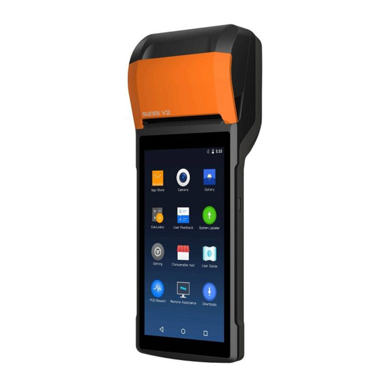
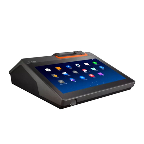
Sunmi K2 Owner's manual

K2
Kiosk User Manual Book
Before using this product, please read this manual carefully and keep it properly.

Please read the internal machine help App for more help or call 400-6666-509 for free telephone services.
The Self-Checkout Kiosk is applicable for the cashier environment of commercial customers in
various industries,such as Chinese and Western catering,high-end department stores,supermarkets,
convenience stores, information sites, interactive multi-media, scenic spot, etc. Please turn on the
Kiosk and search & download the relevant Apps on the App market on Internet.
Wall-mounted
AFloor-standing
BFloor-standing with table
CEco-service expansion
D
Four installation styles of K2 Self-service Kiosk
Quick Setting
After turning on the complete machine power supply, the screen will be lit. Then you will
enter the first boot interface and just simply operate according to the instructions.
There are two types of internet mode available for you.
Wi-Fi setting
Click “Setting” and “WLAN” to enter the WLAN search interface. Wait for the available
WLAN hot spots searching and listing. Click the right WLAN to connect to the network.
Access password is required for an encrypted network connection.
LAN setting
After plugging the network cable correctly, click “Setting” and “Wired Network” to
choose Enable. Access password is required for an encrypted network connection.
As for IP address, there are two options: to automatically obtain IP or to manually
enter IP address.
Only several steps to enable the smart commercial device K2:
Facebook:Sunmitech
LinkedIn:SUNMI Technology
Quick Start Guide
Plug the power line into the power interface.
2
Plug the network cable into the network interface.
3
Close the back plug cover.
4
Press the buttons on both side of the host
at the same time to open the flip panel.
5Press the power switch to turn on the host.
6
Open the back plug cover.
1
2
3
1
5
5
6

Open flip panel
1
1
12
4
3
Press the buttons on both side of the host at
the same time to open the flip panel.
Open paper storage cover
2
Toggle downward the printer driving lever to
open the paper storage cover.
Put in paper
3
Put in the 80mm thermal sensitive paper with a roller
in it and pull out a section outside the printer exit.
Close the paper storage cover and flip panel
4
Press both sides of the paper storage cover to close it.
The printer will automatically cut paper in power on state.
In power off state, it is necessary to manually tear off
excessive paper; Close the flip panel.
Paper Changing Steps for the Inside Printer
Camera used to shoot human face.
Face camera
Touchable screen applied for customer usage.
Touch screen
Used to print receipt.
Printer
Used to read codes.
Code scanner
In standby state, short press to boot, short press
again to be in standby mode;
In service state, long press for 2 to 3 seconds to
choose to shut-down or restart;
In the state of power-on,long press for 11 seconds
to shut down the host.
System switch
Used to control the host power supply.
Host switch
Face camera
Touch screen
Printer
Host switch
Nameplate
System switch
Code scanner
Trumpet
NFC
Indicator light
· Supports reading and writing of M1\ID\CPU card.
NFC
Brief Introduction of Self-Service Kiosk

Wall-mounted
AFloor-standing
BFloor-standing with table
CEco-service expansion
D
Installation Steps of the Four Types of Self-Service Kiosk
Inside the host. Mainboard external interfaces, like USB port,
TF card port, etc, will be exposed after opening it.
Protection cover on the mainboard
Used to cover the face camera inside the host.
Camera maintain cover
A wired network socket.
Wired network interface
Used to plug the power line.
Power interface
Used for external hardware equipment.
USB interface
On the mainboard and used for software update
and debugging.
Micro-USB debug port
Protection cover on the mainboard
Power supply switch
Wired network interface
Camera maintain cover
Micro-USB debug port
USB interface
Power interface

Installation Components
A Wall-mounted: B Floor-standing: C Floor-standing with table: D Eco-service expansion:
Host
1
Mainboard maintain
cover
3
Screw
5
Host back hanger
2
Wall-mounted rack
4
Back plug cover
6
Host
1
Mainboard maintain
cover
3
Stand
5
Host back support
2
Back plug cover
4
Screw
6
Line cover
7Baseplate
8
Mainboard maintain
cover
Stand
Host back support
Back plug cover
Screw
Line cover
Baseplate
Host
1
3
5
2
4
6
Table
7
9
8
Mainboard maintain
cover Back plug cover
Stand
Screw Line cover
Baseplate
Host back supportHost
1
3
5
2
4
Plastic front shell
6
7
9
8
1
1 1 1
2
222
3
333
4
45
5
5
5 6
6
6
8
8
8
99
6
4
4
7
7
7

Drill holes on the wall
1
Drill Ø10 holes according to the height and
spacing described in the reference drawing.
Install the wall-mounted rack
2
Firmly fix the wall-mounted rack on the wall by four M8X50
expansion bolts and four M6X50 expansion screws.
Install the host back hangers
3
Fix the two host back hangers with host by four M6X12 screws;
Plug in the power line and network cable.
A Installation Steps of Wall-mounted
283
280
1130
Hang the host
4
Firmly hang the host back hangers on the
wall-mounted rack.

1
3
45
5
67
8
9
2
Preassemble the stand on the baseplate
1
Preassemble the stand on the baseplate by two
M10X20 screws and do not twist them too tightly.
Fix the stand on the baseplate
2
Twist four M10X20 screws from the bottom of the
plate as shown in the picture and fasten them.
Then fasten the all the screws.
Insert the host back support
3
Insert the host back support into the stand.
Fix the back support with stand
4
Fix the back support with stand by six
M6X12 screws.
Hang the host
5
Hang the host onto the back support.
Fix the back support and host
6
Fix the back support and host by four M6X30 screws.
Assemble the mainboard maintain cover
7
Assemble the mainboard maintain cover onto the host.
Plug lines
8
Plug power line and network cable and cross the lines
through the stand. Fix the back plug cover.
Assemble the line cover
9
Push forward to fix the line cover onto the stand.
B Installation Steps of Floor-standing

Preassemble the table support screws
10
Twist two M6X12 screws into the stand for 5-10 rounds.
Preassemble the table
11
Hang the table support onto the two screws.
Fix the table
12
Fix the table with stand by four M6X12 screws
and fasten all the screws.
Separate the stand
1
Separate the plastic front shell from the metal stand carefully.
Fix the stand on the baseplate
2
Fix the stand on the baseplate by four M10X20 screws.
C Installation Steps of Floor-standing with Table
(The same installation steps of the baseplate, stand and host with the Floor-standing)
D Installation Steps of Eco-service expansion
10
12
1
2
11

Insert host back support
3
Insert the host back support into the stand.
Fix the back support with the stand
4
Fix the back support with the stand by six M6x25 screws.
Fix the plastic front shell
5
Fix the plastic front shell onto the metal stand again by clips.
Fix the host with back support
6
Hang the host onto the back support
and fix them by four M6X25 screws.
Assemble the mainboard maintain cover
7
Fix the mainboard maintain cover on the host.
Plug lines
8
Plug power line and network cable and cross the
lines through the stand. Fix the back plug cover.
Fix the line cover
9
Twist the screws to fix the metal line cover.
3
4
5
67
8
9

Basic Parameters of K2
Input:AC100~240V,Output:DC12/24V
WiFi
Printer
2.4/5 GHZ,support IEEE 802.11a/b/g/n
Support Bluetooth 2.1/3.0/4.0, Support BLE
58/ 80mm thermal printing with automatic cutter
Bar code scanning Support 1D & 2D code of mobilephone screen or Paper
Face camera 3D camera with structured light
NFC Supports reading and writing of M1\ID\CPU card
Trumpet
External interface
Extended Memory
Power supply
Temperature:0℃~40℃,Humidity:25%~90%Operational environment
Temperature:-20℃~55℃,Humidity:93%(40℃,non-condensing)Storage environment
2x3W (stereo)
4x USB typeA,1x RJ45 LAN,1x Micro-USB debug port
1x3.5 Headphone jack,1xPower interface
Support MicroSD(TF),up to 128GB
Bluetooth
F4E00
Touch screen
Ethernet 1*LAN:10/100/1000M adaptive
Operating system
Processor
Storage
Android 7.1.2(SUNMI OS)
Rockchip RK3399
Memory:16G ROM+4G RAM
24”TFT-LCD display screen,resolution:1080*1920;ten point touch capactive screen
Product model
Package packing List of K2 Host
K2 Host
K2 Wall-mounted rack
K2 Host back hanger
K2 Host back support
Accessory Box
Printing paper
Host power line(National standard)
Host network cable
Host keys
Screw bag
User Guige
1
1
1
1
1
1
1
1
2
1
1
(Wall-mounted)
(Wall-mounted)
(Floor-standing、Floor-standing without table、Eco-service expansion)
In accessory box
In accessory box
In accessory box
In accessory box(optional)
In accessory box
Including packing content, warranty card and certificate
Packing & Shipping Parameters of Complete Machine
Outline size
Weight of machine
Host: 394mm width × 171mm depth × 920mm height
Wall-mounted:17kg;Floor-standing:52kg;Floor-standing with table:56kg;Eco-service expansion:62.5kg
Host packing:523mm width × 1110mm length × 371mm depth,weight:21.7kg
Stand packing (Floor-standing with table):368mm width × 958mm length × 250mm depth,weight:17kg
Table packing (Floor-standing with table):553mm width × 1120mm length × 265mm depth,weight:12kg
Baseplate packing (Floor-standing with table):510mm width × 666mm length × 40mm depth,weight:20.3kg
Stand packing (Floor-standing):494mm width × 968mm length × 250mm depth,weight:16.6kg
Baseplate packing (Floor-standing):510mm width × 556mm length × 40mm depth,weight:17kg
Stand packing (Eco-service expansion):495mm width × 968mm length × 266mm depth,weight:20kg
Baseplate packing (Eco-service expansion):510mm width × 556mm length × 40mm depth,weight:17kg
Wall-mounted rack packing:315mm width × 366mm length × 37mm depth,weight:2.35kg
Package size/
package weight

Manufacture:Shanghai SUNMI Technology Group Co.,Ltd.
Address: Room 605, Building 7, No. 388, Songhu Rd,Shanghai, China.
Mail:[email protected]
Phone:400-6666-509
Product certificate
Inspection Qualified
Free warranty is not available for:
· Dismantle and repair the product without permission.
· The bar code and fragile stickers of the product are
damaged,and the warranty card is altered or incomplete.
·Failure to operate the equipment in accordance with
the instructions.
· Artificial damage caused by failure, scratch or damage
due to water inflow or falling.
· Failure or damage caused by force majeure.
· Beyond the warranty period.
Contact information:
· Company address:
· Contact number:
Product warranty card
Product Name:
Product model:
Product No.:
Date of purchase:
Warranty period: from the date of purchase, our company
provides day warranty service.
Table for Names and Content Identification of Toxic
and Hazardous Substances in this Product
Points for Attention
The End
FCC Statement
·Please take attention that changes or modification not expressly
approved by the party responsible for compliance could void the
user’s authority to operate the equipment.
·This device complies with Part 15 of the FCC Rules.Operation is
subject to the following two conditions:
·(1)This device may not cause harmful interference,and
·(2)This device must accept any interference received, including
interference that may cause undesired operation.
·This equipment complies with FCC radiation exposure limits set
forth for an uncontrolled environment. This equipment should be
installed and operated with minimum distance 20cm between the
radiator & your body.
CE certification information (SAR)
This device was tested for typical body-worn operations with
the back of the handset kept 0mm away.To maintain
compliance with RF exposure requirements,use accessories
that maintain a 0mm separation distance between the user's
body and the back of the handset.The use of belt clips,holsters
and similar accessories should not contain metallic components
in its assembly.The use of accessories that do not satisfy these
requirements may not comply with RF exposure requirements,
and should be avoided.
If you are using pacemaker,hearing aid,cochlear implant or other
device,please use the phone according to the doctor’s advice.
Safety warning
Please plug the AC plug into the AC socket corresponding
to the identifcation input on the power adapter of the
accessory;
·It is strictly forbidden to use it at a site with the existence
of any potential explosive gas;
·Non-professionals are not allowed to open the internal
module at will, to avoid danger.
·This is a A grade product. In the living environment, this
product may cause radio interference.
In this case, the user maybe required to apply feasible
measures against the interference.
Suggestions
·Do not use it near the water or in the humid environment, to
prevent the liquid from dropping into the terminal;
·Do not use it in extreme cold or hot environment. For example:
near the ignition source or lighted cigarette;
·Do not drop, throw or bend it;
·Try best to use it in clean and dust-free environment, to prevent
small items from dropping into the terminal;
·Do not use it nearby the medical devices when not allowed.
Statement
Our company will not be responsible for the results of the
following actions
Damage caused by usage & maintenance not under the
conditions of this guidance note;
Our company will not be responsible for any damage or
problem caused by any option or consumable (not the
initial product or recognized product provided by our
company). You have no right to make product company;
Disclaimer
Due to the product update, certain details of this document may be
inconsistent with the product.
Please refer to the material item. Our company owns the interpre-
tative right of this document. We reserve the right to modify this
user guide without giving advance notice.
Important Safety Instructions
·Avoid it to be installed or used during the thunder &
lightning period,otherwise there will be risk of being
electrically shocked by it;
·When you have discovered unusual odor, overheat or
smog, please cut off the power supply at once!
·The paper knife is relatively sharp,please don't touch it!
indicates that the content of the toxic and hazardous substance in all homogeneous materials of the component is
below the limit specified in SJ/T 11363-2006.
indicates that the content of the toxic and hazardous substance in at least one homogeneous material of the
component exceeds the limit stipulated in SJ/T 11363-2006. However, as for the reason, because there is no
mature and replaceable technology in the industry at present.
:
:
The products that have reached or exceeded environmental protection service life should be recycled and reused
according to the Regulations on Control and Management of Electronic Information Products, and should not be
discarded randomly.
Part Name Toxic or Hazardous Substances and Elements
Pb Cd Cr(VI) PBB
Circuit Board Component
Structural Component
DBPHg PBDE DEHP BBP DIBP
Packaging Component
Points for attention about the power supply
·Please unplug the plug from the power supply AC socket
to completely disconnect the power supply connection of
the device;
·The power supply socket should be installd near the
device, and be easy to contact.
Table of contents
Other Sunmi Touch Terminal manuals

Sunmi
Sunmi T2 series Owner's manual

Sunmi
Sunmi T2SL User manual

Sunmi
Sunmi V2 User manual

Sunmi
Sunmi T1 mini Owner's manual

Sunmi
Sunmi T2 MINI Owner's manual

Sunmi
Sunmi V2 PRO T5921 User manual

Sunmi
Sunmi T2 LITE User manual

Sunmi
Sunmi BL202 User manual

Sunmi
Sunmi T2s LITE User manual

Sunmi
Sunmi T2 LITE Owner's manual