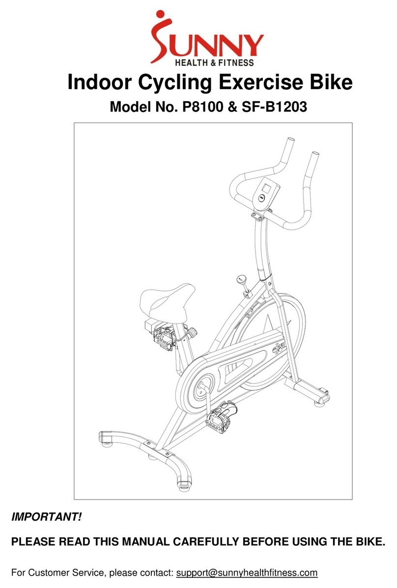
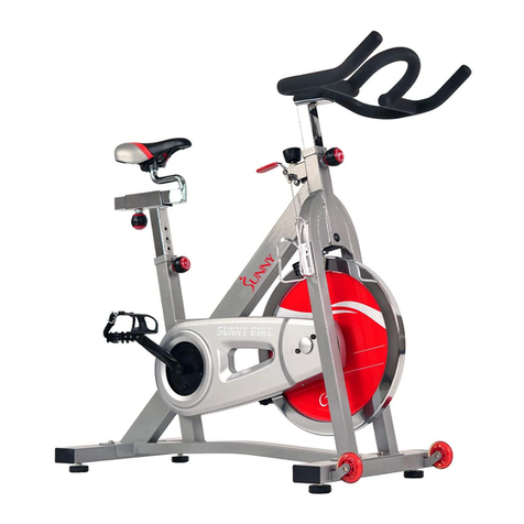
Sunny SF-B901 User manual

PRO INDOOR CYCLING BIKE
SF-B901
USER MANUAL
English, Page 9 ~ 15IMPORTANT! Please retain owner’s manual for maintenance and adjustment instructions. Your satisfaction is
very important to us, PLEASE DO NOT RETURN UNTIL YOU HAVE CONTACTED US:
support@sunnyhealthfitness.com or 1- 877 - 90SUNNY (877-907- 8669).
Español, Página 16 ~ 22¡IMPORTANTE! Conserve el manual del propietario para las instrucciones de mantenimiento y ajuste. Su
satisfacción es muy importante para nosotros, NO DEVUELVA HASTA HABERNOS CONTACTADO:
support@sunnyhealthfitness.com ó 1- 877 - 90SUNNY (877-907-8669).
Français, Page 23 ~ 29 IMPORTANT! Veuillez conserver le manuel du propriétaire pour les instructions de réglage et d’entretien.
Votre satisfaction est très importante pour nous, VEUILLEZ NE PAS EFFECTUER DE RETOUR AVANT DE
NOUS AVOIR CONTACTÉ : support@sunnyhealthfitness.com ou 1- 877 – 90SUNNY (877-907-8669).
Deutsche, Seite 30 ~ 36 WICHTIG! Bitte bewahren Sie das Benutzerhandbuch für Wartungs- und Einstellanweisungen auf. Ihre
Zufriedenheit ist besonders wichtig für uns, BITTE SCHICKEN SIE DAS PRODUKT NICHT ZURÜCK,
BEVOR SIE SICH MIT UNS IN VERBINDUNG GESETZT HABEN: support@sunnyhealthfitness.com
oder 1-877-90SUNNY (877-907-8669).

1
IMPORTANT SAFETY INFORMATION
We thank you for choosing our product. To ensure your safety and health, please use this equipment correctly. It is important to read
this entire manual before assembling and using the equipment. Safe and effective use can only be achieved if the equipment is
assembled, maintained and used properly. It is your responsibility to ensure that all users of the equipment are informed of all warnings
and precautions.
1. Before starting any exercise program, you should consult your physician to determine if you have any medical or physical
conditions that could put your health and safety at risk or prevent you from using the equipment properly. Your physician’s advice
is essential if you are taking medication that affects your heart rate, blood pressure or cholesterol level.
2. Be aware of your body’s signals. Incorrect or excessive exercise can damage your health. Stop exercising if you experience any of
the following symptoms: pain, tightness in your chest, irregular heartbeat, shortness of breath, lightheadedness, dizziness or
feelings of nausea. If you do experience any of these conditions, you should consult your physician before continuing with your
exercise program.
3. Keep children and pets away from the equipment. The equipment is designed for adult use only.
4. Use the equipment on a solid, flat level surface with a protective cover for your floor or carpet. To ensure safety, the equipment
should have at least 4 feet (120 CM) of free space all around it.
5. Ensure that all nuts and bolts are securely tightened before using the equipment. The safety of the equipment can only be
maintained if it is regularly examined for damage and/or wear and tear.
6. Always use the equipment as indicated. If you find any defective components while assembling or checking the equipment, or if
you hear any unusual noises coming from the equipment during exercise, discontinue use of the equipment immediately and do
not use until the problem has been rectified.
7. Wear suitable clothing while using the equipment. Avoid wearing loose clothing that may become entangled in the equipment.
8. Do not place fingers or objects into the moving parts of the equipment.
9. The maximum weight capacity of this unit is 275 pounds (125 KG).
10. The equipment is not suitable for therapeutic use.
11. To avoid bodily injury and/or damage to the product or property, proper lifting and moving is required.
12. Your product is intended for use in cool, dry conditions. You should avoid storage in extreme cold, hot or damp areas as this may
lead to corrosion and other related problems.
13. This equipment is designed for indoor and home use only. It is not intended for commercial use.
INFORMACIÓN IMPORTANTE DE SEGURIDAD
Gracias por haber elegido nuestro producto. Para garantizar su seguridad y salud, utilice este equipo correctamente. Es importante
que lea todo el manual antes de instalar y usar el equipo. Solo se puede garantizar el uso seguro y eficaz del equipo si se instala,
mantiene y utiliza correctamente. Es su responsabilidad asegurarse de que todos los usuarios de los equipos conozcan todas las
advertencias y precauciones.
1. Antes de comenzar algún programa de ejercicios, deberá consultar con su médico para determinar si tiene alguna condición
médica o física que pudiera poner en riesgo su salud y seguridad o que pudiera impedir que utilice correctamente el equipo. Es
importante que reciba las recomendaciones de su médico en caso de que esté tomando algún medicamento que pudiera afectar
su ritmo cardíaco, presión arterial o nivel de colesterol.
2. Esté atento a las señales que le envía su cuerpo. Ejercitarse de manera incorrecta o excesiva puede dañar su salud. Deje de
hacer ejercicio si experimenta alguno de los siguientes síntomas: dolor, opresión en el pecho, latidos cardíacos irregulares, falta
de aire, sensación de desmayo, mareos o sensación de náuseas. Si presenta alguna de esas condiciones, deberá consultar con
su médico antes de continuar con su programa de ejercicios.
3. Mantenga el equipo lejos del alcance de niños y mascotas. El equipo está diseñado para el uso exclusivo de adultos.
4. Utilice el equipo en una superficie plana y sólida con una cubierta protectora para su piso o alfombra. Para garantizar su
seguridad, el equipo debe tener por lo menos 4 pies (120 cm) de espacio libre a su alrededor.
5. Asegúrese de que todas las tuercas y pernos estén bien ajustados antes de usar el equipo. Solo puede conservarse la seguridad
del equipo si se inspecciona regularmente para detectar daños o desgaste.
6. Siempre utilice el equipo como se indica. Si encuentra algún componente defectuoso mientras instala o revisa el equipo, o si
escucha ruidos extraños que provienen de este mientras se ejercita, deje de utilizarlo inmediatamente y no lo utilice hasta que el
problema se haya corregido.
7. Use ropa adecuada cuando utilice el equipo. Evite usar ropa suelta que pueda enredarse en el equipo.
8. No coloque los dedos u objetos en las piezas móviles del equipo.
9. La capacidad de peso máximo de esta unidad es de 275 libras (125 kg).
10. Este equipo no es adecuado para uso terapéutico.
11. Muévase con cuidado cuando levante y mueva el equipo. Siempre utilice la técnica de levantamiento adecuada y pida ayuda en
caso de que sea necesario.
12. Su producto está diseñado para usarse en un lugar fresco y seco. Debe evitar tenerlo en lugares extremadamente fríos, calientes
o húmedos, ya que podría provocar corrosión y otros problemas afines.
13. ¡Este equipo está diseñado solo para uso interior! ¡No es para uso comercial!

2
INFORMATIONS DE SÉCURITÉ IMPORTANTES
Nous vous remercions d’avoir choisi notre produit. Pour votre santé et votre sécurité, veuillez utiliser correctement cet appareil. Il est
important de lire entièrement le présent manuel avant d’assembler l’appareil et de l’utiliser. L’utilisation sûre et efficace n’est possible
que si l’appareil est correctement assemblé, entretenu et utilisé. Il vous incombe de vous assurer que tous les utilisateurs de l’appareil
soient informés de tous les avertissements et précautions.
1. Avant d’entamer un programme d’exercices, consultez votre médecin pour déterminer si vous avez une quelconque disposition
physique ou médicale susceptible de mettre en danger votre santé et votre sécurité ou de vous empêcher d’utiliser cet appareil
correctement. L’avis de votre médecin est essentiel si vous prenez un médicament pouvant affecter le rythme cardiaque, la
pression ou le niveau de cholestérol.
2. Soyez à l’écoute des signaux de votre corps. Accompli de façon incorrecte ou excessive, l’exercice peut nuire à la santé. Cessez
de faire de l’exercice si vous ressentez l’un des symptômes suivants: douleur, serrement de la poitrine, rythme cardiaque irrégulier,
souffle court, étourdissement, vertige, ou sensations de nausée. Si vous éprouvez l’un de ces états, consultez votre médecin avant
de poursuivre votre programme d’exercice.
3. Gardez les enfants et les animaux de compagnie à distance de l’appareil. L’appareil est conçu pour l’utilisation exclusive par des
adultes.
4. Utilisez l’appareil sur une surface dure, plane et de niveau, avec une protection pour votre parquet ou tapis. Pour un usage sûr,
l’appareil doit disposer d’au moins 120 cm (4 pi) d’espace libre tout autour de lui.
5. Assurez-vous que tous les boulons et écrous soient bien serrés avant d’utiliser l’appareil. La sécurité de l’appareil ne peut être
entretenue qu’à condition de régulièrement vérifier l’absence de dommages ou d’usure.
6. Utilisez toujours l’appareil comme indiqué. Si vous trouvez un composant défectueux lors de l’assemblage ou de la vérification de
l’appareil, ou si vous entendez un bruit inhabituel en provenir pendant l’utilisation, cessez immédiatement l’exercice et n’employez
plus l’appareil tant que le problème n’a pas été résolu.
7. Portez des vêtements adéquats lors de l’utilisation de l’appareil. Évitez les vêtements amples qui risqueraient de se prendre dans
l’appareil.
8. Ne mettez pas le doigt ni aucun objet dans les pièces mobiles de l’appareil.
9. La capacité de poids maximale de cet appareil est de 125 kg (275 lb).
10. Cet appareil n’est pas adapté à un usage thérapeutique.
11. Soulevez et déplacez l’appareil avec précaution. Utilisez toujours les techniques adéquates de levage et demandez de l’aide si
nécessaire.
12. Votre produit est conçu pour usage dans un endroit sec et frais. Éviter de l’entreposer dans un endroit extrêmement froid, chaud
ou humide, car cela peut entraîner de la corrosion et des problèmes du même ordre.
13. Cet appareil est conçu pour un usage intérieur uniquement! Il n’est pas fait pour une utilisation commerciale!
WICHTIGE SICHERHEITSHINWEISE
Wir danken Ihnen, dass Sie sich für unser Produkt entschieden haben. Zur Gewährleistung Ihrer Sicherheit und Gesundheit
verwenden Sie dieses Gerät bitte ordnungsgemäß. Es ist wichtig, diese gesamte Bedienungsanleitung zu lesen, bevor Sie das Gerät
montieren und in Betrieb nehmen. Eine sichere und effektive Nutzung kann nur erreicht werden, wenn das Gerät ordnungsgemäß
montiert, gewartet und verwendet wird. Sie sind dafür verantwortlich, dass alle Benutzer des Geräts über alle Warnungen und
Vorsichtsmaßnahmen informiert werden.
1. Vor Beginn eines jeden Trainingsprogramms ist es ratsam, einen Arzt zu konsultieren, um festzustellen, ob Sie medizinische oder
körperliche Beschwerden haben, die Ihre Gesundheit und Sicherheit gefährden oder verhindern könnten, dass Sie das Gerät
ordnungsgemäß benutzen. Der Rat Ihres Arztes ist unerlässlich, wenn Sie Medikamente einnehmen, die Ihre Herzfrequenz, Ihren
Blutdruck oder Ihren Cholesterinspiegel beeinflussen.
2. Achten Sie auf die Signale Ihres Körpers. Falsches oder übermäßiges Training kann Ihre Gesundheit schädigen. Hören Sie auf
zu trainieren, wenn Sie eines der folgenden Symptome verspüren: Schmerzen, Engegefühl in Ihrer Brust, unregelmäßiger
Herzschlag, Kurzatmigkeit, Benommenheit, Schwindel oder Übelkeit. Wenn Sie einen dieser Zustände bemerken, sollten Sie
Ihren Arzt konsultieren, bevor Sie mit Ihrem Trainingsprogramm fortfahren.
3. Kinder und Haustiere dürfen nicht in der Nähe des Geräts sein. Das Gerät ist nur für den Gebrauch durch Erwachsene bestimmt.
4. Verwenden Sie das Gerät auf einer festen, ebenen Fläche mit einer Schutzabdeckung für Ihren Boden oder Teppich. Um die
Sicherheit zu gewährleisten, sollte das Gerät ringsum mindestens 120 cm (4ft) Freiraum haben.
5. Vergewissern Sie sich, dass alle Muttern und Bolzen fest angezogen sind, bevor Sie das Gerät benutzen. Die Sicherheit des
Gerätes kann nur gewährleistet werden, wenn es regelmäßig auf Beschädigungen und/oder Verschleißüberprüft wird.
6. Verwenden Sie das Gerät immer entsprechend den Angaben. Wenn Sie bei der Montage oder Überprüfung des Geräts defekte
Komponenten feststellen oder ungewöhnliche Geräusche vom Gerät während des Trainings hören, stellen Sie die Verwendung
des Geräts sofort ein. In diesem Fall sollten Sie es erst dann wieder in Betrieb nehmen, wenn das Problem behoben ist.
7. Tragen Sie bei der Benutzung des Gerätes geeignete Kleidung. Vermeiden Sie das Tragen von loser Kleidung, die sich in der
Ausrüstung verfangen kann.
8. Stecken Sie keine Finger oder Gegenstände in die beweglichen Teile des Gerätes.
9. Die maximale Gewichtsbelastbarkeit dieser Einheit beträgt 125 kg (275 Pfund).
10. Dieses Gerät ist nicht für den therapeutischen Einsatz geeignet.
11. Um Personenschäden und/oder Schäden am Produkt oder Eigentum zu vermeiden, ist ein ordnungsgemäßes Hochheben und
Transportieren erforderlich.
12. Ihr Produkt ist für den Einsatz unter kühlen und trockenen Bedingungen bestimmt. Sie sollten die Lagerung in extrem kalten,
heißen oder feuchten Räumen vermeiden, da dies zu Korrosion und anderen damit verbundenen Problemen führen kann.
13. Dieses Gerät ist nur für den Innen- und Heimgebrauch bestimmt; es ist nicht für die gewerbliche Nutzung bestimmt.

3
EXPLODED DIAGRAM

4
PARTS LIST
No. Description Spec. Qty.
1 Main Frame 1 41 Brake Pad 2
2 Seat Post 1 42 Clamp Brake Holder 1
3
Seat Slider
1
43
Flat Washer
Φ11*Φ25*4
1
4
Handlebar Post
1
44
Bearing
6001-2RZ
2
5
Handlebar
1
45
Bearing
6004-2RS
2
6 Cap Nut M12*1*H19.5*S19 2 46 Bearing 608ZZ 4
7 Rear Stabilizer 1 47
Bi-Direction Small
Chain Wheel
1
8 Front Stabilizer 1 48 C-Shape Buckle D20 2
9 Brake-Handle 1 49 Nut M10*H7*S17 4
10 Washer D10*Φ25*1 1 50
Inner Hexagon Flat
Round Head Screw
Φ7.8*30 3
11 Tension Knob 1 51 Screw M6*38*S5 1
12
Left Crank
1
52
Flat Washer
D5*Φ10*1
2
13
Cross Self-Tapping
Screw
ST4.8*16 7 53 Hexagon Flange Nut M10*1.25*H7.5*S14 2
14 Right Chain Cover 1 54
Cross Self-Tapping
Screw
M5*23 3
15
Left Chain Cover
1
55
Hexagon Thin Nut
M12*1*H6*S19
3
16
Base Leveler
4
56
Hexagon Flange Nut
M6*H7*S10
1
17 Bushing 3 57 Nut 2
18 Cap J80*40*1.5 4 58 Nylon Nut M10*H9*S17 1
19 Cap F38*38*14 1 59 Cross Pan Head Bolt M5*12*Φ8 2
20 Front Cover 1 60
Inner Hexagon Flat
Round Head Screw
M6*12*S5 3
21 Transport Wheel Φ71*Φ19*24 2 61 Pedal Strap 2
22 Seat 1 62 Pedal Belt 2
23
Knob
3
63
Brake Cable
2
24 Plug Φ22*16 1 64 Clamp Brake Assembly 1
25 Cap F45*45*24 1 65 Brake Pad Holder 2
26 Washer Φ8*Φ25*6 3 66
Hexagon Flat Round
Head Screw-Black
M10*25*S6 2
27 Screw δ0.6*35.3*10.6 5 67 Flat Washer D10*Φ20*2
2
28
Silent Chain
1
68
Front Packing Base
1
29
Washer
D12*Φ24*1.5
2
69
Rear Packing Base
1
30 Bottom Bracket Axle 1 70
Inner Hexagon Flat
Round Head Screw
M10*16*S6 4
31
Right Crank with Big
Chain Wheel
1 71 Screw ST4.2*16 2
32 Crank Cap Φ25*7
2 72 Left Nylon Nut 9/16*20*H8*S22
1
33
Flat Washer
D10*Φ20*2
8
73
Right Nylon Nut
9/16*20*H8*S22
1
34
Inner Hexagon Flat
Round Head Screw
M10*25*S6
4 74 Wave Washer 1
35L/R Refer To Part #79 - 75 Wrench S13-15 1
36 Flywheel
1 76 Allen Wrench S6
1
37 Flywheel Spindle 1 77 Spanner S14-15-17
1
38 Chain Adjuster Welding M8*83*Φ12*5 2 78 Spanner S8-14-22 1
39
Sleeve
Φ18*Φ12.1*18.5
1
79L/R
Pedal
2
40
Nylon Nut
M8*H7.5*S13
2

5
LISTA DE PIEZAS
N.° Descripción Especificaciones Cant.
1
Estructura principal
1
41
Pastilla del freno
2
2 Barral del asiento 1 42
Soporte de abrazadera
para freno
1
3
Deslizante del asiento
1
43
Arandela plana
Φ11*Φ25*4
1
4
Barral del manubrio
1
44
Cojinete
6001-2RZ
2
5
Manubrio
1
45
Cojinete
6004-2 RS
2
6
Tuerca de sombrerete
M12*1*H19.5*S19
2
46
Cojinete
608ZZ
4
7 Estabilizador trasero 1 47
Rueda dentada pequeña
bidireccional
1
8
Estabilizador delantero
1
48
Sujetador en forma de C
D20
2
9
Manija del freno
1
49
Tuerca
M10*H7*S17
4
10 Arandela D10*Φ25*1 1 50
Tornillo de cabeza redonda
plana con hexágono interior
Φ7.8*30 3
11
Perilla de tensión
1
51
Tornillo
M6*38*S5
1
12
Manivela izquierda
1
52
Arandela plana
D5*Φ10*1
2
13
Tornillo autorroscante de
estrella
ST4.8*16 7 53 Tuerca de brida hexagonal
M10*1.25*H7.5*S1
4
2
14
Cubierta de la cadena
derecha
1 54
Tornillo autorroscante de
estrella
M5*23 3
15
Cubierta de la cadena
izquierda
1 55 Tuerca delgada hexagonal M12*1*H6*S19 3
16
Nivelador base
4
56
Tuerca de brida hexagonal
M6*H7*S10
1
17
Buje
3
57
Tuerca
2
18
Tapa
J80*40*1.5
4
58
Tuerca de nailon
M10*H9*S17
1
19 Tapa F38*38*14 1 59
Perno de cabeza
troncocónica de estrella
M5*12*Φ8 2
20 Cubierta delantera 1 60
Tornillo de cabeza redonda
plana
M6*12*S5 3
21
Rueda de transporte
Φ71*Φ19*24
2
61
Correa del pedal
2
22
Asiento
1
62
Cinta del pedal
2
23
Resorte de regulación
3
63
Cable del freno
2
24 Conector Φ22*16 1 64
Conjunto de abrazadera
para freno
1
25
Tapa
F45*45*24
1
65
Soporte de pastilla de freno
2
26 Arandela Φ8*Φ25*6 3 66
Tornillo negro de cabeza
redonda plana con
M10*25*S6 2
27
Tornillo
δ0.6*35.3*10.6
5
67
Arandela plana
D10*Φ20*2
2
28 Cadena silenciosa 1 68
Base de embalaje
delantera
1
29 Arandela D12*Φ24*1.5 2 69 Base de embalaje trasera 1
30 Eje del soporte inferior 1 70
Tornillo de cabeza redonda
plana con hexágono interior
M10*16*S6 4
31
Manivela derecha con
rueda dentada grande
1 71 Tornillo ST4,2*16 2
32
Tapa de la manivela
Φ25*7
2
72
Tuerca de nailon izquierda
9/16*20*H8*S22
1
33
Arandela plana
D10*Φ20*2
8
73
Tuerca de nailon derecha
9/16*20*H8*S22
1
34
Tornillo de cabeza redonda
plana con hexágono interior
M10*25*S6
4 74 Arandela ondulada 1
35L/R
Consulte la parte N.° 79
-
75
Llave de tuercas
S13-15
1
36
Volante
1
76
Llave Allen
S6
1
37
Husillo de volante
1
77
Llave inglesa
S14-15-17
1
38
Soldadura del tensor de
cadena
M8*83*Φ12*5 2 78 Llave inglesa S8-14-22 1
39 Manguito Φ18*Φ12.1*18.5 1
79
IZQ./
Pedal 2
40
Tuerca de nailon
M8*H7,5*S13
2

6
LISTE DES ÉLÉMENTS
Nº Description Spécification Qté
1
Cadre principal
1
41
Patin de frein
2
2 Tige de selle 1 42
Support des freins de
serrage
1
3
Glissoir de selle
1
43
Rondelle plate
Φ11*Φ25*4
1
4
Tige de guidon
1
44
Roulement
6001-2RZ
2
5
Guidon
1
45
Roulement
6004-2RS
2
6
Écrou borgne
M12*1*H19,5*S19
2
46
Roulement
608ZZ
4
7 Stabilisateur arrière 1 47
Petit plateau
bidirectionnel
1
8
Stabilisateur avant
1
48
Boucle en forme de C
D20
2
9
Poignée de frein
1
49
Écrou
M10*H7*S17
4
10 Rondelle D10*Φ25*1 1 50
Vis à tête cylindrique
plate hexagonale creuse
Φ7,8*30 3
11
Contrôleur de tension
1
51
Vis
M6*38*S5
1
12
Manivelle gauche
1
52
Rondelle plate
D5*Φ10*1
2
13
Vis autotaraudeuse
cruciforme
ST4,8*16 7 53
Écrou hexagonal à
embase
M10*1,25*H7,5*S14 2
14 Protège-chaîne droit 1 54
Vis autotaraudeuse
cruciforme
M5*23 3
15
Protège-chaîne gauche
1
55
Écrou hexagonal mince
M12*1*H6*S19
3
16 Niveleur de base 4 56
Écrou hexagonal à
embase
M6*H7*S10 1
17
Bague
3
57
Écrou
2
18
Embout d’extrémité
J80*40*1,5
4
58
Écrou en nylon
M10*H9*S17
1
19 Embout d’extrémité F38*38*14 1 59
Boulon à tête bombée
cruciforme
M5*12*Φ8 2
20 Cache avant 1 60
Vis tête cylindrique plate
hexagonale creuse
M6*12*S5 3
21
Roulette de transport
Φ71*Φ19*24
2
61
Courroie de pédale
2
22
Selle
1
62
Sangle de pédale
2
23
Bouton à cliquet
3
63
Câble du frein
2
24 Bouchon Φ22*16 1 64
Ensemble de freins de
serrage
1
25
Embout d’extrémité
F45*45*24
1
65
Support de patin de frein
2
26 Rondelle Φ8*Φ25*6 3 66
Vis noire six pans creux à
tête cylindrique plate
M10*25*S6 2
27
Vis
δ0,6*35,3*10,6
5
67
Rondelle plate
D10*Φ20*2
2
28
Chaîne silencieuse
1
68
Base de l’élément avant
1
29
Rondelle
D12*Φ24*1,5
2
69
Base de l’élément arrière
1
30 Essieu du pédalier 1 70
Vis à tête cylindrique
plate hexagonale creuse
M10*16*S6 4
31
Manivelle droite avec
grand plateau
1 71 Vis ST4,2*16 2
32 Embout de manivelle Φ25*7 2 72
Écrou en nylon de
gauche
9/16*20*H8*S22 1
33
Rondelle plate
D10*Φ20*2
8
73
Écrou en nylon de droite
9/16*20*H8*S22
1
34
Vis à tête cylindrique
plate hexagonale creuse
M10*25*S6
4 74 Rondelle ondulée 1
35L/R
Voir la pièce nº 79
-
75
Clé
S13-15
1
36
Volant d’inertie
1
76
Clé Allen
S6
1
37
Axe du volant d’inertie
1
77
Clé tricoise
S14-15-17
1
38
Soudure du régleur de
chaîne
M8*83*Φ12*5 2 78 Clé tricoise S8-14-22 1
39
Manchon
Φ18*Φ12,1*18,5
1
79L/R
Pédale
2
40
Écrou en nylon
M8*H7,5*S13
2

7
TEILELISTE
Nr. Bezeichnung Spezif.
Men
ge
Nr. Bezeichnung Spezif.
Men
ge
1
Hauptrahmen
1
41
Bremsbelag
2
2
Sattelstütze
1
42
Bremshalterklemme
1
3
Sattelschlitten
1
43
Unterlegscheibe
Φ11 x Φ25 x 4
1
4
Lenkerstütze
1
44
Kugellager
6001-2RZ
2
5
Lenkstange
1
45
Kugellager
6004-2RS
2
6
Blindmutter
M12 x 1 x H19,5 x
2
46
Kugellager
608ZZ
4
7 Stabilisator hinten 1 47
Bidirektionales kleines
Kettenrad
1
8
Stabilisator vorne
1
48
C-Form-Clips
D20
2
9
Bremshebel
1
49
Schraubenmutter
M10 x H7 x S17
4
10 Beilagscheibe D10 x Φ25 x 1 1 50
Innensechskant-
Senkrundkopfschraube
Φ7,8 x 30 3
11
Spannknopf
1
51
Schraube
M6 x 38 x S5
1
12
Linke Kurbel
1
52
Unterlegscheibe
D5 x Φ10 x 1
2
13
Kreuzschlitzschraube mit
Selbstbohrfunktion
ST4,8 x 16 7 53 Sechskant-Flanschmutter
M10 x 1,25 x H7,5
x S14
2
14 Rechte Kettenabdeckung 1 54
Kreuzschlitzschraube mit
Selbstbohrfunktion
M5 x 23 3
15
Linke Kettenabdeckung
1
55
Sechskant-Flachmutter
M12 x 1 x H6 x S19
3
16 Basisnivellierer 4 56 Sechskant-Flanschmutter M6 x H7 x S10 1
17
Buchse
3
57
Schraubenmutter
2
18
Kappe
J80 x 40 x 1,5
4
58
Nylonmutter
M10 x H9 x S17
1
19 Kappe F38 x 38 x 14 1 59
Kreuzzylinderkopfschraub
e
M5 x 12 x Φ8 2
20 Frontabdeckung 1 60
Innensechskant-
Flachkopfschraube
M6 x 12 x S5 3
21
Transportrad
Φ71 x Φ19 x 24
2
61
Pedalriemen
2
22
Sitz
1
62
Pedalgurt
2
23
Pop-Pin
3
63
Bremsseil
2
24
Stecker
Φ22 x 16
1
64
Bremsvorrichtungsklemme
1
25
Kappe
F45 x 45 x 24
1
65
Bremsbelaghalter
2
26 Beilagscheibe Φ8 x Φ25 x 6 3 66
Sechskant-
Senkrundkopfschraube –
M10 x 25 x S6 2
27 Schraube δ0,6 x 35,3 x 10,6 5 67 Unterlegscheibe D10 x Φ20 x 2 2
28 Geräuscharme Kette 1 68 Verpackungsbasis vorne 1
29 Beilagscheibe D12 x Φ24 x 1,5 2 69 Verpackungsbasis hinten 1
30 Tretlagerachse 1 70
Innensechskant-
Senkrundkopfschraube
M10 x 16 x S6 4
31
Rechte Kurbel mit
großem Kettenrad
1 71 Schraube ST4,2 x 16 2
32
Kurbelkappe
Φ25 x 7
2
72
Linke Nylonmutter
9/16 x 20 x H8 x
1
33
Unterlegscheibe
D10 x Φ20 x 2
8
73
Rechte Nylonmutter
9/16 x 20 x H8 x
1
34
Innensechskant-
Senkrundkopfschraube
M10 x 25 x S6
4 74 Wellenscheibe 1
35L/R
Siehe Teil Nr. 79
-
75
Schraubenschlüssel
S13-15
1
36
Schwungrad
1
76
Inbusschlüssel
S6
1
37
Schwungrad-Spindel
1
77
Schraubenschlüssel
S14-15-17
1
38
Kettenspanner
Verschweißung
M8 x 83 x Φ12 x 5 2 78 Schraubenschlüssel S8-14-22 1
39
Hülse
Φ18 x Φ12,1 x 18,5
1
79L/R
Pedal
2
40
Nylonmutter
M8 x H7,5 x S13
2

8
HARDWARE PACKAGE
Ordering Replacement Parts (U.S. and Canadian Customers only)
Please provide the following information in order for us to accurately identify the part(s) needed:
The model number (found on cover of manual)
The product name (found on cover of manual)
The part number found on the “EXPLODED DIAGRAM” and “PARTS LIST” (found near the front of the manual)
Please contact us at support@sunnyhealthfitness.com or 1 - 877 - 90SUNNY (877-907-8669).
Pedido de piezas de repuesto (solo para clientes de EE. UU. y Canadá)
Proporcione la siguiente información para que podamos identificar con precisión la(s) pieza(s) necesaria(s):
El número de modelo (se encuentra en la portada del manual).
El nombre del producto (se encuentra en la portada del manual).
El número de pieza se encuentra en "EXPLODED DIAGRAM" (ESQUEMA DE LAS PIEZAS) y en "PARTS LIST"
(LISTA DE PIEZAS) que está al principio del manual.
Para comunicarse con nosotros, escríbanos al dirección de correo support@sunnyhealthfitness.com o llame al 1 - 877 -
90SUNNY (877-907-8669).
Pour commander des pièces de rechange (clients américains et canadiens seulement)
Veuillez fournir les informations suivantes afin que nous puissions identifier avec précision la pièce ou les pièces
requise(s) :
Le numéro de modèle (situé sur la couverture du manuel)
Le nom du produit (situé sur la couverture du manuel)
Le numéro de pièce figurant sur le « SCHÉMA ÉCLATÉ » et la « LISTE DES ÉLÉMENTS » (situé vers le début
du manuel)
Veuillez communiquer avec nous à l’adresse support@sunnyhealthfitness.com ou au 1-877-90SUNNY (877-907-8669).
Bestellung von Ersatzteilen (nur für US-amerikanische und kanadische Kunden)
Bitte geben Sie die folgenden Informationen an, damit wir das/die benötigte(n) Teil(e) genau identifizieren können:
Die Modellnummer (finden Sie auf dem Umschlag der Anleitung)
Die Produktbezeichnung (finden Sie auf dem Umschlag der Anleitung)
Die Teilenummer auf der „EXPLOSIONSDARSTELLUNG“ und der „TEILELISTE“ (finden Sie vorne in der
Anleitung)
Bitte kontaktieren Sie uns unter support@sunnyhealthfitness.com oder 1- 877 - 90SUNNY (877-907-8669).
#34 (M10*25*S6) 4PCS
#33 (d10*Φ20*2.0) 4PCS
#78 (S=8
、
14
、
22) 1PC
#77 (S=14
、
15
、
17) 1PC
#75 (S=13
、
15) 1PC
#66 (M10*25*S6) 2PCS
#67 (d10*Φ20*2) 2PCS
#76 (S=6) 1PC

9
ASSEMBLY INSTRUCTIONS
We value your experience using Sunny Health and Fitness products. For assistance with parts or
troubleshooting, please contact us at support@sunnyhealthfitness.com or 1-877-90SUNNY
(877-907-8669).
STEP 1:
Use Allen Wrench (No. 76) to unscrew 4
Inner Hexagon Flat Round Head Screws
(No. 70) and 4 Flat Washers (No. 33) from
Front & Rear Packing Bases (No. 68 & No.
69). Then remove and discard the Front &
Rear Packing Bases (No. 68 & No. 69).
OPTIONAL: You may save these parts: Inner
Hexagon Flat Round Head Screws (No. 70),
Flat Washers (No. 33), Front & Rear
Packing Bases (No. 68 & No. 69)for future
packaging and transportation of bike.
STEP 2:
Attach the Front & Rear Stabilizers (No. 8 &
No. 7) to the Main Frame (No. 1) using 4
Inner Hexagon Flat Round Head Screws
(No. 34)and 4 Flat Washers (No. 33).
Tighten and secure with Allen Wrench (No.
76).

10
We value your experience using Sunny Health and Fitness products. For assistance with parts or
troubleshooting, please contact us at support@sunnyhealthfitness.com or 1-877-90SUNNY
(877-907-8669).
STEP 3:
IMPORTANT! Read instructions carefully,
failure to do so may cause permanent
damage to your bike.
Remove the Left & Right Nylon Nuts (No. 72
& 73) located on the Pedals (No. 79L/R). The
Right Nylon Nut (No. 73)
is white on the
inside. The Left Nylon Nut (No. 72) is blue on
the inside.
Screw the Left Pedal (No. 79L) COUNTER-
CLOCKWISE into the Left Crank (No. 12).
Once it is properly screwed into the place, use
the Wrench (No. 75) to hold the bolt of the
pedal and screw the Left Nylon Nut (No. 72)
CLOCKWISE to the thread end of the Left
Pedal (No. 79L)securely with Spanner (No.
78).
Screw the Right Pedal (No. 79R)
CLOCKWISE into the Right Crank (No. 31).
Once properly screwed into the place, use the
Wrench (No. 75) to hold the bolt of the pedal
and screw the Right Nylon Nut (No. 73)
COUNTER-CLOCKWISE to the thread end of
the Right Pedal (No. 79R) securely with
Spanner (No. 78).

11
We value your experience using Sunny Health and Fitness products. For assistance with parts or
troubleshooting, please contact us at support@sunnyhealthfitness.com or 1-877-90SUNNY
(877-907-8669).
STEP 4:
Loosen and remove 2 Knobs (No. 23). Insert the
Seat Post (No. 2) and Handlebar Post (No. 4)
into the post housing located on the Main Frame
(No. 1). Adjust the Seat Post (No. 2) and
Handlebar Post (No. 4) to the desired positions.
Re-insert and tighten the 2 Knobs (No. 23) to
secure the posts in place.
STEP 5:
NOTE: In order to properly tighten the seat, it is
important to note that you will need two open
faced wrenches (1 for each side) and will need to
tighten the nut on each side simultaneously
working in opposite direction of each other.
Loosen and remove the Knob (No. 23). Next,
insert the Seat Slider (No. 3) into the Seat Post
(No. 2) and adjust it to the desired position. Re-
insert and tighten Knob (No. 23) to secure the
Seat Slider (No. 3) in place.
Attach the Seat (No. 22) to the Seat Slider (No.
3). Tighten and secure with Wrench (No. 75).
Attach the Handlebar (No. 5) to the Handlebar
Post (No. 4) using 2 Hexagon Flat Round Head
Screws (No. 66)and 2 Flat Washers (No. 67),
tighten and secure with Allen Wrench (No. 76).
The assembly is complete!

12
ADJUSTMENTS & USAGE GUIDE
ADJUSTING THE BALANCE
In order to achieve a smooth and comfortable ride during
use, you must ensure that the stability of the bike is correct.
If during use you notice that the bike is unbalanced, you can
adjust the b
ase levelers located beneath the front and rear
bases. To do so, use Spanner (No. 77) to loosen the Nut
(No. 49)by turning it clockwise (direction
A). With the nut
loosened, rotate the Base Leveler (No. 16)until it sits level
with the surface that the bike is on. When you have finished
adjusting the base leveler, re-tighten the Nut (No. 49)by
turning it counter-clockwise (direction B) using Spanner (No.
77)
. If required, repeat this process to adjust the remaining
base levelers.
RESISTANCE AND BRAKING
You may adjust the tension level of the bike by rotating the
Tension Knob (No. 11). To increase the level of resistance,
rotate the tension knob clockwise,
to decrease the level of
resistance, rotate the tension knob counter-clockwise.
During exercise, you
may stop the bike immediately by
pushing down on the Brake-Handle (No. 9)
. This is the
emergency brake.
PEDAL STRAP ADJUSTMENT
Your feet should be secured in the toe clips during exercise.
Place your feet as far forward into the toe-
clips as you can.
With your feet in place, turn the crank to bring one foot to
within arm’s reach, grasp the pedal strap and pull it upward
to tighten the toe-
clip cage, then insert the strap back into
the hoop of the toe-clip. Repeat this process to secure your
other foot.
TRANSPORTING THE BIKE
To move the bike, first ensure that the Handlebar (No. 5) is
properly secured. If the handlebar is loose, tighten the Knob
(No. 23)
to secure it. Next, stand at the front of the bike so
that you’re directly in front of the handlebar. Firmly grasp and
hold each side of the handlebar, place one foot on the front
base and tilt the bike towards you until the transport wheels
on the front base touch the ground. With the wheel
s on the
ground, you can transport the bike to the desired location
with ease.
NOTE: When moving the bike, always move with caution as
unexpecte
d impact, such as dropping the bike, may cause
injury and affect the bike’s operation.

13
ADJUSTING THE SEAT
The seat of this bike is fully adjustable as it moves Up,
Down, Fore (forward), Aft (backward).
To adjust the height of the Seat Post (No. 2),
loosen and
pull the [seat post] Knob (No. 23)
outward, then raise or
lower the seat to the desired height. Once adjusted, re-insert
and tighten the [seat post] Knob (No. 23)to secure the seat
in place.
To adjust the seat back and forth, loosen and pull [seat
slider] Knob (No. 23) outward, then slide the
Seat Slider
(No. 3) to the desired position. Once positioned, re-insert
and tighten the [seat slider] Knob (No. 23) to secure the seat
slider tube in place.
ADJUSTING THE HANDLEBAR
It is important that the handlebar and seat are both set to the
correct height of your body. To adjust the handlebar height,
loosen and pull the Knob (No. 23)
outward, then slide the
Handlebar Post (No. 4)
up or down to the desired height.
Once adjusted re-insert and tighten the Knob (No. 23) to
secure the handlebar post in place.
CHECKING BRAKE PADS AND PEDALS
Ensure all the Nuts, Nut Caps and Pedals are secured and
inspect the equipment regularly. If you should
find any
defective parts, do not exercise until they’ve been repaired.
Pay close attention to easily damaged parts due to wear and
tear. Please inspect Brake Pads (No. 41) to ensure there is
still adequate padding on each side before exercising. Make
sure to replace brake pads as necessary. Also, inspect the
P
edals before exercise. If they have become loose, please
re-tighten.
TIGHTENING THE SEAT
Please adjust the Hexagon Nuts by using the Wrench (No.
75)if the Seat (No. 22) is loose.
NOTE: In order to properly tighten the seat, it is important to
note that you will need two open faced wrenches (1 for each
side) and will need to tighten the nut on each side
simultaneously, working in opposite direction of each other.
23

14
INSTRUCTIONS ON CHANGING BRAKE PAD
STEP 1:
Remove Nylon Nut (No.
58)
which is under
Tension Knob (No. 11)
with Wrench (No. 75)
first, and then adjust the
Brake Resistance to least
amount of resistance.
STEP 6:
Insert the new Right
Brake Pad Holder (No.
65) into the Right Clamp
Brake Assembly (No.
64).
STEP 2:
Push
Left Brake Pad
Holder (No. 65)
separated from its Clamp
Brake Assembly (No.
64) by hand.
STEP 7:
Open the Left Clamp
Brake Assembly (No.
64) with hand.
STEP 3:
Take down the Left
Brake Pad Holder (No.
65).
STEP 8:
Insert the new Left
Brake Pad
Holder (No.
65) into the Left Clamp
Brake Assembly (No.
64).
STEP 4:
Push Right Brake Pad
Holder (No. 65)
separated from its Clamp
Brake Assembly (No.
64) by hand.
STEP 9:
After tightening up the
Tension Knob (No. 11)
put the Nylon Nut (No.
58)
onto and fix it with
Wrench (No. 75)
to the
normal working place.
STEP 5:
Take down the Right
Brake Pad Holder (No.
65).
STEP 10:
Put down the Brake
Handle (No. 9)
by Left
hand; and tap the Brake
pad inside its clamp
brake assembly with
wooden mallet (or plastic
mallet) gently by right
hand.
75
75

15
MAINTENANCE INSTRUCTIONS
This is general information for daily, weekly and monthly maintenance to be performed on your bike.
Version 3.4
DAILY MAINTENANCE
After each exercise session, wipe down all
over the equipment: seat, frame, handlebars.
Pay special attention to the seat post,
handlebar post and belt/chain guard. Sweat
is very corrosive and may cause problems
that require parts replacement later.
1.
Get on the bike and engage the drive
train.
2.
Pay attention to any vibrations felt
through the pedals. If you feel any
vibrations, you may need to tighten the
pedals, bottom bracket, or adjust the drive
belt/chain tension.
3. Use a wrench to tighten the pedals until
they are secure.
MONTHLY MAINTENANCE
1. Check if hardware is secure, such as: water
bottle holder, flywheel nuts, belt/chain guard
bolts, brake caliper lock nuts and brake
caliper tension rod nuts.
2.
Inspect the brake tension rod for signs of
wear such as missing threads. Clean and
lubricate the brake tension rod.
3. Clean and lubricate the seat post, handlebar
post and seat slider. Remove build-up of any
foreign material.
WEEKLY MAINTENANCE
1.
Inspect moving parts and tighten the
hardware.
2.
Inspect pull pin frame fittings, making
sure the fittings are snug. Loose frame
fittings may strip out threads over time
and cause extensive damage.
3. Clean and lubricate pop pin assemblies.
Pull on the pin and spray a small amount
of lubricant onto the shaft.
4. Tighten the seat hardware, making sure
the seat is level and centered.
5.
Brush and treat the resistance pads.
Remove any foreign material that may
have collected on the pads. Spray the
pads with silicone lubricant. This helps to
reduce noise from friction between the
pads and the flywheel.
6. Visually inspect the bottom bracket, toe
clips and toe straps. If any of them are
loose or disconnected, attach and tighten.
LEATHER BRAKE PAD CARE (If Applicable)
1. P
erform this maintenance when the brake
pad is first installed and for the life of the
brake pad. Following these simple guidelines
can increase the life of your brake pads.
2. Some brake pad assemblies are pre-
lubricated. Squeeze the brake pad. If
lubricant is released, then the pad has been
pre-lubricated.
3. If the brake pad is dry, coat the brake pad
with 3-n-1 oil. Brush the leather with a clean,
wire bristle brush, and then apply the oil. The
oil should be allowed to soak in to the pad.
Repeat 4-5 times until the pad is saturated,
but not dripping with oil. When the pad is
saturated, it will no longer absorb oil.
4. Inspect the brake pad weekly and lubricate if
needed. The pad should not have a glazed
appearance. If the pad appears glazed, then
brush it with wire brush and apply lubricant
as needed. If any of the sponge padding is
showing through the leather pad, the brake
pad should be replaced.

16
INSTRUCCIONES DE ARMADO
Valoramos su experiencia con los productos de Sunny Health and Fitness. Para obtener ayuda con
las piezas o la resolución de problemas, escríbanos a la dirección de correo
support@sunnyhealthfitness.com o llame al 1-877-90SUNNY
(877-907- 8669).
PASO 1:
Utilice una llave Allen (N.°
76) para
desenroscar 4 tornillos de cabeza redonda
plana con hexágono interior (N.° 70) y 4
arandelas planas (N.° 33) de las bases de
embalaje delantera y trasera (N.° 68 y
N.° 69). Luego, retire y deseche las bases de
embalaje delantera y trasera (N.° 68 y
N.° 69).
OPCIONAL: Puede guardar estas piezas: Los
tornillos de cabeza redonda plana con
hexágono interior (N.°°70), arandelas
planas (N.° 33) y las bases de embalaje
delantera y trasera (N.° 68 y N.° 69) para
embalar y transportar la bicicleta en un futuro.
PASO 2:
Fije los estabilizadores delantero y trasero
(N.° 8 y N.° 7) a la
estructura principal
(N.° 1) con 4 tornillos
de cabeza redonda
plana con hexágono interior (N.° 34)
y 4
arandelas planas (N.° 33). Ajuste y asegure
con la llave Allen (N.° 76).

17
Valoramos su experiencia con los productos de Sunny Health and Fitness. Para obtener ayuda con
las piezas o la resolución de problemas, escríbanos a la dirección de correo
support@sunnyhealthfitness.com o llame al 1-877-90SUNNY
(877-907- 8669).
PASO 3:
¡IMPORTANTE! Lea atentamente las
instrucciones, ya que su incumplimiento
podría ocasionar daños permanentes a su
bicicleta.
Retire las tuercas de nailon de la izquierda y
la derecha (N.° 72 y 73)
ubicadas en los
pedales (N.° 79L/R). La
tuerca de nailon
derecha (N.° 73)
es blanca por dentro. La
tuerca de nailon izquierda (N.° 72) es azul
por dentro.
Atornille el pedal izquierdo (N.° 79L) HACIA
LA IZQUIERDA en la
manivela izquierda
(N.° 12). Una vez atornillado correctamente en
el lugar, utilice la llave de tuercas (N.° 75)
para sujetar el perno del pedal y atornille
firmemente la
tuerca de nailon izquierda
(N.° 72) HACIA LA DERECHA
al extremo
roscado del pedal izquierdo (N.° 79L) con la
llave inglesa (N.° 78).
Atornille el pedal derecho (N.° 79R) HACIA
LA DERECHA en la
manivela derecha
(N.° 31). Una vez atornillado correctamente en
el lugar, utilice la llave de tuercas (N.° 75)
para sujetar el perno del pedal y atornille
firmemente la
tuerca de nailon derecha
(N.° 73) HACIA LA IZQUIERDA
al extremo
roscado del pedal derecho (N.° 79R) con la
llave inglesa (N.° 78).

18
Valoramos su experiencia con los productos de Sunny Health and Fitness. Para obtener ayuda con
las piezas o la resolución de problemas, escríbanos a la dirección de correo
support@sunnyhealthfitness.com o llame al 1-877-90SUNNY
(877-907- 8669).
PASO 4:
Afloje y retire los 2 resortes de regulación
(N.° 23). Inserte el barral del asiento (N.° 2) y el
barral del manubrio (N.° 4) en el alojamiento
del barral de la estructura principal (N.° 1).
Ajuste el barral del asiento (N.° 2) y el barral
del manubrio (N.° 4)
en las posiciones
deseadas. V
uelva a insertar y ajuste los 2
resortes de regulación (N.° 23) para asegurar
los barrales en su lugar.
PASO 5:
NOTA: Para ajustar correctamente el asiento, es
importante tener en cuenta que necesitará dos
llaves de tuercas abiertas (1 para cada lado) y
d
eberá apretar la tuerca de cada lado
simultáneamente trabajando en direcciones
opuestas entre sí.
Afloje y retire el resorte de regulación (N.° 23).
Luego, inserte el deslizador del asiento (N.° 3)
en el barral del asiento (N.° 2) y ajústelo a la
posición deseada. Vuelva a insertar y ajuste el
resorte de regulación (N.° 23) para asegurar el
deslizador del asiento (N.° 3) en su lugar.
Fije el asiento (N.° 22) al
deslizador del
asiento (N.° 3). Ajuste y asegure con la llave de
tuercas (N.° 75).
Fije el manubrio (N.° 5) al barral del manubrio
(N.° 4) con 2
tornillos de cabeza redonda
plana con hexágono (N.° 66) y 2 arandelas
planas (N.° 67). Ajuste y asegure con la llave
Allen (N.° 76).
¡El armado está completo!

19
AJUSTES Y GUÍA DE USO
AJUSTE DEL BALANCE
Con el fin de lograr una conducción suave y cómoda durante el
uso, debe asegurarse de que la estabilidad de la bicicleta es la
correcta. Si durante el uso nota que la bicicleta está
desequilibrada, puede ajustar los nivela
dores de la base
ubicados debajo de las bases delantera y trasera. Para hacerlo,
use la llave inglesa (N.° 77) para aflojar la tuerca (N.° 49)
girándola hacia la derecha (dirección A). Con la tuerca aflojada,
gire el nivelador de la base (N.° 16) hasta que quede a nivel
con la superficie en la que está la bicicleta. Cuando haya
terminado de ajustar el nivelador de la base, vuelva a apretar la
tuerca (N.° 49) girándola hacia la izquierda (dirección B) con la
llave inglesa (N.° 77)
. Si es necesario, repita este proceso
para ajustar los niveladores de la base restantes.
RESISTENCIA Y FRENADO
Puede ajustar el nivel de tensión de la bicicleta al girar la
perilla de tensión (N.° 11)
. Para aumentar el nivel de
resistencia, gire la perilla de tensión hacia la derecha
. Para
disminuir el nivel de resistencia, gire la perilla de tensión hacia
la izquierda.
Durante el ejercicio, podrá detener la bicicleta inmediatamente
empujando hacia abajo la manija del freno (N.° 9). Este es el
freno de emergencia.
AJUSTE DE LA CORREA DEL PEDAL
Sus pies deberían estar sujetados en las punteros de los pies
durante el ejercicio. Introduzca lo más que pueda los pies en
las punteras. Con los pies en su lugar, gire la manivela para
que un pie esté al alcance del brazo, sujete la correa del pedal
y jale hacia arriba para apretar la caja de la puntera; luego,
inserte la correa de nuevo en el aro de la puntera. Repita el
proceso para ajustar el otro pie.
TRASLADO DE LA BICICLETA
Para trasladar la bicicleta, primero asegúrese de que el
manubrio (N. 5) esté fijado correctamente. Si el manubrio está
flojo, apriete el resorte de regulación (N.° 23) para asegurarlo.
A continuación, párese delante de la bicicleta de modo que se
encuentre en frente del manubrio. Sujete firmemente y
sostenga cada lado del manubrio, coloque un pie en la base
delantera e incline la bicicleta hacia usted hasta que las ruedas
de transporte de la base delantera toquen el suelo. Con las
r
uedas en el suelo, puede transportar la bicicleta al lugar
deseado con facilidad.
NOTA: Al mover la bicicleta, siempre muévala con cautela, ya
que un impacto inesperado, como la caída de la bicicleta,
puede causar daños y afectar su funcionamiento.
Other manuals for SF-B901
3
Table of contents
Languages:
Other Sunny Exercise Bike manuals

Sunny
Sunny SF-RB4601 User manual

Sunny
Sunny SF-RB4602 User manual

Sunny
Sunny SF-RB4953 User manual

Sunny
Sunny P8200 User manual

Sunny
Sunny SF-B2621 User manual

Sunny
Sunny SF-B2721 User manual

Sunny
Sunny SF-RW5940 User manual

Sunny
Sunny SF-B1877 User manual

Sunny
Sunny P8400 User manual

Sunny
Sunny SF-B901 User manual

Sunny
Sunny SF-RBE4886 SMART User manual

Sunny
Sunny SF-B910 User manual

Sunny
Sunny SF-B2620 User manual

Sunny
Sunny SF-B1110S User manual

Sunny
Sunny SF-B1110S User manual

Sunny
Sunny SF-B1509C User manual

Sunny
Sunny SF-RB921 User manual

Sunny
Sunny SF-B1735 User manual

Sunny
Sunny SF-B0638 User manual

Sunny
Sunny SF-RBD4703 User manual