manuals.online logo
Brands
  1. Home
  2. •
  3. Brands
  4. •
  5. Sunpak
  6. •
  7. Patio Heater
  8. •
  9. Sunpak S34?TSR Manual

Sunpak S34?TSR Manual

Other manuals for S34?TSR

4

Other Sunpak Patio Heater manuals

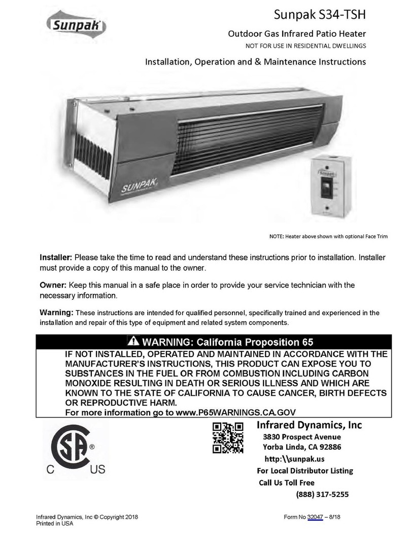
Sunpak S34-TSH Manual

Sunpak

Sunpak S34-TSH Manual

Sunpak S34 Instruction Manual

Sunpak

Sunpak S34 Instruction Manual

Sunpak S34?TSR Manual

Sunpak

Sunpak S34?TSR Manual

Sunpak S25 Manual

Sunpak

Sunpak S25 Manual

Sunpak S34?TSR User manual

Sunpak

Sunpak S34?TSR User manual

Popular Patio Heater manuals by other brands

Blumfeldt 10028637 manual

Blumfeldt

Blumfeldt 10028637 manual

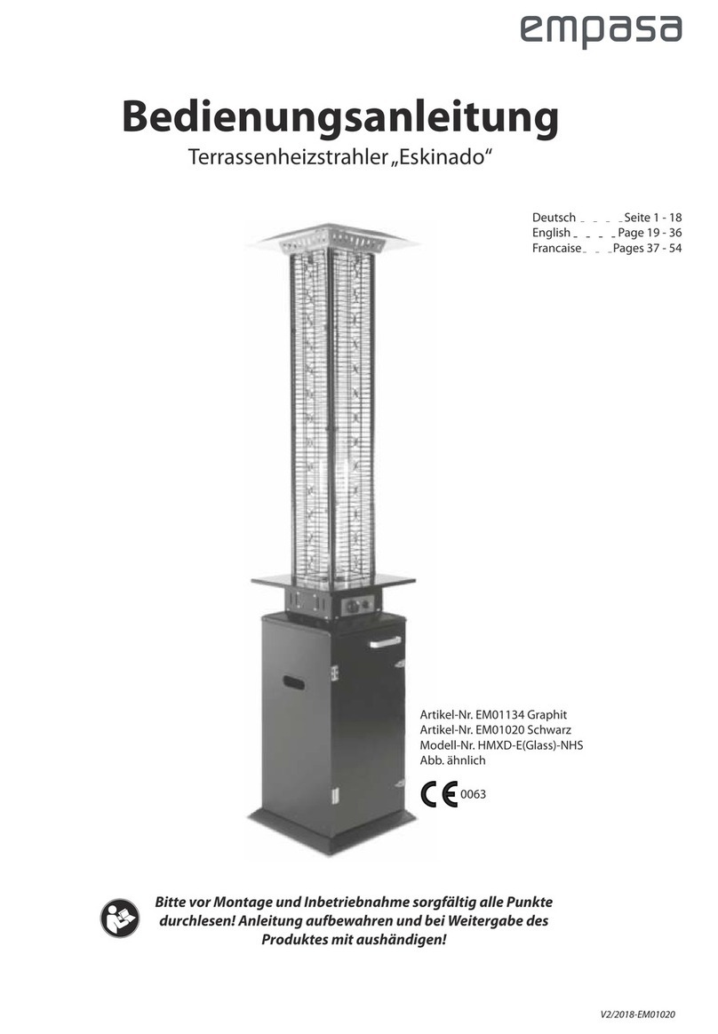
empasa HMXD-E-NHS operating instructions

empasa

empasa HMXD-E-NHS operating instructions

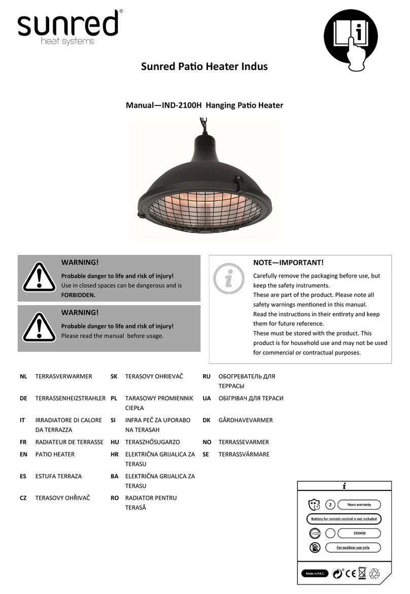
Sunred Indus manual

Sunred

Sunred Indus manual

HEAT1 ECO pro-line 2300W instructions

HEAT1

HEAT1 ECO pro-line 2300W instructions

Heatmaxx SRPH98 instruction manual

Heatmaxx

Heatmaxx SRPH98 instruction manual

Sunjoy L-PH011PSS-2 owner's manual

Sunjoy

Sunjoy L-PH011PSS-2 owner's manual

Sunjoy A30600640 manual

Sunjoy

Sunjoy A30600640 manual

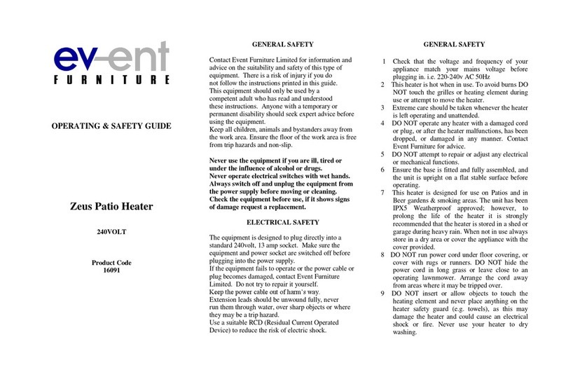
Event Furniture 16091 Operating & safety guide

Event Furniture

Event Furniture 16091 Operating & safety guide

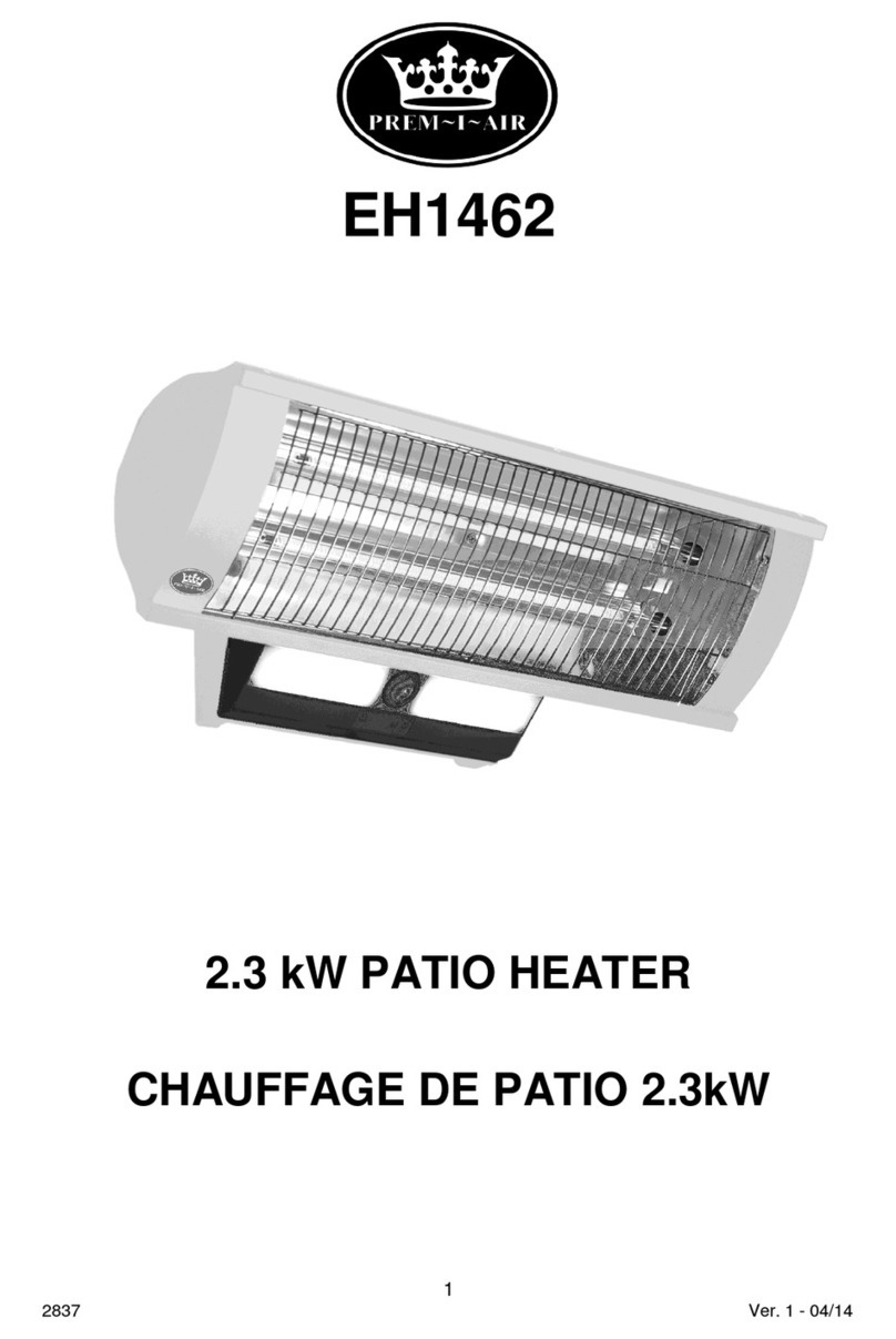
Prem-I-Air EH1462 manual

Prem-I-Air

Prem-I-Air EH1462 manual

Melissa 670-202 user guide

Melissa

Melissa 670-202 user guide

EHS Ltd. HQH-2000W instruction manual

EHS Ltd.

EHS Ltd. HQH-2000W instruction manual

VONROC ALICUDI PH515AC Original instructions

VONROC

VONROC ALICUDI PH515AC Original instructions

OZONA Heatflow IF010997 Safety instructions and operation manual

OZONA

OZONA Heatflow IF010997 Safety instructions and operation manual

theBBQshop 51611010 Safety, Installation, Operation and Maintenance

theBBQshop

theBBQshop 51611010 Safety, Installation, Operation and Maintenance

Matrix PV009-200KB Safety instructions and operation manual

Matrix

Matrix PV009-200KB Safety instructions and operation manual

DCS PHFS-P4 Use and care and installation guide

DCS

DCS PHFS-P4 Use and care and installation guide

Blumfeldt Hitzkopf manual

Blumfeldt

Blumfeldt Hitzkopf manual

Nexgrill 920-0049 Installation instructions and owner's manuals

Nexgrill

Nexgrill 920-0049 Installation instructions and owner's manuals

manuals.online logo
manuals.online logoBrands
  • About & Mission
  • Contact us
  • Privacy Policy
  • Terms and Conditions

Copyright 2025 Manuals.Online. All Rights Reserved.

Infrared Dynamics, Inc © Copyright 2012 Form No 60043 – 7/12
Printed in USA

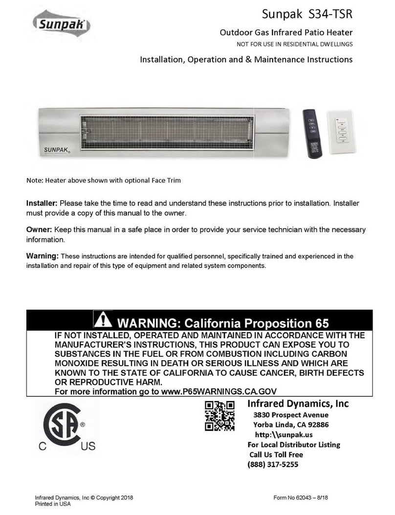
SunpakS34‐TSR
OutdoorGasInfraredPatioHeater
Installation,Operationand&MaintenanceInstructions


Installer: Please take the time to read and understand these instructions prior to installation. Installer
must provide a copy of this manual to the owner.
Owner: Keep this manual in a safe place in order to provide your service technician with the
necessary information.
Warning: These instructions are intended for qualified personnel, specifically trained and experienced in the
installation and repair of this type of equipment and related system components.
ForAssistanceCallTollFree
(888)317‐5255


InfraredDynamics,Inc
3830ProspectAvenue
YorbaLinda,CA92886
http:\\sunpak.us
Sunpak® Infrared Heaters
2

Table of Contents
1. Warnings
2. Basic Operation
3. Heater Layout and Design
4. Installation / Service
5. Replacement Parts
6. Trouble Shooting Guide
7. Warranty
Sunpak heaters work like the sun
projecting radiant heat down to warm your
patio and guests. This heater was
designed for outdoor installation however
breezes will affect the heating efficiency
and severe weather conditions will cause
the safety system to shut down the
heater. For your safety you must read
and understand the following warnings
before continuing.
WARNING WARNING
Improper installation, adjustment, alteration,
service or maintenance can cause death,
injury or property damage. Read and
understand the installation, operating and
maintenance instructions thoroughly before
installing or servicing this equipment.
Storage of gasoline and other flammable
vapors and liquids in the vicinity of this or
any other appliance may result in fire or
explosion. DO NOT store or use gasoline
or other flammable vapors and liquids in
the vicinity of this or any other appliance.
Always maintain clearance to
combustibles as specified.
WARNING
Not for indoor residential use.
This heater is not approved for use in any
indoor residential application. This includes,
but is not limited to, attached garage,
solarium, living quarter, etc. Installation in
residential indoor space may result in death,
asphyxiation, serious injury, or property
damage.
For Your Safety
If you smell gas:
•Shut off gas to the appliance
•Extinguish any open flame
•DO NOT touch any electrical
switch
•Call your gas supplier. DO NOT
use any phone in your building.
•Follow the gas supplier’s
instructions.
•If you cannot reach your gas
supplier call the fire department


Sunpak® Infrared Heaters
3
BasicHeaterOperation
SunpakS34TSRisanoutdoorgas‐fired
infraredheaterwhichisoperatedwithawireless
remotecontrol.Theheatercanbeoperatedata
Highsettingwithaninputof34,000BTU/Hrorata
LOWsettingof25,000BTU/Hr.Eachheatercomes
withwirelessoperatingremotecontrolsthatare
pre‐programmedforthatheater.Thenumber
locatedonthelouveredendoftheheater
correspondstothenumberontheremotecontrol.
Shouldtheoriginalremotecontrolbecomelost,
additionalremotecontrolscanbepurchased.
Howevertheheaterwillneedtobere‐programmed
tothenewremotecontrol.
TheSunpakS34‐TSRshouldalwaysbestartedupandoperatedontheHImodeforthefirst5
minutestoallowtheheatertowarmup.StartinguptheheaterontheLOWmodebeforethe
heateriswarmedupmaycausetheheatertoshutdownprematurely.Tocorrectthissituation
presstheOFFbuttonfollowedbytheONbuttonandtheHIbutton.AlwaysPRESSthebuttonfor
atleast1secondtoallowpropertransmissionoftheremotesignal.
DeviceBatter
y

WallRemote2032ButtonType
Handheld21/23–12V

Sunpakheatershaveasparkignitionand
electronicflamesafetycontrol.Thepilotis
onlyONwhiletheheaterisoperating.Ifthe
flamesafetysensorfailstosenseflameatthe
pilot,theheaterswillshutdownandlockout.
Thismayhappenduetolowgaspressureora
gustywind.Shouldtheheaterlockoutyou
maybeabletohearafaintbeepingfromthe
heatercontrol.Torestarttheheater,first
presstheOFFbuttonbeforerestartingthe
heater.
Althoughtheheaterisdesignedforoutdoor
installationanduse,itisimportantthatthe
wirelessremotecontrol(s)beprotectedfrom
theweather.Shouldtheremotecontrol
becomewet,itmaybenecessarytoreplace
thecontrol.Keepcontroloutofreachof
children
Eachcontrolhasfourbuttons(ONOFFHI
LOW).Theremotecontrolsarepoweredby
batteries.Theremotecontrolhasan
approximate25footlineofsightrange.Weak
batteriescanlimittheeffectiverangeof
operation.
Sunpak® Infrared Heaters
4
Heater Layout and Design
Sunpak®heaters were specifically designed to provide
heated comfort in an outdoor environment. They have been
used on outdoor patios across the United States and Canada
for over 20 years. When properly integrated into a patio
design, Sunpak®heaters generally increase the comfort level
5 to 10 degrees Fahrenheit outdoors. The heating
effectiveness will depend on air temperature, wind velocity
and other factors. Whenever possible other local Sunpak®
installations should be reviewed to determine the
effectiveness for regional environments.
The environments in which Sunpak®heaters are utilized
vary greatly. As an outdoor rated heater it has passed basic
wind and rain tests. This does not mean the heater cannot be
damaged by the environment or when operated in very windy
conditions. For this reason it is strongly suggested that
heaters be inspected and if necessary repaired annually or
before each heating season.
The variable environments in which Sunpak®heaters are
applied means that these general guidelines are generated by
necessity and may need to be refined for local conditions.
These guidelines are to be used in combination with the
installation instructions.

Patio Design Consideration
Heater placement is critical for effective and efficient
patio heating. If heaters are placed too close together or
mounted too low, people become uncomfortable. If heaters
are placed too far apart on a breezy, wind-swept patio the
patio may never get warm.
Sunpak® heaters work best if they are placed in areas of
the greatest heat loss, such as the open side of a semi-
protected patio area. The Sunpak® heater may be mounted
at up to a 30 degree angle or face down. Note that the top
clearances required from combustible material increases
when heaters are at any angle. The heater must always be
horizontal to the floor. Never mount the heater in the
vertical position.
Breezy conditions must be considered when heating
any patio. Windbreaks can be extremely effective in
increasing comfort and reducing heating costs.
Windbreaks must be designed in such a way to allow for
the necessary fresh air and ventilation for proper heater
operation (see ventilation of installation section).
Sunpak heaters must always be operated in a location
that allows uniform air pressure around the heater. If only
part of the heater is located in a wind protected zone
damage to the heater may occur. Time should be taken to
observe how the wind will affect the heaters under local
conditions.
MINIMUM CLEARANCE FROM COMBUSTIBLE MUST BE MAINTAINED (see chart on page 6 & 7) 


SUNPAK will raise the comfort level 5-10º Fahrenheit
outdoors. The above coverage table was based on still
breeze conditions. Under windy conditions more heat will
be required. It is recommended that a windswept patio be
designed with wind breaks to stabilize the patio
environment. Wind breaks shall NOT interfere with the
ventilation or combustion air requirements of the heater(s)
and meet clearance for combustible requirements listing
on page 6 & 7.
ANGLE MOUNTING: Most applications of the
SUNPAK heater may be angle-mounted to a
maximum of 30º to accommodate mounting the
heaters around the edges of the patio. Note that the
top clearance to combustibles increases when
heater is tipped from the horizontal.
NOTE: Local codes may have special requirements
regarding head clearance requirements. Some local
codes require all portions of overhead radiant
heaters to be located at least 8 feet above the floor.
Sunpak® Infrared Heaters
5

Sunpak® Infrared Heaters
6


Warning:Heatermustbelevelinthelengthwisedirection.

Sunpak® Infrared Heaters
7
Installation/Service Instruction
Receiving Equipment
On receipt of equipment it is suggested that a visual
inspection be made for external damage to the carton. If
the carton is damaged, a note should be made on the Bill
of Lading when signing for the equipment. Remove the
heater from the carton. If there is damage, report the
damage to the carrier immediately.
INSTALLATION INSTRUCTIONS
Important Notice
These instructions are intended for qualified personnel,
specifically trained and experienced in the installation of
this type of equipment and related system components.
Some states or provinces require installation and service
personnel to be licensed. If your state or province is
such, be sure your contractor bears the appropriate
license. Persons not qualified shall not attempt to fix this
equipment nor attempt repairs.
WARNING
Asphyxia, Explosion or Fire
Improper installation, adjustment,
alteration, service or maintenance may
create a hazard resulting in asphyxiation,
explosion or fire, or damage to the
equipment.
Code Requirements
Installation must be in accordance with local codes, or in
the absence of local codes, with the latest edition of the
National Fuel Gas Code, ANSI Z224 and National
Electrical Code ANSI/NFPA 70, and for Canada, the
latest edition of CAN/CGA-B149.1 and B149.2 and
Canadian Electrical Code, CSA C22.1 Part 1 and Part 2.
•Heaters to be installed in Aircraft hangars must be
installed in accordance with American National
Standards for Aircraft Hangars, ANSI/NFPA
No. 409.
•Heaters to be installed in Public Garages must be
installed in accordance with NFPA No. 88A,
Standards for Parking Structures.
•Heaters must be installed so that minimum
clearances marked on the heaters will be
maintained from vehicles parked below the heater.
•Each heater must be electrically grounded in
accordance with the National Electrical Code,
ANSI/NFPA 70, when an external electrical source
is utilized. In Canada, the CSA Canadian Electrical
Code, C22.1 Part 1 applies.
Gas Supply
The gas inlet supply pressure and manifold pressure required for
each heater are listed below. For gas supply line pressures in
excess of ½ psig, consult with your gas service provider or the
factory.
Gas Inlet Pressure Nat Gas Propane
Maximum Pressure ½ psig ½ psig
Minimum Pressure 6” W.C. 11” W.C.
Manifold Pressure 5” W.C. 10” W.C.
It is critical that the gas piping system be adequately sized
for all the gas appliances it serves.
Clearances
Each heater must be installed such that the following
“Minimum Clearance to Combustible Materials’ are maintained.
Combustible materials include wood, compressed paper, plant
fibers, plastic, Plexiglas or other materials capable of being
ignited and burned. Such materials shall be considered
combustible even though flame-proofed, fire retardant treated or
plastered. Additional clearance may be required for glass,
painted surfaces, vinyl siding or other materials which may be
damaged by radiant or convection heat.
Adequate space around each heater is required even when the
materials surrounding the heater are non- combustible to provide
adequate combustion air and ventilation of exhaust gases.
Heaters should never be located in a ceiling recess or soffit.
The stated clearance to combustible materials represents a
surface temperature of 90ºF (32ºC) above room temperature.
Building materials with a low heat tolerance (such as plastic, vinyl
siding, canvas, tri-ply, etc.) may be subject to degradation at
lower temperatures. It is the installer’s responsibility to assure
that adjacent materials are not subject to degradation.
In locations used for storage of combustible materials, signs
shall be posted to specify the maximum permissible stacking
height to maintain required clearances from the heater to
combustible materials.
OPTIONAL MOUNTING KIT (#12006): Optional Mounting Kit is
included in some packages. Whether the mounting kit is used or
not, minimum clearance from combustibles must be observed as
follows:
WARNING: The clearances shown below are also applicable to
vehicles parked below heaters.
Input Side Rear Ceiling Below Mtg.
Model BTUH In In In In Angle
S34 34,000 24” 17” 13” 48” HORIZ
S34 34,000 24” 8” 18” 48” 30º
MAX
Sunpak® Infrared Heaters
8

WARNING
Suspension Hazard
Mounting kits and hanging supports must
be able to withstand a minimum working
load of 75 lbs (33 kg). Failure of the
supports can result in death.
Local codes regarding head clearance
requirement must be observed.
Heater Mounting and Support
Heaters shall be mounted in a fixed position independent
of gas and electrical supply line. Hangers and brackets
shall be of noncombustible material.
Heaters subject to vibration shall be provided with
vibration isolating hangers.
Suitable materials for hanging infrared heaters are steel
pipe, steel channel, or fabricated hangers of at least 16-
gage material. Hanger and brackets must be secured with
adequate anchor to a secure structure using good
building practices. Additional bracing to protect against
seismic forces may be required in seismically active
areas. Never mount heater to a moving object such as a
trailer, motor home boat, etc.
Gas Piping
1. A minimum pipe size of ½” is required for inlet piping. A
½” leaver handled shut-off gas cock should be installed
within 6 feet of the appliance for servicing and as
emergency shutoff to the unit.
2. Check with local and state plumbing and heating codes
regarding sizing of gas lines.
3. All gas pipe connections to the heater(s) must be sealed
with a gas pipe compound resistant to liquefied
petroleum gases.
4. Installation of a drip leg or sediment trap in the gas
supply line going to each heater is required to minimize
the possibility of any loose scale or dirt within the gas
supply line from entering the heater’s control system.
5. When checking for gas leaks, do not use an open flame.
Use a soap and water solution.
6. For gas supply line pressures in excess of ½ psig,
consult the factory or your local representative.
7. Installation of 1/8” N.P.T. plugged tap accessible for test
gage connections is required upstream of the gas
supply connections to the heater.
8. Never use pipe sealing compound on brass to brass
flared fittings.
Electrical
1. The Power Adapter included provides 7.5 VDC to the
heater. The Power Adapter has a 24 inch wire lead
connected to the main heater module by two slide
connectors (see page 10). The low voltage connection
can be extended using 18 GA outdoor rated thermostat
wire up to 50 feet. For distances greater than 50 feet 16
GA or larger wire will be necessary.
2. If any of the original wire supplied inside the appliance
must be replaced, it must be replaced with wiring material
having a temperature rating of at least 105 degrees
Centigrade.
Sunpak® Infrared Heaters
9
Ventilation
1. It is required that areas above the heater be
properly vented to allow for necessary
combustion air and removal of combustion gases.
2. Heaters shall be provided with natural or
mechanical means to supply and exhaust at least
4 cfm per 1,000 BTU per hour of heater input.
Exhaust opening for removing the flue products
shall be above the level of the heaters.
3. Heater ventilation must comply with state and
local codes. Never use heater in enclosed area.
Fire Sprinklers
Fire Sprinklers must be located at an appropriate
distance from each heater to avoid accidental activation
of the sprinkler. Ethylene glycol or propylene glycol must
never be used in fire sprinkler systems where heaters are
present as these substances may become flammable
when heated. A fire sprinkler professional must be
consulted when heaters are installed where fire sprinklers
are present to insure that heaters and the fire sprinkler
system are properly integrated. Specific guidelines can be
found in NFPA 13 regarding design and specifications for
Fire Sprinkler Systems near heaters.

Initial Start-Up Procedure
(Read entire Procedure First)
1. Before turning ON your new heater make sure:
a. Heater is securely mounted and clearances from
combustible materials have been observed (see
Clearances – page 7);
b. Tip angle of heater does not exceed 30 degrees
(see Correct Mounting – page 12);
c. Gas line is properly connected and there are no
leaks (see Gas Piping – page 8);
d. Power adapter (7.5 VDC) is connected to a live
power outlet and connected properly to the
heater (see Electrical – page 8 and Basic Wiring
– page 10)
2. Start Heater;
a. Turn ON manual gas valve..
b. Genially press the ON button of the remote
control for 1 second;
c. Allow heater 5 minutes to full warm up. (in full
daylight it may be difficult to see the flame);
d. If heater locks out, press the OFF Button to
RESET Heater and repeat start up sequence.
e. If the heater locks out several times there may
still be air in the gas line.
NOTE: Some white smoke may appear
during or just after the initial start-up of the
heater. White smoke will dissipate with
proceeding use. This is normal due to
some residual lubricate on a new heater
Regular Service and Maintenance
Overtime,particularlyduringlongperiodsofnon‐use,
theheatercanaccumulatedirtanddebrisinand
aroundthepilotandtheburner.Routinemaintenance
shouldbeperformedatleastonceayearbyaqualified
serviceagencytoinsuretheheaterisoperating
properly.Morefrequentservicemayberequiredfor
heaterslocatednearwaterfronts.Iflocalserviceisnot
availablecallyournaturalgasorpropanesupplier.
Battery Life
Boththewallcontrolandhandheldremotesuse
batteriesavailableatthelocalhardwarestore.Please
keepinmindthefollowing:
•Weak batteries can reduce the range of the
transmitter.
•Batteries should be removed if heaters are not to
be used for a long period of time.
•Dispose of used batteries properly.
•Replace batteries annually or as needed.
Two #2032 Button Batteries power the wall control transmitter They
are available at your local hardware store.
Loss of Programming
Although each heater comes pre-programmed for two
devices, this programming can be lost if the following
occurs:
•ElectricalPowerSurge
•Heaterisdisconnectedalongperiodoftime.
•Morethanthreedeviceshavebeenprogrammedfor
theheater.
Sunpak® Infrared Heaters
10

YoumustremovetheSunpakFaceTrimtoconnectpowertotheheater.TheSunpakFaceTrimissecuredwith
four(4)screws,two(2)locatedalongeachsideoftheheater.


BasicWiring
SunpakS34‐TSRrequires7.5VDCforitscontrols.Inmostcasesyouwill
berunninglowvoltagewirefromthePowerAdapterpluggedintoa120
VACoutlet.ThePowerAdapterisnotwaterproofandmustbeweather
protected.Theextensionwirecanberun50feetwith18GAandmust
havesuitableoutdoorinsulation.Inordertoaddtheextensionwireyou
must:
1. RemovetheFaceTrim
2. DisconnectthePowerAdapterfromthecontrolmodule.
3. Attachtheslideconnectortotheextensionwire.
4. Connectoneendoftheextensionwirecabletothemoduleand
theotherendtothePowerAdapter
WARNING:DonotattachtheExtensionCabledirectlytothe120VAC
Outlet.
NOTE:MaleandFemaleconnectionsaresuppliedintheextensionkit
suppliedwitheachheater