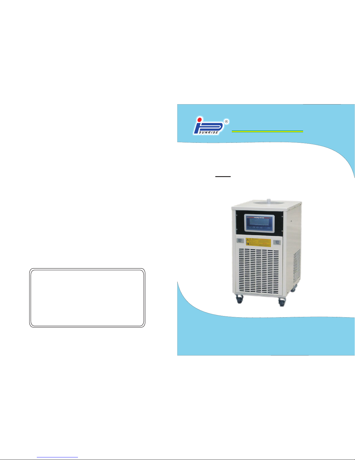
LAS ER C HI LLER OP ER AT ORS MAN UA L LAS ER C HI LLER OP ER AT ORS MAN UA L LAS ER C HI LLER OP ER AT ORS MAN UA L
712
Warning: please cut off the power before installation!!
3.2 Site requirements:
Ambient temperature and relative humidity (RH)
Our chiller suitable for install indoors, ambient temp. from 5℃ to 35℃, RH
less than 80%(No condensation) .
Location
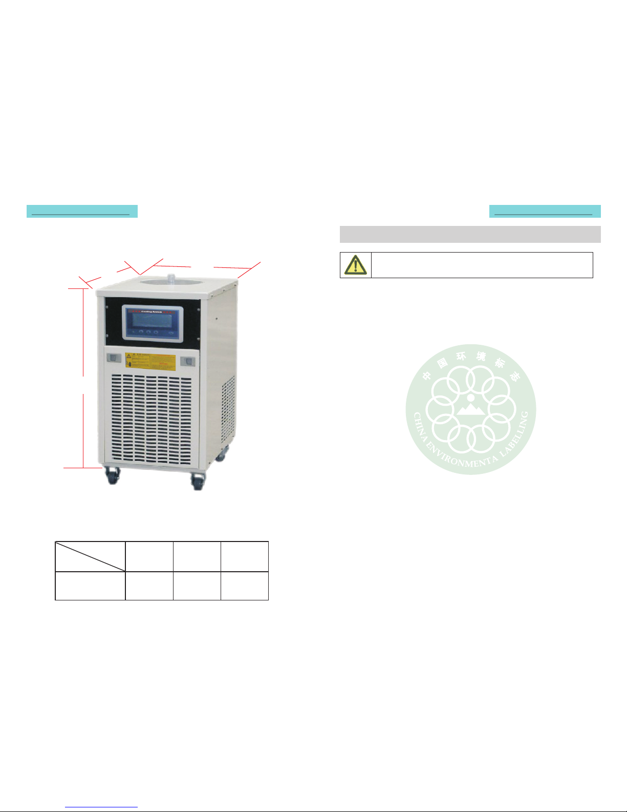
The chiller should be installed on solid horizontal surface, the closer to the
laser equipment, the better cooling performance will achieve; keep the
chiller off the heating source at least 4inch (1.4meters), such as heating tube
and boiler.
Please install the chiller at place where drainage system is available in order to
keep the installation place clean in case of any leakage occurs, please don't
install the chiller in erosive gas, humidity, dusty places or indoors with high
temp..
Our chiller is equipped with wheel, which makes it easier for installation and
operation; the front wheel could be locked to secure the unit. Avoid
voltage drops by using properly grounded power outlets wired with 14 gauges
or larger diameter wire. If possible, be close to the power distribution panel.
Using an extension cord may cause low line voltage problems, the voltage
loss should be with 10 % from the extension cord if this is inevitable.
The heating discharged by the fan is 1.4 times than the rated cooling capacity,
so the air- draft and air discharge side shouldn't be too close to wall. The air
discharge side should reserve at least 0.8m, the installation site should
ventilate well, the air-draft and air discharge volume of the site should be
a bit large than the chiller, or use air-condition with larger cooling
capacity than the heat discharge of the chiller to cool the installation site.
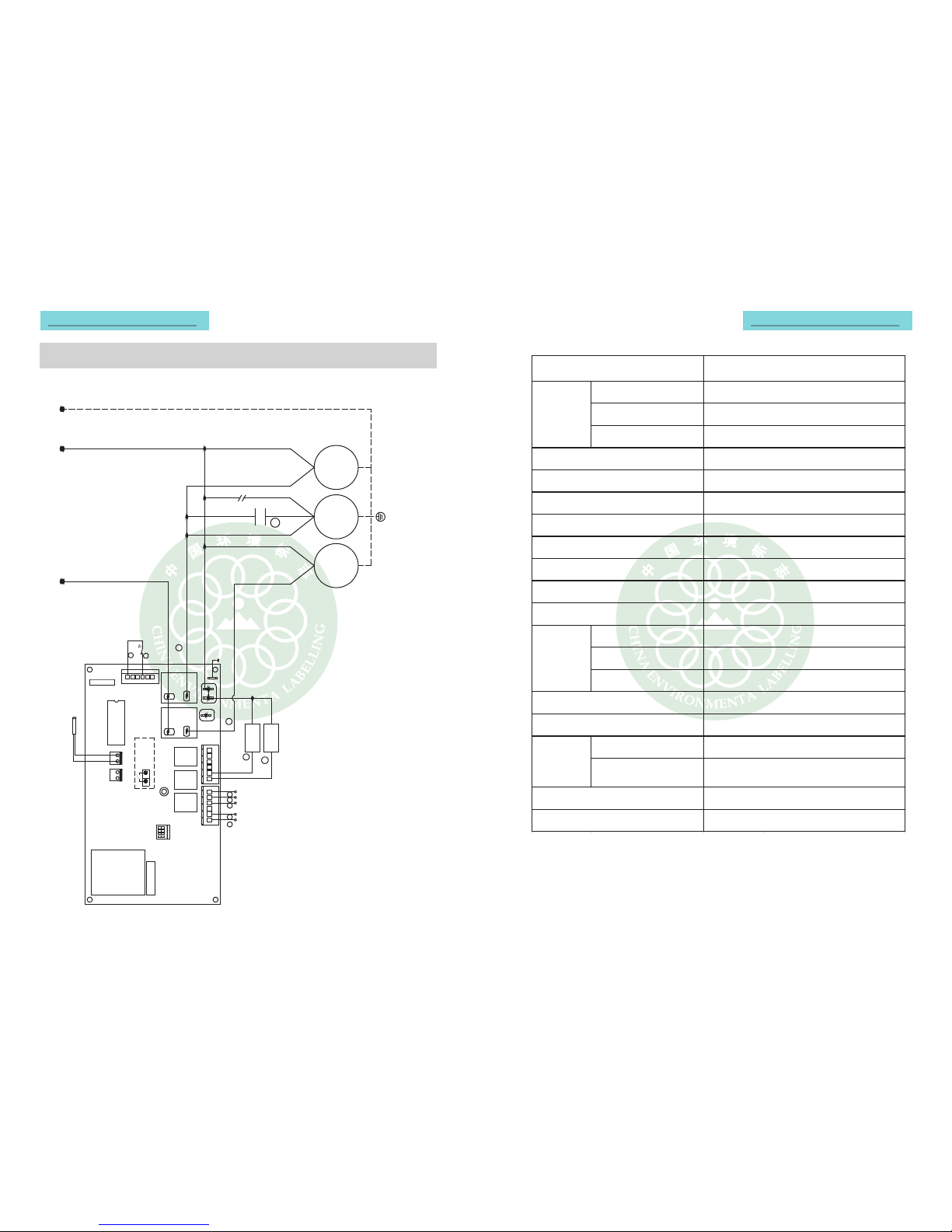
3.3 Power connection
Make sure the power wire rightly connected and current, frequency should be
match with the requirements marked on the label which was pasted on the back
of the chiller.
3.4 Connection accessories
Process pipeline
There are 2 inner thread interfaces for water pipe connection and water inlet
and outlet adapter is designed for connecting the accessories and working
pipeline.
In order to keep the working site clean and safe, please choose the right flexible
tube and accessories based on the liquid temperature and required temp.
Version information
4.3 Load factory default setting
4.4 Software version
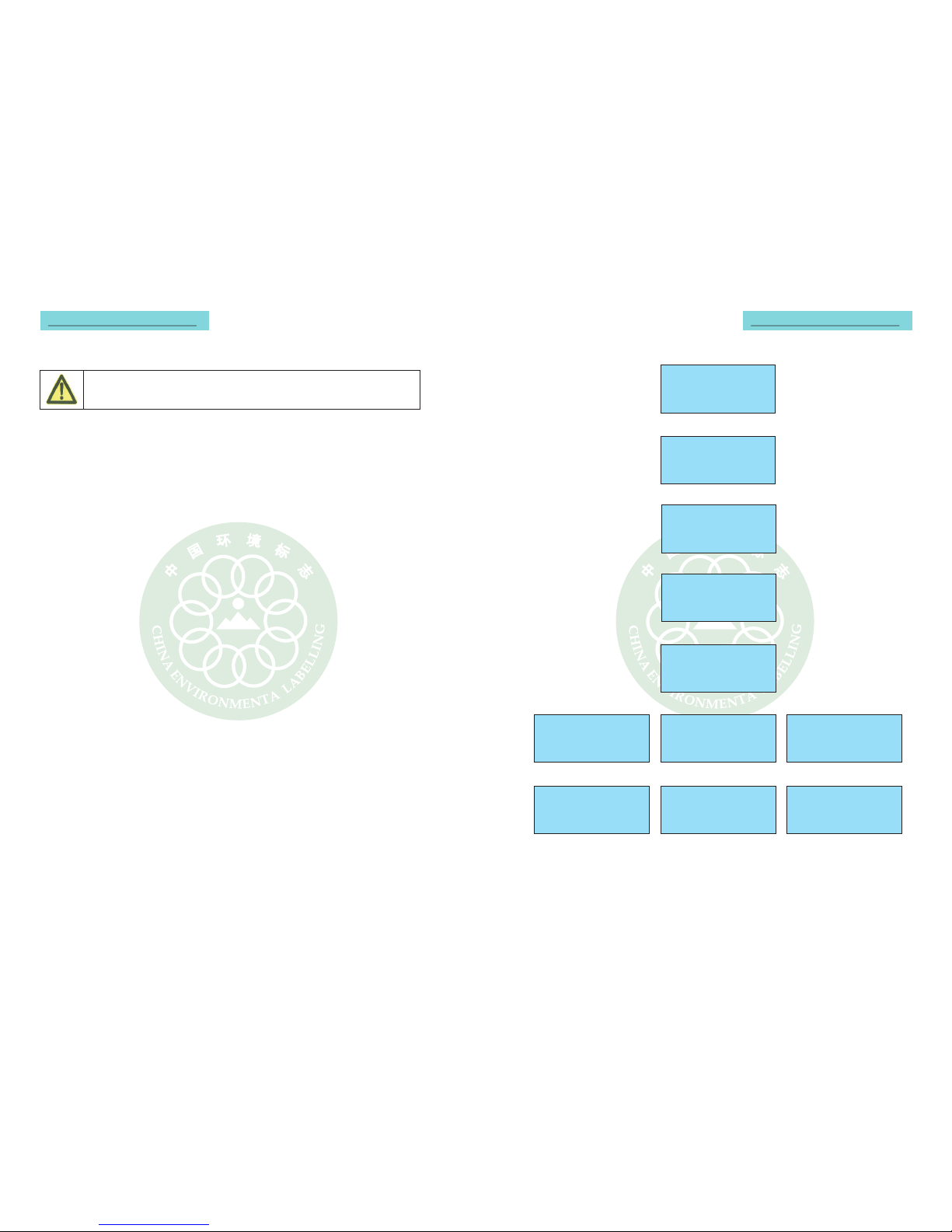
5 Alarm prompt, the LCD screen flashes when alarming,on & off every 1sec
DLY-619-V1.0-XX
Startup mode
Whet her aut omatical ly
startup when pow er on X
4.2.6 startup option, press up and down button to choose "yes" or "no"
System function view
cooling only (bypass)
Factory default setting
Please confirm to load factory
default setting?
Yes: kee p press ing set button for 5se c
No: press power button to exit
Phase reversal alarm
Change any two of three
live wires after power cut
off, please trouble shoot
and restart the system.
Liquid level alarm
Low liquid leve l or liquid leve l sw itch
mal func tion, fill more water or repl ace
liquid leve l sw itch; press ret urn/ pow er
butt on to rel ease al arm .
!High temp. alarm!
Water temp . exceeds the ma x.
setting va lue, fill cooling wa ter or
stop the system. pr ess return/power
button to release al arm.
Overload alarm!
Wire error or heavy load, please
let professional troubleshoot!
press return/power button to
release alarm.
Pressure alarm!
Refrigerating system leakage,
track down the leakage point and
recharge refrigerant. press return
/power button to release alarm.
Low temp. alarm!
Water temp. lower than min setting
value. Fill normal temp. water or
stop system! Press return/power
button to release alarm.
Water flow alarm!
Low wa ter flow or flow switch, wa ter
pump breakdown please check
water ci rcuit or replace co mp onent!
Press return/power button to release
alarm.