1 General safety notes
■Read the operating instructions before commissioning.
■
Connection, mounting, and configuration may only be performed by trained
specialists.
■
Not a safety component in accordance with the EU Machinery Directive.
■
Do not install the sensor at locations that are exposed to direct sunlight
or other weather influences, unless this is expressly permitted in the operating
instructions.
■These operating instructions contain information required during the life cycle of
the sensor.
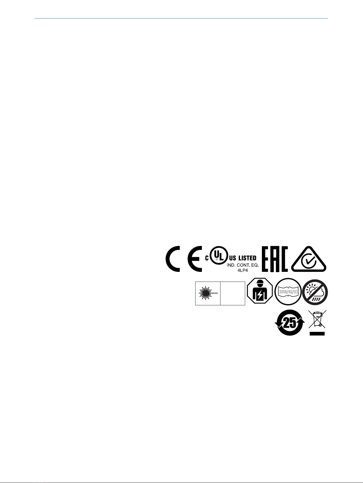
EN/IEC 60825-1:2014
IEC60825-1:2007
LASER CLASS 1
Laser
1
Maximum pulse power < 5.95 mW
Puls length: 2 µs
Wavelength: 670 - 690 nm
Complies with FDA performance
standards except for conformance with
IEC 60825-1 Ed. 3,
as described in Laser Notice No. 56,
dated May 8, 2019
ATTENTION
WARNING: Interruption, manipulation or incorrect use can lead to hazardous exposure
due to laser radiation.
2 Notes on UL approval
The device shall be supplied from an isolating transformer having a secondary overcur‐
rent protective device that complies with UL 248 to be installed in the field rated either:
a) max 5 amps for voltages 0 ~ 20 V (0 ~ 28.3 V peak), or
b) 100 / Vp for voltages of 20 ~ 30 V (28.3 ~ 42.4 V peak).
Alternatively, they can be supplied from a Class 2 power supply.
UL Environmental Rating: Enclosure type 1
3 Intended use
The GTB6L is an opto-electronic photoelectric proximity sensor (referred to as “sensor”
in the following) for the optical, non-contact detection of objects. If the product is used
for any other purpose or modified in any way, any warranty claim against SICK AG shall
become void.
GENERAL SAFETY NOTES 1
8025391.1AR6 / 21.02.2021 | SICK
Subject to change without notice 5