Super Gym SG8018MT User manual

SG8018MT Leg Extension
Assembly Instructions

Table of contents
Important Safety Instructions-------------------------------------------------------- 1
Exploded View Diagram---------------------------------------------------------------- 2
Hardware List----------------------------------------------------------------------------- 3
Parts List----------------------------------------------------------------------------------- 5
Assembly instructions----------------------------------------------------------------- 6

1
Important Safety Instructions
Before beginning any fitness program, you should obtain a complete
physical examination from your physician. When using exercise equipment,
basic precautions should always be taken, including the following:
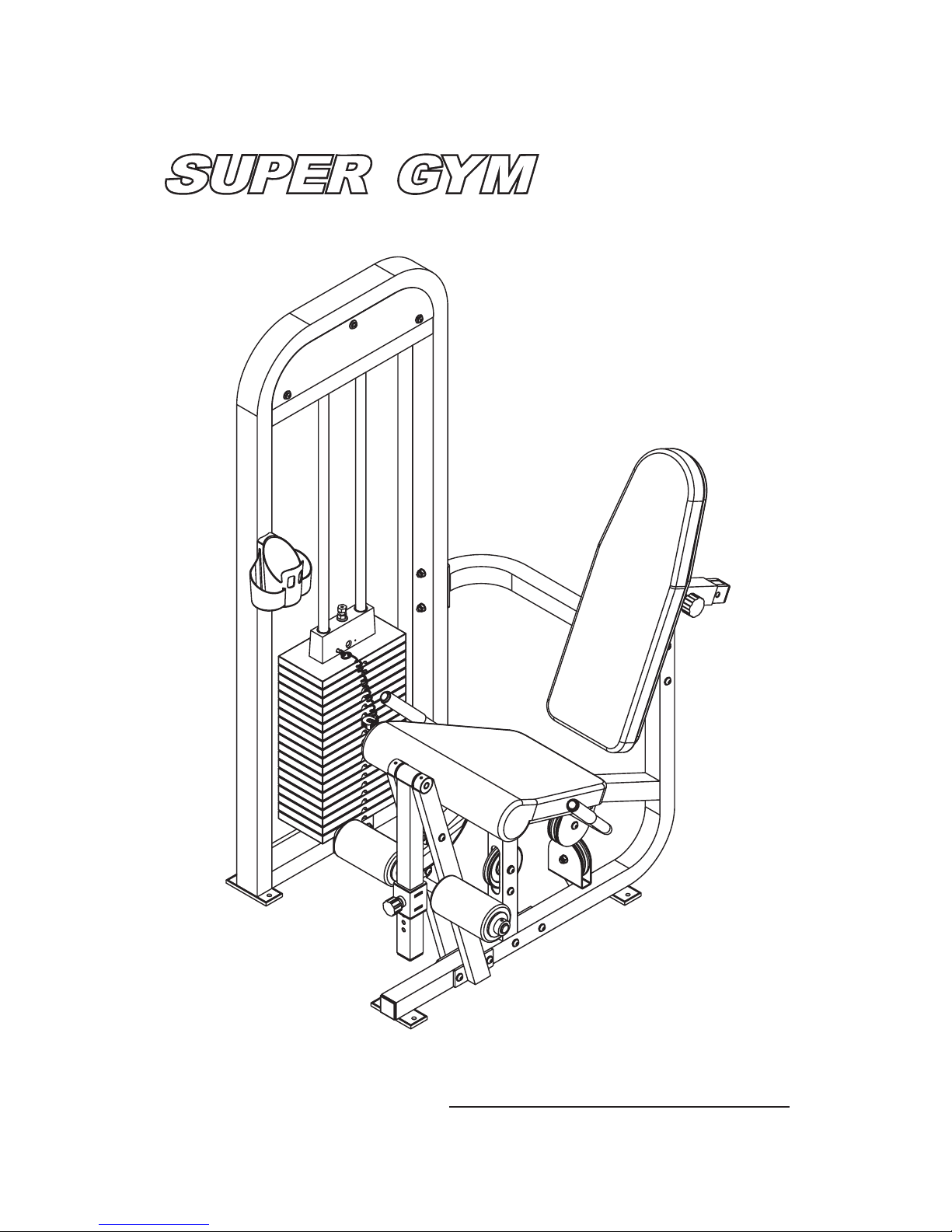
* Read all instructions before using the Leg Extension. These instructions
are written to ensure your safety and to protect the unit.
* Do not allow children on or near the equipment.
* Use the equipment only for its intended purpose as described in this guide.
Do not use accessory attachments that are not recommended by the
manufacturer: such attachments might cause injuries.
* Wear proper exercise clothing and shoes for your workout----no loose
clothing.
* Be careful when getting on or off the equipment.
* Do not overexert yourself or work to exhaustion.
* If you feel any pain or abnormal symptoms, stop your workout immediately
and consult your physician.
* Never operate the unit when it has been dropped or damaged.
* Never drop or insert anything into any opening in the equipment.
* Always check the unit and its cables before each use. Make sure that all
fasteners and cables are secure and in good working condition.
* Frayed or worn cables can be dangerous and may cause injury.
Periodically check these cables for any indication of wear.
* Keep hands, limbs, loose clothing and long hair well out of the way of
moving parts.
* Do not attempt to lift more weight than you can control safely.
* Do not use the equipment outdoors.
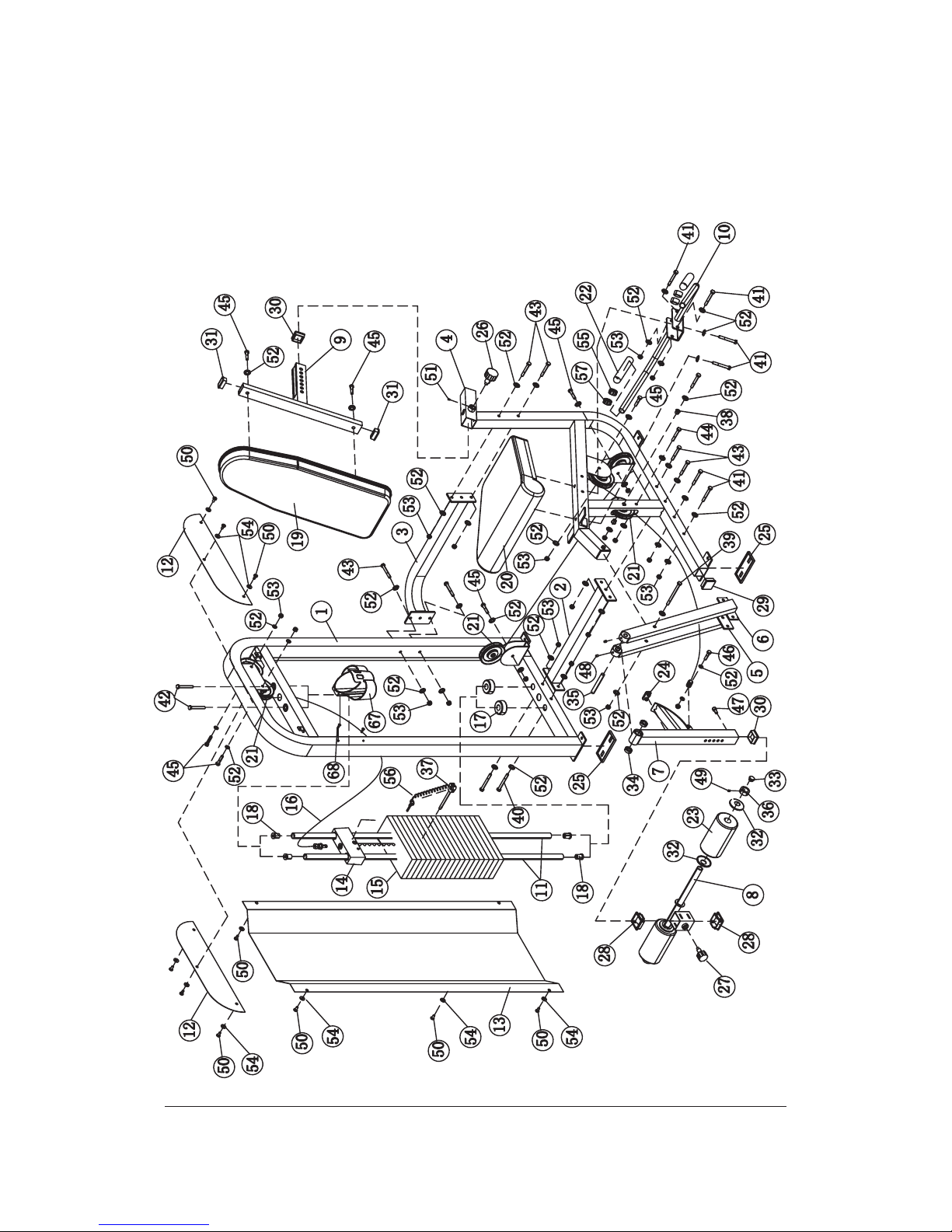
* Read each step in the assembly instructions and follow the steps in
sequence. Do not skip ahead. If you skip ahead, you may learn later that
you have to disassemble and that you may have damaged
the equipment.
* Assemble and operate the equipment on a solid, level surface. Locate the
unit a few feet from walls or furniture to provide easy access. The Leg
Extension is designed for your enjoyment. By following these precautions
and using common sense, you will have many safe and pleasurable hours
of healthful exercise with the equipment.
Personal Safety During Assembly
comportments

Leg Extension
Exploded View Diagram
2

Hardware List
3

Hardware List
4

5
Parts List
Item No. Description QTY Item No. Description QTY
1 Main Upright 1 32 Plastic Washer 4
2 Low Cross Brace 1 33 Plug φ25 2
3 Upper Cross Brace 1 34 Bearing 2
4 Seat Frame 1 35 Leg Extension Pivot 1
5 Right Support Tube 1 36 Collar 2
6 Left Support Tube 1 37 Weight Pin 1
7 Swivel Frame 1 38 Pulley Spacer 2
8 Slide Roller Pad Frame 1 39 Allen Bolt M10*130 1
9 Back Pad Support 1 40 Allen Bolt M10*95 2
10 Handle 1 41 Allen Bolt M10*80 6
11 Guide Rod 2 42 Bolt M10*72 2
12 Upper Shroud 2 43 Allen Bolt M10*75 7
13 Weight Shroud 1 44 Allen Bolt M10*65 1
14 Top Plate 1 45 Allen Bolt M10*50 7
15 Weight Plate 19 46 Allen Blot M10*40 1
16 Cable 1 47 Shoulder Bolt M10*20 1
17 Weight Stack Bumper 2 48 Allen Screw M8*12 2
18 Rubber Plug 4 49 Allen Screw M8*8 2
19 Back Pad 1 50 Allen Bolt M8*15 10
20 Seat Pad 1 51 Screw M4*5 1
21 4.5" Pulley 6 52 Washer φ10 46
22 Grip 2 53 Nylon Lock Nut M10 21
23 Roller Pad 2 54 Washer φ8 10
24 Bumper Pad 1 55 φ25 Cap ring 2
25 Foot Pad 4 56 Weight Pin Leash 1
26 Big Pop Pin 1 57 φ25 Cap 2
27 Small Pop Pin 1 58 Allen Wrench S=4 1
28 Slide Sleeve 2 60 Grease 1
29 Plug □50 1 62 Socket Wrench S=6 1
30 Plug □44.5 2 67 Bottle Holder 1
31 Plug □50*25 2 68 Philip Screw M6*15 2

Assembly Instructions
Assembly of takes professional installers about 2 hours. If
this is the first time you have assembled this type of equipment, plan to
spend more time. It is strongly recommended to assemble the equipment by
professional installers. You may find it quicker, safer, easier to assemble this
equipment with the help of a friend, as some of components may be large,
heavy or awkward to handle alone. It is important that you assemble your
product in a clean, clear, uncluttered area. This will enable you to move
around the product while you are fitting components and reduce the
possibility of injury during assembly.
As with any assembled part, proper alignment and adjustment is critical.
While tightening the fasteners, be sure to leave room for adjustments. Do
not fully tighten the fasteners until instructed to do so. Be careful to
assemble the components in the sequence presented in this guide.
the Leg Extension
6

Step1 Install the Sub-Support Component
1. Attach Low Cross Brace (#2) and Upper Cross Brace (#3) to Main Upright
(#1) using:
2. Attach Seat Frame (#4) to Low Cross Brace (#2) and Upper Cross Brace
(#3) using:
two Allen Bolts (#40) M10*95 two Allen Bolts (#43) M10*75
eight Washers (#52) four Nylon Lock nuts (#53) M10
four Allen Bolts (#43) M10*75 eight Washers(#52)
four Nylon Lock nuts(#53) M10
7

48
Step2 Assemble Leg Extension
1. Attach Right Support Tube (#5) and Left Support Tube (#6) to the Seat
Frame (#4) using:
2. Insert Leg Extension Pivot (#35) to Right Support Tube (#5) Swivel Frame
(#7) and Left Support Tube (#6) then secure them using:
two Allen Bolts (#41) M10*80 six Washers (#52)
three Nylon Locknuts(#53) M10 one Allen Bolt (#39) M10*130
two Allen Screw (#48) M8*12
8

Step3 Assemble Weight Stack
1. Insert both the Guide Rods(#11) into the Main Upright (#1).
2. Slide Weight Stack Bumper (#17) down onto each the Guide Rod(#11).
3. Carefully begin sliding the Weight Plate one by one in sequence: #15,#14
4. Align the both ends of Guide Rods(#11) to the Main Up-right and secure
them using:
5. Screw Weight Pin Leash (#56) to Top Plate (#14) and then clip to Weight
Pin(#37).
two Bolts (#42) M10*72
9

Step4 Route The Cable
1. Connect the looped end of Cable (#16) to the Bracket weld on the Swivel
Frame (#7) secure it using:
2. Pass Cable through the window of the Seat Frame (#4) and route under
the Pulley (#21) and secure to Seat Frame (#4) using:
Then attach one Bolt (#44) M10*65 two Dishing Washers (#52) one Nylon
Lock Nut (#53) to Seat Frame (#4) as a cable retainer.
3. Route the Cable over the Pulley and attach to pulley bracket weld on the
Seat Frame using:
one Allen Bolt(#46) M10*40 two Washers (#52)
one Nylon Locknut(#53) M10
one Allen Bolt (#43) M10*75 two Washers (#52)
one Nylon Lock Nuts (#53) two Pulley Spacers (#38)
one Allen Bolt (#45) M10*50 two Washers (#52)
one Nylon Lock Nut (#53)
10
Make sure the cable is between the Pulley and Allen Bolt (#44).

Step5 Route The Cable
11
1. Route the Cable under the Pulley and attach to pulley bracket weld on
the Seat Frame (#4) using:
2. Route the Cable under the Pulley and attach to pulley bracket weld on
the Main Upright (#1) using:
one Allen Bolt (#45) M10*50 two Washers (#52)
one Nylon Lock Nut(#53) M10
one Allen bolt (#45) M10*50 two Washers (#52)
one Nylon Lock Nut (#53)M10

1. Pass the Cable through the window of the Main Upright (#1) and route the
cable over the Pulley (#21) attach the long pulley bracket weld on the Main
Upright (#1) using :
The same way to attach another pulley .
2. Pass the Cable through the window of the Main Upright down to the selector
pin and screw the Cable end into the selector pin ,adjust the cable length by
the Allen bolt tighten the Allen bolt and selector pin together with a Jam Nut.
one Allen bolt (#45) M10*50 two Washers (#52)
one Nylon Lock Nut (#53) M10
12
Step6 Route The Cable

13
Step7 Assemble The Handle
1. Attach Handle (#10) to the Seat Frame (#4) using :
2. Attach Seat Pad (#20) to the Seat Frame (#4) using:
two Allen Bolts (#41) M10*80 four Washers (#52)
two Nylon Lock Nuts (#53) M10
two Allen Bolts (#41) M10*80 four Washers (#52)

Step8 Assemble Back Pads
1. Attach Back Pads (#19) to Back Pad Support (#9) using:
2. Insert the Back Pad Support (#9) into the Seat Frame (#1) and locate by
Big Pop Pin.
two Allen Bolts (#45) M10*50 two Washers (#52)
14

1. Align four Plastic Washers (#32) two Roller Pads (#23) to Slide Roller Frame
(#8) and then secure them using:
2. Put Slide Roller Frame (#8) onto the Swivel Frame (#7), locate it by small
Pop Pin (#27).
3. Screw a Shoulder Bolt (#47) to the Swivel Frame (#7) as a stopper.
4. Attach the Bottle Holder (#67)to Main Upright (#1)using:
two Collars(#36) two Allen Screws (49)
two Phillips Head Screw(#68) M6*15
Step9 Assemble Pads and Holder Bottle
15
Tighten all bolts and nuts used in Step1-Step9 by wrench.

1. Attach two Upper Shrouds (#12) to Main Upright (#1) using:
2. Attach Weight Shroud (#13) to Main Upright (#1) using:
six Allen Bolts (#50) M8*15 six Washers (#54) φ8
four Allen Bolts (#50) M8*15 four Washers (#54) φ8
Step10 Assemble Shroud
16
Table of contents
Other Super Gym Fitness Equipment manuals
Popular Fitness Equipment manuals by other brands

CAPITAL SPORTS
CAPITAL SPORTS 10032055 manual

Oregon Scientific
Oregon Scientific SZ999 user manual

Stairmaster
Stairmaster TwistLock Dumbbell owner's manual

ESCALADE
ESCALADE Mizerak 25120 Assembly instructions and rules

GymnaUniphy
GymnaUniphy Myo 200 user manual

Domyos
Domyos Domyos STEP 160 operating instructions

Crivit
Crivit 274628 Instructions for use

CAPITAL SPORTS
CAPITAL SPORTS Domic quick start guide

Energetics
Energetics MB 10 Assembly manual

Align-Pilates
Align-Pilates Wall Unit & Barre Bar installation instructions

Velocity Fitness
Velocity Fitness CHB-R6 instructions

Slendertone
Slendertone System+ instruction manual