Superior PBM-2500 User manual

SUPERIOR
PBM-2500
End Prep Machine
Operating Manual
Superior Plant Rentals, LLC.
NUMB
This document contains proprietary and condenal
informaon which is the property of Superior Plant Rentals
LLC (SPR). It is loaned for limited purposes only and
remains the property of SPR. Reproducon in whole or
part, use of the design, or distribuon of this informaon
to others is not permied without the express wrien
consent of SPR. This document is to be returned to SPR
upon request or upon compleon of the use for which it
was loaned. This document and the informaon contained
and represented herein are copyrighted property of SPR.
REV
SPR-MAN-PBM-2500 01
DOCUMENT NUMBER
CONFIDENTIALITY STATEMENT

SPR-MAN-PBM2500
sprentalsllc.com
PAGE ii
SUPERIOR
THIS PAGE INTENTIONALLY LEFT BLANK

SPR-MAN-PBM2500
sprentalsllc.com
PAGE iii
SUPERIOR
Superior Plant Rentals, LLC. (SPR) specializes in portable machining, bore welding, line
isolaon, and tesng soluons, providing equipment and tools manufactured under the
highest standards of quality control and engineering experse along with 24/7 service and
support. Designed with the operator in mind, our tools and equipment deliver dependable
and precise performance, providing cost-eecve soluons and reduced downme, making
them benecial resources in the Oil and Gas, Mining, Heavy Construcon, Shipbuilding, and
Power Generaon industries.
SPR rents and sells equipment and tools; we oer our own line of portable ID/OD ange
facers, linear/gantry and rotary mills, end prep bevelers, isolaon and test plugs, line
boring, and bore welders, as well as custom-designed equipment and tools.
Our team includes machining, test and isolaon, and engineering experts, all with a
thorough working knowledge of applicaons to support you with our equipment on any
job. We understand the urgency of your projects and are commied to delivering the
highest quality equipment and tools to sasfy the requirements of your clients.
SPR delivers outstanding customer service, specialized training by seasoned professionals,
and tools as tough as the jobs you need them to do.
ABOUT US
YORK
PORTABLE MACHINE TOOLS
SUPERIOR
PLANT RENTALS
CLIFF’S BITS
PRECISION GRINDING & TOOLING

SPR-MAN-PBM2500
sprentalsllc.com
PAGE iv
WARNING:
SPR is commied to connued product improvement; therefore, the machine you received may be slightly
dierent than the one described herein. This manual and the informaon provided is a basic guideline for
our customers. SPR will do its best to ensure that the informaon and procedures contained in this manual
are correct and up-to-date. Superior cannot guarantee that the informaon and procedures contained
herein are correct for all applicaons or situaons.
The contents of this manual are subject to change without noce. It is the obligaon of the user to read all
informaon in this manual, become familiar with the equipment to be used, and exercise the utmost care
in equipment operaon.
Do not operate this equipment if all parts
are not funconing at 100% eciency. Nofy us immediately for any needed repairs.
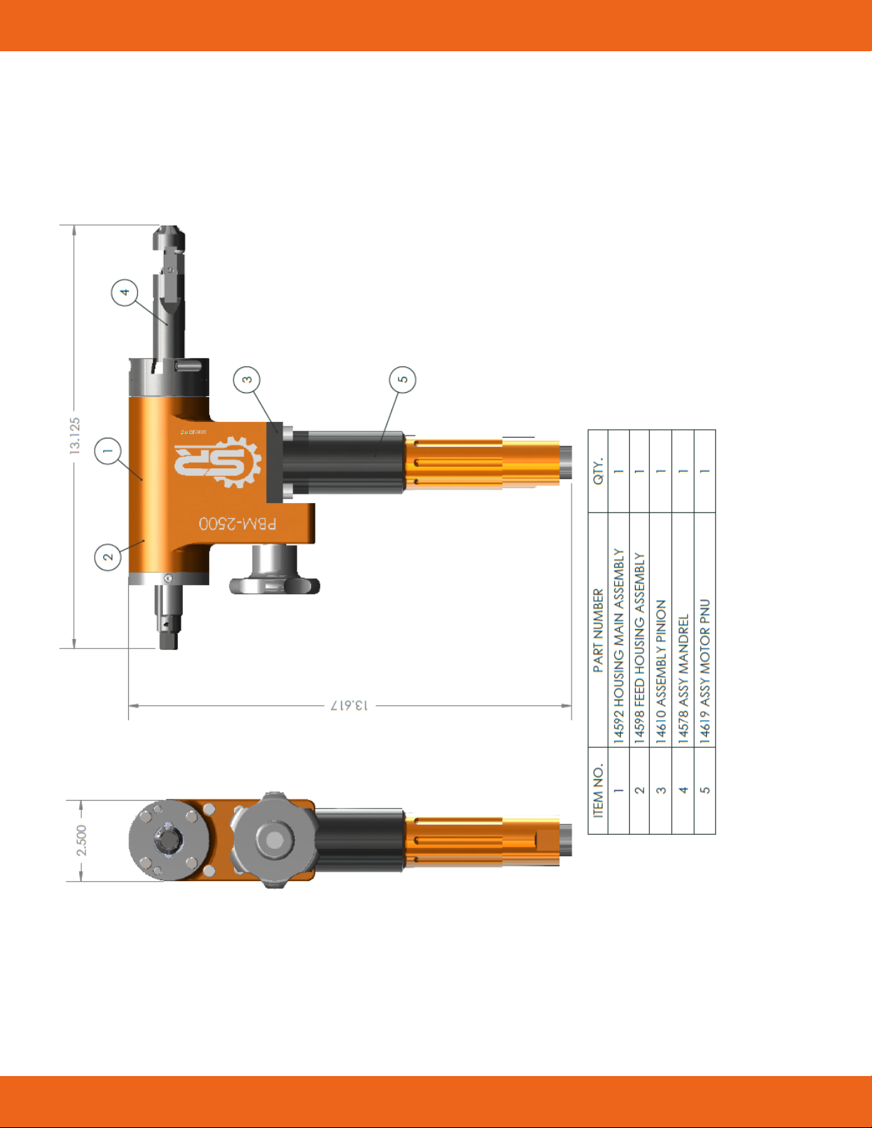
Note: SPR will supply all repair and replacement parts necessary for maintenance and operaon
of this machine. For repair, service, or addional informaon, please locate repair and
replacement part descripon/part numbers within the O&M manual in the exploded view secon
and contact us for ordering.
USA
Superior Plant Rentals LLC.
2910 S Ruby St. Gonzales, LA 70737 | Phone: 225.647.7771
Superior Plant Rentals LLC.
1530 Live Oak Webster, TX 77598 | Phone: 281.554.9400
Superior Plant Rentals LLC.
2160 Wellspring Drive, Beaumont TX 77705 | Phone: 409.853.4382
Superior Plant Rentals LLC.
8233 Leopard Street, Corpus Chris, TX 78409 | Phone: 361.541.5900
Superior Plant Rentals LLC.
2030 Gladwick St., Unit B, Rancho Dominguez, CA 70220 | Phone: 310.356.6105
INTERNATIONAL
York Portable Machine Tools
1641 17th Ave, Campbell River, BC, Canada, V9W 4L5 | Phone: 250.287.7716

SPR-MAN-PBM2500
sprentalsllc.com
PAGE v
1. INTRODUCTION.............................................................................................. 1
2. SPECIFICATIONS CHART ................................................................................. 2
3. SAFETY PRECAUTIONS ................................................................................... 3
4. STANDARD EQUIPMENT ................................................................................. 4
5. PRODUCT DESCRIPTION ................................................................................. 6
6. INITIAL SET-UP ............................................................................................... 7
7. SETTING AND SELECTING TOOL BITS ............................................................. 9
8. SETTING UP CLAMPING MANDRELS AND BLADES/SIZES ............................. 11
9. STARTING AND OPERATING THE MACHINE .................................................. 12
10. EXPLODED VIEWS......................................................................................... 14
11. MAINTENANCE ............................................................................................ 19
12. WARRANTY .................................................................................................. 20
TABLE OF CONTENTS PAGE

SPR-MAN-PBM2500
sprentalsllc.com
PAGE vi
SUPERIOR
THIS PAGE INTENTIONALLY LEFT BLANK

SPR-MAN-PBM2500
sprentalsllc.com
PAGE 1 OF 22
APPLICATIONS
The PBM-2500 machine is lightweight, just 13 lbs. and is designed to bevel boiler tubes and small pipe.
The tool bits are held in place by our wedge lock system. The clamping mandrel with bolt-on locator pads
(no springs) stops any pieces from dropping down into the work piece. Our gear drive unit has spiral bevel
gears for backlash free moon and more teeth engagement.
When you receive the PBM-2500:
Inspect the machine for shipping damage. Verify that all of the parts listed below, or on the Bill
of Materials, are present. If any parts are missing, or if you have quesons regarding the PBM-
2500, please contact a Superior Plant Rentals or York Portable Machine Tools locaon nearest you.
immediately.
INTRODUCTION
13.13
13.63
2413
5
2.5
ITEM NO.
PART NUMBER
QTY.
1
PBM-2102 FEED HOUSING ASSEMBLY
1
2
PBM-2100 MAIN HOUSING ASSEMBLY
1
3
TOOL BIT
1
4
PBM-2101 MANDREL ASSEMBLY
1
5
13660 MOTOR AIR 1.1HP-280RPM-.5IN
1

SPR-MAN-PBM2500
sprentalsllc.com
PAGE 2 OF 22
SPECIFICATIONS CHART
2500
ID Mounng Range: Small Mandrel (Oponal) 0.500 in - 1.250 in (12.7 mm - 31.8mm)
Standard Mandrel 1.000in - 2.500 in (25.4 mm – 63.5 mm)
Large Mandrel (Oponal) 2.500 in – 4.000 in (63.5mm – 101.6mm)
Cung Range 0.500in - 4.000in (12.7 mm – 101.6 mm)
Radial Clearance 2.500in (63.5 mm)
Max Wall Thickness 0.625 in
Oponal Flange Facer Yes
Drive System
Motor 1.11 HP (827.73 W)
Recommended Air Pressure 40 CFM @ 90 PSI
Speed 290 rpm @ Max output
Electric Motor Available Upon Request
Measurements
Machine Weight 14 lbs (6.35 kg)
Shipping Weight 29 lbs (13.15 kg)
Dimensions
Machine (LxWxH) Refer to drawing below
Crate/Shipping (LxWxH) 25 in x 20 in x 10 in (635 mm x 508 mm x 254 mm)

SPR-MAN-PBM2500
sprentalsllc.com
PAGE 3 OF 22
Please follow this list of general safety guidelines when operang the PBM-2500 tool. Safe machining
pracces should always be followed when operang SPR machines.
Before operang this machine, read the enre operang manual. Inspect machine, cord, and accessories
for any damage.
Wear safety glasses, ear plugs, and safety shoes while operang the PBM-2500 machine. For maximum
protecon keep your equipment clean and in good condion. Follow company and OSHA safety rules when
operang equipment.
The motor should always be disconnected from the air supply or drive baery when servicing the machine
or when changing cung inserts, collets, or other components.
Moving machine parts can seriously injure operators. Understand and read all instrucons before operang
this machine.
WARNING!
MOVING PARTS.
Keep hands, loose clothing, and hair away from rotang or moving parts. Disconnect the air
supply from the machine and unplug all equipment prior to adjusng or servicing. If electric,
remove power from the machine prior to adjusng or servicing.
WARNING!
ELECTRICAL SHOCK.
Possible shock if not handled properly.
WARNING!
KEEP DRY.
Keep all equipment and components away from any water source.
WARNING!
EYE PROTECTION.
Eye protecon must be worn while operang or working near powered equipment.
WARNING!
EAR PROTECTION.
Ear protecon should be worn while operang or working near loud equipment.
SAFETY PRECAUTIONS

SPR-MAN-PBM2500
sprentalsllc.com
PAGE 4 OF 22
STANDARD EQUIPMENT

SPR-MAN-PBM2500
sprentalsllc.com
PAGE 5 OF 22

SPR-MAN-PBM2500
sprentalsllc.com
PAGE 6 OF 22
The PBM-2500 is a right-angled pipe (tube) end-prep machining tool designed to face, bevel, and
counterbore for cung end-prep conguraons for welding. These operaons can be performed
separately or simultaneously. The current model uses a pneumac powered motor. An oponal electric
motor is available upon request.
This machine uses an internal expanding clamping mandrel with interchangeable pad sets, which will
accommodate internal diameters from a 1.000” to 2.50” ID (standard mandrel). Oponal mandrels are
available and will mount from 0.5” to 1.25” ID (small mandrel) and 2.50” to 4.00” ID (large mandrel)
Components, operaon and maintenance are covered in further detail in this manual.
The PBM-2500 beveling machine is capable of tube and pipe weld-end preparaon that meets all exisng
convenonal codes including the more stringent nuclear codes.
The expanding mandrel provides fast, accurate, self-centering alignment to the pipe or tube to be
machined.
The standard PBM-2500-10 package includes:
• Beveling Machine assembled with air or electric motor (air motor comes with in-line oiler)
• Custom carrying case
• Mandrel pad set (standard mandrel 1.00” to 2.50” ID)
• Tool Bits - OD bevel angle, ID bevel angle, facing
• Allen keys t-handle: 5/32” & 3/16”
• Operang manual
• In-line oiler whip hose
PRODUCT DESCRIPTION

SPR-MAN-PBM2500
sprentalsllc.com
PAGE 7 OF 22
INITIAL SET-UP
CHANGING A MANDREL
1. In the event you need to change or install a mandrel, make sure to loosen the torque adjustment set
screws on the beveling machine in order to allow alignment with the slots on either side of the mandrel
sha:
2. Gently feed the desired mandrel into the cuer head end of the tool (front end) unl the mandrel is
seated. Once seated, twist the mandrel in a clockwise direcon (this will engage the mandrel into the
feed wheel’s nut). Once the mandrel begins threading into the nut you may also turn the feed wheel to
install the mandrel.
Mandrel Slots
(one on either side)
First, slide the mandrel Second, rotate CW once
mandrel is seated

SPR-MAN-PBM2500
sprentalsllc.com
PAGE 8 OF 22
3. When the mandrel has been fed through the feed nut enough to see it from the back side of the
tool, hold and twist the mandrel to align the two mandrel slots to the two dowel pins, once aligned,
connue turning the feed nut unl the threads on the end of the mandrel begin to extend beyond the
feed nut.
4. Aer you have installed the mandrel into the beveling machine, check the backlash on the mandrel and
ghten the torque adjustment set screws to take out the backlash as required. Make sure you do not
Mandrel Slots

SPR-MAN-PBM2500
sprentalsllc.com
PAGE 9 OF 22
SELECTING & SETTING TOOL BITS
1. Select the correct Tool Bit or combinaon of Tool Bits and slip them into the cuer head. When pung
in the Tool Bits, ensure the tapered surfaces align with each other, fasten the 2x set-screws to lock in
Tool Bit.
Tighten 2x set screws
using 5/32” T-Handle
Allen Key provided
Ensure Tool Bit is
fully seated and
ush with bottom of
Cutting Heads Slot
Ensure Tool Bit
is NOT touching
the Mandrel

SPR-MAN-PBM2500
sprentalsllc.com
PAGE 10 OF 22
TOOL BIT SELECTION
PART NUMBER DESCRIPTION
14687 Facing Bit
14688 37.5 Deg OD Bevel Bit
14813 37.5 Deg ID Bevel Bit
14689 30 Deg Bevel Bit
14690 25 Deg 'J' Bevel Bit (Upper Range)
14691 25 Deg 'J' Bevel Bit (Lower Range)

SPR-MAN-PBM2500
sprentalsllc.com
PAGE 11 OF 22
SETTING UP CLAMPING MANDREL AND PAD/SIZES
1. Measure the inside diameter of the tube or pipe to be beveled or faced. This measurement is important
for correct sizing and selecon of the clamping mandrel and components.
2. Select the proper clamping mandrel and set of clamping pad blocks from the chart:
3. Install the correct clamping pad set on the ID clamping mandrel, being sure all mandrel pads are secure
and seated properly.
PART NUMBER QTY DESCRIPTION SIZES
Without Pads 1.125" - 1.30"
14624 3 BLOCK A 1.30" - 1.60"
14625 3 BLOCK B 1.60" - 1.90"
14626 3 BLOCK C 1.90" - 2.20"
14627 3 BLOCK D 2.20" - 2.50"
STANDARD MANDREL
SMALL MANDREL
LARGE MANDREL
PART NUMBER QTY DESCRIPTION SIZES
14837-A 1 Collet A .500" - .567"
14837-B 1 Collet B .567" - .633"
14837-C 1 Collet C .633" - .700
14837-D 1 Collet D .700” - .767”
14837-E 1 Collet E .767” - .833”
14837-F 1 Collet F .833” - .900”
14837-G 1 Collet G .900” - .967”
14837-H 1 Collet H .967” - 1.033”
14837-I 1 Collet I 1.033” - 1.100”
14837-J 1 Collet J 1.100” - 1.167”
14837-K 1 Collet K 1.167” - 1.233”
14837-L 1 Collet L 1.233” - 1.250”
PART NUMBER QTY DESCRIPTION SIZES
Without Pads 2.50" - 2.80"
14849 3 BLOCK A 2.80" – 3.10"
14850 3 BLOCK B 3.10" – 3.40"
14851 3 BLOCK C 3.40" – 3.70"
14852 3 BLOCK D 3.70" – 4.00"

SPR-MAN-PBM2500
sprentalsllc.com
PAGE 12 OF 22
STARTING AND OPERATING THE MACHINE
1. Once the correct mandrel, tool bit(s) and mandrel pads have been installed, slide the mandrel into the
inside of the tube/pipe. Leave about 1” clearance from tool bit to end of pipe. Then, gently ghten the
mandrel clamping nut (draw rod nut) unl the internal clamping mechanism begins to grip the work
piece.
2. Once the pads begin to touch the ID of the pipe, ghten the draw rod nut with the 1/2” wrench
provided while gently working the tool back and forth so that the clamping pads seat evenly. It is very
important to make sure the mandrel pads are fully set on the ID of the work piece; this will cause the
misalignment of the head. The clamping mandrel must be ght to prevent slippage; however, do not
over-ghten.
3. Posion the machine with the tool bit roughly 1/8” above the pipe surface to be cut. Connect the air
supply line to the tool and jog the motor throle to ensure that the cuer(s) are not touching the tube/
pipe.
4. Depress and hold the throle on the air motor and feed the cuer head forward using Feed Knob.
5. Connue feeding the beveling head into the work piece unl you begin to get a smooth curly (ribbon)
chip. Do not over-feed the tool bits; this will cause the machine to torque, resulng in damage of the
machine and tool bits. You may wish to add a small amount of cung oil to the cut as the beveller is
cung the work piece.
6. Do not stop the air motor while the tool is cung the work piece. When the desired bevel is present
on the end of the tube or pipe, let the cung head rotate a few turns without feeding the machine
forward. As the chip diminishes, reverse the feeding moon and back the cuer head assembly away
from the work piece.
7. Release the throle on the air motor assembly and disconnect the air supply hose. Back o the feed
mechanism unl the threads on the mandrel sha assembly are even with the end of the feed nut.
Loosen the draw rod nut and gently rock the tool to loosen the clamping mandrel and remove the
beveling machine from the work piece.

SPR-MAN-PBM2500
sprentalsllc.com
PAGE 13 OF 22
Mandrel Pads
Clearance Distance
Pipe
Tool Bits

SPR-MAN-PBM2500
sprentalsllc.com
PAGE 14 OF 22
EXPLODED VIEWS
Table of contents
Other Superior Tools manuals