Supermicro H13SAE-MF User manual
Other Supermicro Computer Hardware manuals

Supermicro
Supermicro SuperServer SYS-E302-12D-4C User manual
Supermicro
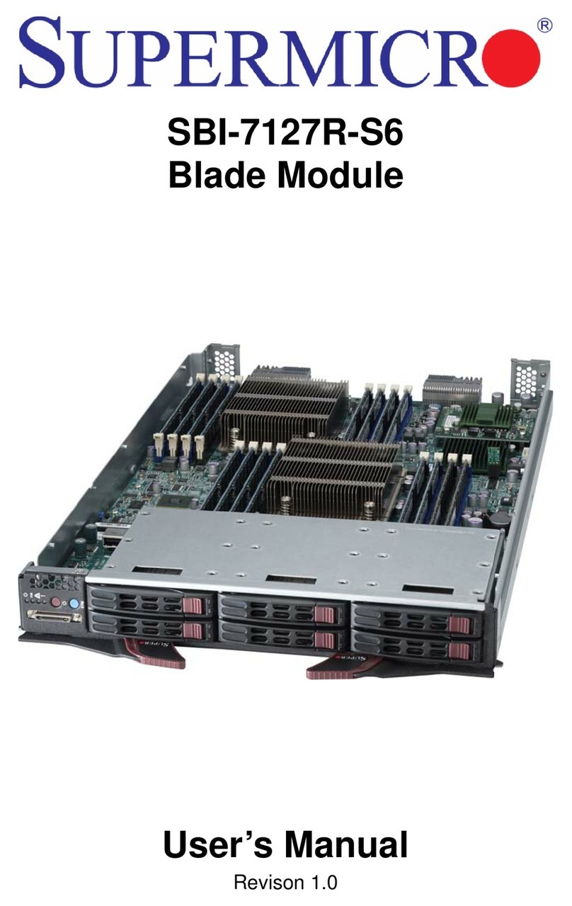
Supermicro SBI-7127R-S6 User manual
Supermicro
Supermicro BPN-SAS2-936EL Series User manual
Supermicro
Supermicro AOC-ATG-b2TG User manual
Supermicro
Supermicro B2SC1-CPU User manual

Supermicro
Supermicro X13SAN-H User manual

Supermicro
Supermicro AOC-A25G-i4SM User manual
Supermicro
Supermicro AOC-SLG4-2H8M2 User manual
Supermicro
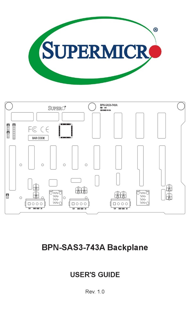
Supermicro BPN-SAS3-743A User manual
Supermicro
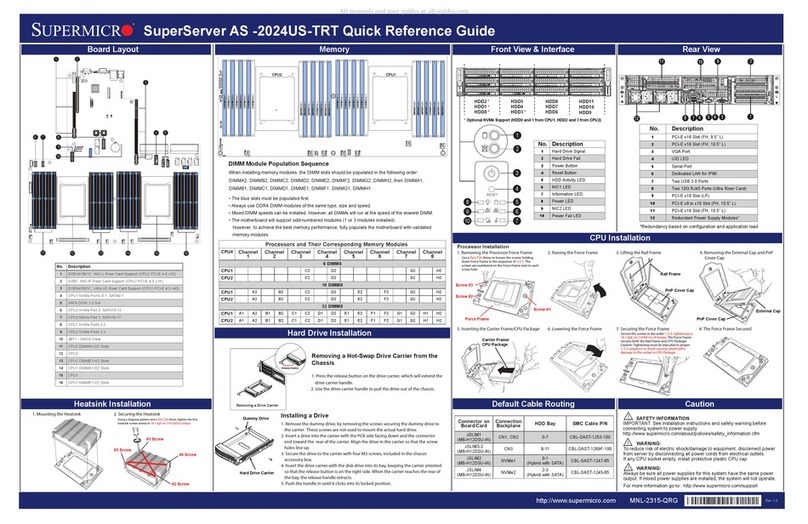
Supermicro SuperServer AS-2024US-TRT User manual
Supermicro
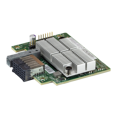
Supermicro AOC-B25G-6CVL User manual
Supermicro
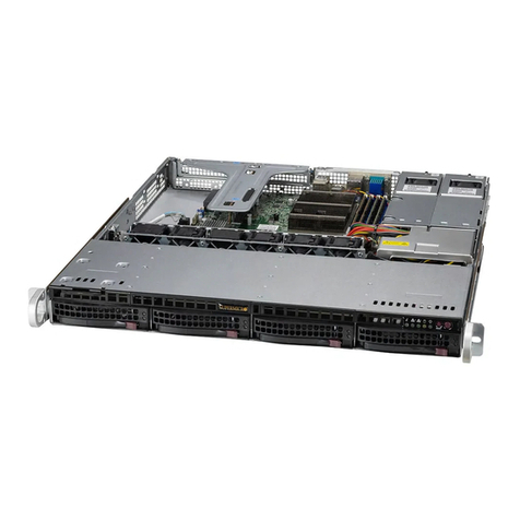
Supermicro SuperServer SYS-510T-M User manual
Supermicro
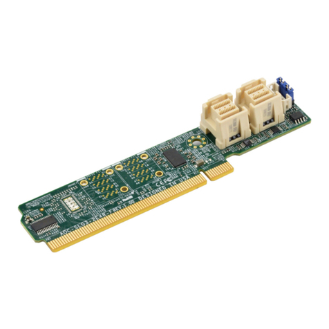
Supermicro AOC-SLG3-2E4R-F User manual
Supermicro
Supermicro BPN-SAS3-833A User manual

Supermicro
Supermicro BPN-SAS3-846EL User manual

Supermicro
Supermicro SBI-7127RG User manual
Supermicro
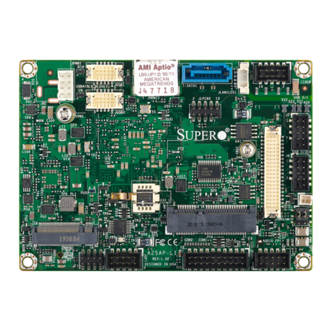
Supermicro A2SAP-L1 User manual
Supermicro
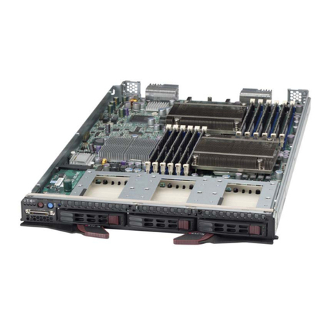
Supermicro SBI-7426T-S3 User manual
Supermicro
Supermicro X11DPFF-SN User manual
Supermicro
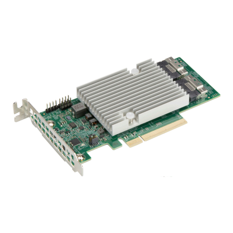
Supermicro AOC-S3816L-L16iT User manual
Popular Computer Hardware manuals by other brands

EMC2
EMC2 VNX Series Hardware Information Guide

Panasonic
Panasonic DV0PM20105 Operation manual

Mitsubishi Electric
Mitsubishi Electric Q81BD-J61BT11 user manual

Gigabyte
Gigabyte B660M DS3H AX DDR4 user manual

Raidon
Raidon iT2300 Quick installation guide

National Instruments
National Instruments PXI-8186 user manual
