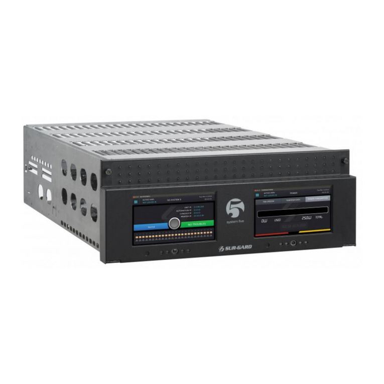
Sur-Gard SG Security MLR-MX User manual

MLR-MX and
Sure Signal CSR
Installation and Operation Manual
Version 1.0
firealarmresources.com

28
FCC Compliance Statement
CAUTION: Changes or modification not expressly approved by Sur-Gard Security Systems Ltd. could void the user's authority to operate the
equipment.
This equipment has been tested and found to comply with the limits for a Class A digital device, pursuant to Part 15 of the FCC Rules. These limits
are designed to provide reasonable protection against harmful interference in a residential installation. This equipment generates, uses, and can radiate
radio frequency energy and, if not installed and used in accordance with the instructions, may cause harmful interference to radio communication.
However, there is no guarantee that interference will not occur in a particular installation. If this equipment does not cause harmful interference to
radio or television reception, which can be determined by turning the equipment off and on, the user is encouraged to try to correct the interference
by one or more of the following measures:
• Re-orient the receiving antenna
• Increase the separation between the equipment and receiver
• Connect the equipment into an outlet on a circuit different from that to which the receiver is connected
• Consult the dealer or an experienced radio/television technician for help
The user may find the following booklet prepared by the FCC useful: "How to Identify and Resolve Radio/Television Interference Problems". This
booklet is available from the U.S. Government Printing office, Washington D.C. 20402, Stock # 004-000-00345-4.
Operation of this equipment in a residential area is likely to cause harmful interference in which case the user will be required to correct the interference
at his own expense.
Industry Canada Compliance Statementt
This Class A digital apparatus meets all requirements of the Canadian interference-causing equipment regulations.
Cet appareil numerique de la Classe A respecte toutes les exigences de reglement sure le materiel brouilleur du Canada.
firealarmresources.com

TABLE OF CONTENTS
Introduction 1
CPM2 ................................................................................... 1
DRL-MX ............................................................................... 1
Supervision........................................................................... 1
Compatibility........................................................................ 1
CPM2 Outputs/Inputs........................................................... 1
MLR-MX Backplane Connection Diagram ............................. 1
System Overview ................................................................. 2
Number of Line Cards Supported.......................................... 2
Approvals............................................................................. 2
Quick Start
Receiver Setup and Operation Without Programming 2
Unpacking ........................................................................... 2
Bench Testing ..................................................................... 2
Power up ............................................................................. 2
Printer Output ...................................................................... 2
Printer Connections............................................................. 2
Computer Connections........................................................ 2
Installation 3
Mounting the Receiver ......................................................... 3
Grounding ............................................................................ 3
Power Supply ....................................................................... 3
Battery Charging Current ...................................................... 3
Radio Connection Diagram ................................................... 4
Initialization .......................................................................... 4
Cold Booting ........................................................................ 4
DRL-MX Controls.................................................................. 5
LCD ...................................................................................... 5
LEDs..................................................................................... 5
Push Buttons......................................................................... 5
Shutdown of Line Card Communication with CPM2.............. 5
CPM2 Error: Display alarm messages ................................... 5
Display Program Version ...................................................... 5
Adjust LCD Contrast ............................................................. 6
Radio Mounting.................................................................... 6
Location of the Antenna ....................................................... 6
Location of Radio Host ......................................................... 6
Changing Networks .............................................................. 6
DRL-MX Displays ................................................................. 6
Additional Troubles for the Mobitex Radio 7
Loss of Radio ........................................................................ 7
Loss of Network ................................................................... 7
Low Signal Strength ............................................................. 7
Unstable Signal..................................................................... 7
Transmission Troubles........................................................... 7
Tx Error 1.............................................................................. 8
Tx Error 2.............................................................................. 8
Radio Status ......................................................................... 8
Radio Status Printer Outputs ................................................. 8
Max Account Limits ............................................................. 8
User Programming ............................................................... 8
Entering Commands ............................................................. 9
Entering Data........................................................................ 9
SG-CPM2 Central Processing Module 10
General Information............................................................ 10
Features.............................................................................. 10
CPM2 Controls ................................................................... 10
CPM2 Operating Mode ...................................................... 11
CPM2 Cold Start-up............................................................ 11
CPM2 in Stand-by Mode .................................................... 11
CPM2 Configuration Mode ................................................. 11
Configuration Options ........................................................ 11
Message Priorities .............................................................. 16
CPM2 Utility Modes 17
[A] Send Computer Messages to Printer ............................. 17
[B] Operator Log-On .......................................................... 17
[C] System Command Mode .............................................. 17
[D] Send Printer Messages to the Printer............................. 17
[E] Examine Printer Messages on Display Screen ................ 18
[F] Examine Computer Messages on Display Screen ........... 18
MLR-MX Computer Interface .............................................. 18
Overview of Communication .............................................. 18
CPM2 COM1 Status Report Messages ................................ 18
COMMUNICATION PROTOCOL WITH CENTRAL STATION
COMPUTER 19
Data Byte Protocol ............................................................ 19
Acknowledgement of the Signal........................................ 19
Basic Signal Protocol ........................................................ 19
SIA Protocol 2 ................................................................... 19
CPM2 EPROM Programming 19
UPS Connection Diagram 20
Appendix A CPM2 Quick Reference Guide 21
CPM2 Utility Modes ........................................................... 21
CPM2 Configuration Mode ................................................. 21
Line Card Command Descriptions....................................... 21
Appendix B Trouble Shooting 22
Appendix C Decimal - Hex - Binary Conversion Chart 23
Appendix D ASCII Character Chart 24
firealarmresources.com

1
INTRODUCTION
The MLR-MX interfaces to the Mobitex network to provide
wireless alarm reception from Sure Signal transmitters.
The MLR-MX’s real-time clock and calendar “stamps” all
information received with the time and date, and all information
may be printed or forwarded to a computer. To ensure security,
adjustment of the clock, calendar and other programming are
protected by password codes.
CPM2
The CPM2 Central Processing Module oversees operation of
the receivers. Along with its built-in keypad and LCD message
screen, the CPM2 features one parallel printer, and two serial
computer interface capability.
DRL-MX
Provides the interface to the Sure Signal CSR (Central Station
Radio) to establish a link on the Mobitex radio. This visual
interface will provide all alarm functionality for the Mobitex
network.
Supervision
The standby battery voltage and connections are supervised.
The Line Cards are also continuously supervised to ensure
uninterrupted communication with the CPM2. Any trouble
conditions are reported on the LCD screens and sent to the
MLR-MX Backplane Connection Diagram
P6
MV3 MV2
P5
P4 P2
R13
R11
R4
R6
R7
R12
printer and the computer.
The DRL-MX Line Card Module verifies communication with
the CPM2. In the event of a malfunction, the operator will be
advised with a visual indicator and the Line Cards will continue
to function. Each line card will continue to receive information,
but will require manual acknowledgement.
The printer is supervised for loss of power, off-line, paper out
and other trouble conditions. The communication link to the
computer through the RS232 port is monitored by the supervisory
“heartbeat” test transmissions.
The DRL-MX supervises the Sure Signal CSR to ensure that the
signal strength and communication are always operational. Should
the unit register low signal strength (>30%) then unit would
display Low Signal Strength.
Compatibility
Central station automation software packages such as:
• M.A.S. • DICE • SIMSII • S.I.S. • GENESIS
Support the MLR-MX Sur-Gard interface.
CPM2 Outputs/Inputs
The CPM2 features four negative-switched outputs (POUT1 is
activated when automation fails), two relay outputs and four
inputs.
CSR
35Ah
175VA
firealarmresources.com

2
System Overview
• Nonvolatile RAM on each DRL-MX card module for
programming and event buffer
• Fast communication between line cards and CPM2
• Flash Download for software upgrades
• 2 Large, easy to read 2-line, 16-characters-per-line, Liquid
Crystal Display screen
• All modules function individually to help ensure uninterrupted
operation during hardware or software upgrades
• Inputs on CPM2 for UPS supervisory
• Maximum 15 lines per receiver
• 256-event memory buffer on each individual line cards
• Real-time clock
• CPM2 features 16-bit micro-controller
• 1 parallel printer port, 2 serial RS232 ports
• Programmable serial port configuration
• Programmable System Functions: computer and printer
• Fast transmission of multiple alarms to the computer and
printer to ensure operator’s quick response
• Continuous verification of the computer-receiver links with
the “heartbeat” function
• Negative-switched outputs on CPM2 (special applications)
• AC-lost detection and standby battery supervision
• Low battery detection and automatic low battery disconnect
to prevent deep-discharge damage to battery
• Operator Acknowledge option
• Mobitex Network Supervision
Number of Line Cards Supported
The system will support a maximum of 15 DRL-MX.
Approvals
Industry Approvals
The MLR-MX is listed for meeting the following approvals:
UL 864 Control Units for Fire-Protective Signaling Systems
UL 1610 Central Station Burglar Alarm Units
This equipment should be installed in accordance with the
requirements of NFPA72, NFPA70 and UL827.
UL Manual Mode
For UL manual mode, each event will activate the internal
buzzer to be acknowledged manually. Each event will also be
sent automatically to the connected printer. For Central Station
applications, the signalling performance of each DACT (DIgital
Alarm Communication Transmitter) shall be manually tracked.
Failure to receive a signal from a DACT over a 24-hour period
shall be handled as a trouble signal.
QUICK START
Receiver Setup and Operation Without
Programming
Unpacking
Carefully unpack the receiver and inspect for shipping damage.
If there is any apparent damage, notify the carrier immediately.
Bench Testing
It is suggested that the receiver be tested before actual installation;
becoming familiar with the connections and setup of the unit
on the work bench will make final installation more straightforward.
The following items are required:
• 16VAC 40 VA transformer
• Sure Signal CSR
• Mobitex Network
• Sure Signal
Power Up
When power is applied, the receiver will beep and will indicate
one or more trouble conditions on the LCD message screen. If
the Line Cards do not have Mobitex network connection, the
DRL-MX modules will beep and their “ALARM” lights will FLASH.
Press the flashing [ACK] button to silence the buzzer. If there
is no computer or printer connected, a trouble message will be
displayed on the CPM2 LCD and the “ACK” light will FLASH.
Press the [ACK] button to silence the CPM2 buzzer.
Printer output
Printer protocol:
LRL-AAAA--NriPMM22
L01-12340Nri|MA00 (x) - no computer output
x = event count
Any parallel 40/80-column printer can be used with the CPM2.
Suggested printers are OKIDATA Microline 182/184 Turbo and
Panasonic KXP11xx, STAR DP8340.
Connect the parallel printer to the MLR2-MX printer output
port using a parallel printer cable.
Printer Connections
The following printers can be used with MLR2-MX:
•Brother M-1309 • Olivetti DDM-100-S
•Citizen 180D • Panasonic KX-P1124
•Epson LQ-570+ • Panasonic KX-P1150
•Okidata ML 182 Turbo • Roland Raven 9101
•Okidata ML 182 Plus • Tandy DMP-206
•Okidata ML 184 Turbo • Star NX-1000
•Star DP8340 Sur-Gard part # SG-DP8340 (The SG-1220P
power supply should be used)
• The SG-1220P (Sur-Gard part number SG-1220P) is a 12V 2A
power supply housed in a metal case with a tamper switch.
It requires one 12VDC sealed rechargeable battery (6 to 25
Ah rating) and one 16VAC 40VA Class 2 wire-in transformer
(Frost FTC4016 or equivalent).
Connect the parallel printer to the MLR-MX printer output port
using a parallel printer cable.
IMPORTANT:
Do not use a printer cable which has only 1
common ground wire.
For UL Listed applications the following UL listed printers can
be used with the MLR2-E:
• Sur-Gard CPU-1150 (Panasonic KX-P1150)
• Sur-Gard CPU DMP-206 (Tandy DMP206)
• DMP SCS-PTR (Okidata Microline 182/184)
Computer Connections
• Connect computer to the MLR-MX RS232 port using a serial
cable to COM1. IMPORTANT: Do not use a null modem cable.
DB25 to DB25 DB25 to DB9
MLR-MX COM1
Computer Automation Connection
firealarmresources.com

3
INSTALLATION
Mounting the Receiver
Install the MLR-MX in a closed 19" rack or cabinet with a
locking rear access door. Cover all unused spaces with blank
metal plates. The LCD screens on the receiver are designed to
be viewed below eye level. If the unit must be mounted where
the screens are above eye level, angle the unit downwards to
improve visibility. The following items can be supplied for a
complete installation:
Stand-up Unit (61.25" tall up to 30 telephone lines)
Part # SG-MLR2-CL
Parts:
• Rack
• Door with lock and ventilation
• Blank plates 21" (2)
• Blank plate 5.25" (3)
• Screws
• Washers
• Clipnuts
• FROST 16V 175VA transformer
• AC Utility Box
• AC Cable Clamps (2)
• 8' Battery Cables
• 18 gauge 3-conductor AC Cable
NOTE: If 30 telephone lines are not used, cover each unused
location with a blank plate
Desk-mount Unit (28" tall up to 30 telephone lines)
Part # SG-MLR2-CM
Parts:
• Rack
• Louvered door back plate
• Blank Plate 1.75"
• Back Plate 7"
• Blank Plates 5.25 (4)
• Screws
• Washers
• Clipnuts
• FROST 16V 175VA Transformer
• AC Utility Box
• AC Cable Clamp for 3/8" cable
• 8' Battery Cable
• 18 gauge 3-conductor AC Cable
NOTES: If 15 modules are not used, cover each unused
location with a blank plate.
Use only UL Listed components with programmable output
on the MLR-MX.
Ex: UL Listed Buzzer part # PKB5-3A0
UL Listed Relay part # HAS-112-12
Grounding
For maximum resistance to static and electrical noise, the 19"
rack frame should be connected to earth ground through the
AC utility box.
Power Supply
Ensure that all electrical connections are made correctly. After
verifying all connections, connect the RED and BLACK leads to
a 12VDC sealed rechargeable battery. Be sure to observe polarity
when connecting the battery. When the battery is connected,
test the system under battery power only.
If a separate DC input is used to power the LCD backlighting
during AC power failures, connect it to the BLGT terminal. It
must be a listed Fire-Protective Signalling System power supply
rated 12VDC. Connect the positive lead from the DC supply to
the BLGT terminal; connect the negative lead from the DC
supply to the GND terminal.
CAUTION: Connecting a positive (+) terminal to a nega-
tive (-) terminal may cause a fire and possibly serious personal
harm.
For 4-hour standby, a 12-volt 35Ah rechargeable battery should
be used in conjunction with an engine driven power Generator.
Battery Charging Current
The maximum battery charging current is factory set at 1A.
firealarmresources.com

4
Radio Connection
SURE SIGNAL CSR
P
6
P
5
P4 P2
R13
R11
R4
R6
R7
R12
To cancel the Cold Boot and change the Line Card number,
press the [CANCEL] button. To perform the Cold boot, press
the [ACK] button. When the [ACK] button is pressed, this message
will be displayed for 1 second:
CHANGE LN NBRCHANGE LN NBR
CHANGE LN NBRCHANGE LN NBR
CHANGE LN NBR
ACK:yes SEL:noACK:yes SEL:no
ACK:yes SEL:noACK:yes SEL:no
ACK:yes SEL:no
After 1 second, or if the [CANCEL] button was pressed to
cancel the Cold Boot, this message will be displayed:
LINE CARD #:00LINE CARD #:00
LINE CARD #:00LINE CARD #:00
LINE CARD #:00
ACK:up SEL:downACK:up SEL:down
ACK:up SEL:downACK:up SEL:down
ACK:up SEL:down
Press the [ACK] or [CANCEL] buttons to scroll through the list
of valid numbers for the line card. The list will scroll through
the hexadecimal numbers “01” to “0F” (1 to 15); when the
desired number is displayed, press the [ACK] and [CANCEL]
buttons together.
The serial connection is a straight through 9 pin male to 9 pin
female connection.
Initialization
It is recommended that a DRL-MX Cold Start-up be performed
when the unit is updated with a new program version.
After the cold start-up, check the configuration information listed
in the Quick Reference Guide to make any required changes for
your particular application.
Cold Booting
On powered up press both the ACK button and the Select
button. The following will be displayed:
SYST COLD BOOTSYST COLD BOOT
SYST COLD BOOTSYST COLD BOOT
SYST COLD BOOT
ACK:yes SEL:noACK:yes SEL:no
ACK:yes SEL:noACK:yes SEL:no
ACK:yes SEL:no
NOTE: For UL installation the
Sure Signal CSR has been
approved with Altronix
AL400UL power supply.
To 12V DC +
-
firealarmresources.com

5
Shutdown of Line Card Communication with CPM2
A Line Card may be temporarily removed from CPM2 polling for
testing and maintenance purposes; refer to “CPM2 Utility Modes”
for information on shutting down a line card. While in the shutdown
mode, the Line Card will retain up to 255 alarm messages in its
event buffer. When the Line Card is shut down, the “Trouble” light
will come ON and this message will be displayed:
DRL-MX – Line #0DDRL-MX – Line #0D
DRL-MX – Line #0DDRL-MX – Line #0D
DRL-MX – Line #0D
<<-LC SHUTDOWN>><<-LC SHUTDOWN>>
<<-LC SHUTDOWN>><<-LC SHUTDOWN>>
<<-LC SHUTDOWN>>
CPM2 Error; Display Alarm Messages
If the DRL-MX cannot detect CPM2 polling and there are no
alarm events in the event buffer, this message will be displayed:
DRL-MX – Line #0DDRL-MX – Line #0D
DRL-MX – Line #0DDRL-MX – Line #0D
DRL-MX – Line #0D
<<-CPM ERROR->><<-CPM ERROR->>
<<-CPM ERROR->><<-CPM ERROR->>
<<-CPM ERROR->>
If alarm messages cannot be sent to the CPM2 because of the
error, the DRL-MX will display the oldest message which has
not been manually acknowledged. The “Alarm” light will FLASH
and the sounder will beep if the “Mute Buzzer” Option is
programmed as [00] or [01].
When a CPM2 Error is present, each alarm must be manually
acknowledged. Press the [ACK/FUNCTION] button to acknowledge
the alarm and silence the Line Card sounder. If several alarms
have been received but cannot be sent to the CPM2, they will
have to be individually acknowledged; when all alarms are
acknowledged, the Line Card sounder will be silenced.
Up to 128 alarm messages for the printer and computer will be
retained in the CPM2 event buffer. When the event buffer is full,
the oldest messages will be deleted as new events are recorded.
When the CPM2 Error condition is corrected, the alarm messages
in the event buffer will be transmitted to the CPM2.
Display Program Version
PROGRAM VERSIONPROGRAM VERSION
PROGRAM VERSIONPROGRAM VERSION
PROGRAM VERSION
ACK:menu SEL:selACK:menu SEL:sel
ACK:menu SEL:selACK:menu SEL:sel
ACK:menu SEL:sel
With this message displayed, press the [SELECT] button; the
date and the software version number will be displayed as
shown below:
SG - DRLMXSG - DRLMX
SG - DRLMXSG - DRLMX
SG - DRLMX
Jan 19,99 V 1.10Jan 19,99 V 1.10
Jan 19,99 V 1.10Jan 19,99 V 1.10
Jan 19,99 V 1.10
Press [ACK] and [SELECT] together to return to the Stand-By Mode.
DRL-MX Controls
LCD
Displays incoming data, programming and other information.
The display is backlit for visibility in low light environments.
LEDs
•Trouble: Lights up on Linecard Shutdown, CPM Error Restores
when Line Card Reactivated, CPM Restored.
•RX: Signal received from the radio.
•TX: Signal sent to the radio.
•Radio Detect: Lights up when Network is Absent. Restores
when Network is Present.
•TX ACK: Acknowledge of an alarm LED.
•Low Signal: Signifies that the RSSI value is below 30% and
can only be restored if it reaches 45%.
•ACK: Lit when an Acknowledged is required in manual mode.
•Watchdog: Blinks to indicate that the software is operating
•TX Error: It indicates Transmission Error. Restores when
Transmission Successful is received.
•Power: Power will be on when the Line card has power.
Push-buttons
•Select: It is used in (menu) scrolling down in standby mode
Used in selecting menus.
•Ack.: Acknowledging alarms in manual mode. Scroll up in
standby.
Momentarily depressing and releasing a button will register as
a single input or keystroke. Pressing and holding a button for
approximately 1 second will register as a repeating input or
keystroke. For example, to quickly scroll through a list of items,
press and hold the appropriate button, rather than pressing the
button repeatedly.
firealarmresources.com

6
Adjust LCD Contrast
Adjust CONTRASTAdjust CONTRAST
Adjust CONTRASTAdjust CONTRAST
Adjust CONTRAST
ACK:menu SEL:selACK:menu SEL:sel
ACK:menu SEL:selACK:menu SEL:sel
ACK:menu SEL:sel
With this message displayed, press the [SELECT] button to adjust the LCD
screen’s contrast. When the [SELECT] button is pressed, this message will
be displayed:
Adjust CONTRASTAdjust CONTRAST
Adjust CONTRASTAdjust CONTRAST
Adjust CONTRAST
••••••••
••••••••
••••
Press the [ACK] button to increase the contrast; press the [SELECT] button
to reduce the contrast. The display will indicate the contrast level on the
second line.
Press [ACK] and [SELECT] together to return to the Stand-By Mode.
This section will outline the procedure for enrolling the Mobitex
radio onto the network. This section will also outline additional
features and functions that are to be added to the MLR-MX in
order for the receiver to operate correctly.
Sure Signal CSR Mounting
The following are guides for help placing a radio unit.
Location of the Antenna
The antenna should be placed in a location that will give a
signal strength of 80 to 100%. This will have to be flushed out
more completely when an antenna kit has been put together.
Location of the Sure Signal CSR Host
The radio host should be mounted on a wall that is away from
directly behind the receivers. As well, the radio host needs to
be within the required distance of the DRL-MX in order to
connect the RS232 cable between the receiver and the radio
host. This mounting location will also require ready access to
the drop through location of the antenna cable. Maximum distance
is 100 feet.
Changing Networks
There may be another network which you wish to use for a
radio that is currently operating, or for other radios that are to
be installed. In order to change the current provider for the
radio that requested the Network List. Once the provider has
set up the service the following steps will have to be followed
in order to change networks. Using the programming mode at
the CPM2, request a Network List. The following steps need to
be followed in order to check the network that is currently
being used, a list of the networks available and the attempt to
change networks.
At the CPM2, enter into programming mode.
Select the line (radio) that needs to be changed from the current
network to a new network.
Network options
•2C: current network request
In the code section, a nonuser number needs to be entered.
The MLR-2E will send a request network name to the radio.
The radio will respond with the current network name.
The printer will then print:
L11- Cantel
L11 is the receiver and line number; Cantel is the current
network.
Note: This network name does not need to be saved in the
MLR-MX.
•2D: request network list - print list to printer
In the code section, a nonzero number needs to be entered.
The MLR-MX will send a request network list to the radio.
The radio will respond with the reply network list.
The printer will then print:
L11- (01) Cantel
L11- (02) Bell
L11- (03) BCBell
L11- (04) SackBell
•2E: change network – enter number of the requested network,
or 00 in order to exit the section without changing the network.
When a nonzero number is entered, the MLR-MX will send
a change to other network to the radio.
The radio will respond with the current network name.
If 00 is entered, the receiver will request the network name
Once the programming mode has been exited, or a network
has been selected, then the network list can be removed
from RAM.
DRL-MX Displays
The two displays that are on the DRL-MX display boards will
be fully utilized. The top display indicates the status of the
Mobitex radio host that is connected to the receiver. The bottom
display will only be used to indicate received signals from Sure
Signal that are using the Mobitex radio network.
Top Display
The top display is used for displaying the host radio MAN, the
radio signal strength, as well as any trouble conditions that
occur during operation. The radio signal strength is taken out
of the radio status.
The following is an example of how the top display will appear,
under normal operation.
5004455 [45%]5004455 [45%]
5004455 [45%]5004455 [45%]
5004455 [45%]
Network PresentNetwork Present
Network PresentNetwork Present
Network Present
In the example, the radio signal strength is 45%, and the
network was detected when the radio last communicated a
radio status to the receiver.
Bottom Display
The bottom display gives the information of the inbound
transmissions from the Sure Signals. The Sure Signal will be
the account number in decimal, for format type 1, that will be
displayed, and then the SIA event after. Inbound format type
2 will have an account number in the MPAK payload. Also,
the line card that the DRL-MX is assigned as will be displayed.
The following is an example of how a received transmission
will be displayed on the bottom display.
L11-5004454 Nri1L11-5004454 Nri1
L11-5004454 Nri1L11-5004454 Nri1
L11-5004454 Nri1
MA00MA00
MA00MA00
MA00
In this example, this DRL-MX is receiver 1, line 1 to the CPM2.
The Sure Signal MAN, and account number, is 5004454, and
the event occurred on partition 1, and the event was a [A] key
alarm.
This display will follow the regular options of a line card display
on a regular MLR-MX.
firealarmresources.com

7
ADDITIONAL TROUBLES FOR THE SURE
SIGNAL CSR
All of the trouble conditions that occur, will be displayed on
the top display, sent to the printer, and sent to the automation
package. The information at the printer and the LCD will be
plain English messages. The output to the automation package
will be SIA, using the account code ‘0000’.
Loss of Radio
The MLR-MX requests a radio status every 5 seconds from the
Sure Signal CSR. If the receiver does not get a radio status back
within 250 msec., the radio will be considered as not connected.
Also, if there is not a radio status 30 seconds after a transmission
is attempted, then the loss of radio trouble will be indicated.
The display will show the following.
Radio Not FoundRadio Not Found
Radio Not FoundRadio Not Found
Radio Not Found
The printer will output the following error:
L11- Loss of Radio
The receiver will output the following line error message to the
automation package.
S011[0000|Nri1YD00]
When the Sure Signal CSR is restored, the LCD will display the
serial number, signal strength, and radio status.
The printer will print:
L11- Radio Restored
The receiver will output the following line restoral message to
the automation package.
S011[0000|Nri1YE00]
Loss of Network
The status of the Network is checked every 5 seconds. If the
radio can not find the network, there will be a trouble indicated.
The radio must have lost the network one time before a trouble
is generated.
The radio status indicates to the receiver whether the Mobitex
network is present or not. The display will show the following
message.
Network AbsentNetwork Absent
Network AbsentNetwork Absent
Network Absent
The printer will output the following error:
L11- Network Absent
The receiver will output the following line error message to the
automation package.
S011[0000|Nri1NT00]
When the network is restored, the LCD will display the serial
number, signal strength, and radio status.
The printer will print:
L11- Network Present
The receiver will output the following line restoral message to
the automation package.
S011[0000|Nri1NR00]
Low Signal Strength
The radio status will indicate to the receiver the signal strength
between the Sure Signal and the network. The display will
show the following message.
5004455 [22%]5004455 [22%]
5004455 [22%]5004455 [22%]
5004455 [22%]
Low SignalLow Signal
Low SignalLow Signal
Low Signal
The printer will output the following error:
L11- Low Sig. [22%]
The receiver will output the following line error message to the
automation package.
S011[0000|Nri1XL00]
When the network is restored, the LCD will display the serial
number, signal strength, and radio status.
The printer will print:
L11- Sig. Rstr. [45%]
The receiver will output the following line restoral message to
the automation package.
S011[0000|Nri1YE00].
Low signal will occur at 30% and will restore at 45%
Unstable Signal
This status is sent whenever 2 consecutive low signals are
received within an hour to indicate that the radio location is
not recommended.
Transmission Troubles
There are a number of transmission errors that are possible and
will be outlined in this section.
There are 2 locations that the transmission troubles come from;
the transmit MPAK status in the radio status in the frame data,
and the MPAK flags. The troubles will be divided into both categories.
Before a transmission trouble is indicated, there is an attempt
to correct the trouble, with a maximum of 5 retries. If the
transmissions do not get through to the destination, the last
trouble will display the reason for the failed transmission. The
display will show the following message.
5004455 [45%]5004455 [45%]
5004455 [45%]5004455 [45%]
5004455 [45%]
TX. ErrorTX. Error
TX. ErrorTX. Error
TX. Error
The printer will output the following error for troubles indicated
by the MPAK flags: L11- TX. Error 1 (
error type from table
).
The printer will output the following error for troubles indicated
by the radio status: L11- TX. Error 2 (
error type from table
).
The receiver will output one of the following line error messages
to the automation package.
S011[0000|Nri1UAxx] for type 1 transmission errors
S011[0000|Nri1UTxx] for type 2 transmission errors.
xx – error type from the tables below.
When the radio successfully transmits, the trouble will be
considered to be cleared. The LCD will display
TX SuccessfulTX Successful
TX SuccessfulTX Successful
TX Successful
The printer will print: L11- TX. Successful
The receiver will output the following line restoral message to
the automation package.
S011[0000|Nri1UJ00]
firealarmresources.com

8
TX Error 1 (from MPAK flags)
TypeError
02 In Mail
03 No Transfer
04 Illegal
05 Congest
06 Error
07 Busy
TX Error 2 (from Radio Status)
TypeError
80 Previous “Transmit MPAK” not complete.
81 LOGON specified an already logged-in PMAN.
82 PMAN not logged in. Can’t use it as Source MAN.
83 FlexList Full for LOGON MPAK request.
84 Bad MPAK Type.
Type Error
85 Bad MPAK Traffic state.
86 Bad MPAK transmit flags.
87 Bad Address List.
88 Bad destination MAN.
89 Incorrect length.
90 No radio coverage.
91 Transmitter is off.
92 Radio is in DIE state.
Alarm Acknowledgment
Alarms are received and decoded to SIA protocol and should
also be Acknowledged using SIA DATA ACK.
The SIA DATA ACK is 38h which will be sent with the MPAK
packet. This will include the Time bytes and the Source/Destination
MAN numbers and an ACK counter.
Radio Status
Radio Status Printer Outputs
The following messages will describe the printer outputs depending if the bit was set high or low.
Bit Description Set High Set Low
7 Network Contact L11-0000—Network Present L11-0000—Network Absent
6 Transmission Allowed L11-0000—Rad Trans: LIVE L11-0000—Rad Trans: DIE
5 Transmitter is On L11-0000—Transmitter ON L11-0000—Transmitter OFF
4 Power Save Enabled Currently not used Currently not used
3 Receiver Ready L11-0000—Rad Rec: Ready L11-0000—Rad Rec: not Rdy
2 Low Battery Currently not used Currently not used
1 Radio Shutdown L11-0000—Radio Shutdown L11-0000—Radio Restored
0 Battery Charging Currently not used Currently not used
Maximum Account Limits
When the monitoring station is giving the installer a radio
MAN for the Sure Signal to report to, there should be no more
that 1000 accounts reporting to a single receiver line that has
a Mobitex radio host.
User programming
Option 01: linecard number
Option 0F: mute buzzer
Option 02: linecard number length
Option 2C: network name to printer
Option 2D: network list to printer
Option 2E: change to other network
Option 72: com. select
Option 73: printer select
Option 74: equivalent line
Option 75: receiver number
Note: all other options will be set as reserved.
Option 01: Linecard Number, this sets the Physical number on the
linecard and all reports are reported using this linecard number.
Option 0F: Mute Buzzer option. This option is for enabling and
disabling the buzzer.
Option 02: Linecard Number Length, which sets the length of
the physical number on the linecard.
Option 2C: Current Network Request, when this option is enabled
to 01, the DRL-MX will send a request network name to the
radio. The network will respond with the current network name
and the printer will print:
L11-Cantel
L11 - Receiver and linecard number
Cantel - Current Network Name
Option 2D: Request Network list, when this option is enabled
to 01, the DRL-MX will send a network list to the radio. The
radio will respond with the reply network list and the printer
will then print:
L11- 01 Cantel
L11- 02 Bell
L11- 03 BCBell
L11- 04 SackBell
If option 2E is entered, then the network names should be
saved in RAM until programming is exited.
Option 2E: Change Network, in this option enter the number
of the requested network, or 00 in order to exit the section
without changing the network. When a nonzero is entered, the
DRL-MX will send another change to the network via radio.
The radio will respond to the current network name:
Accepted – new network name will come up to the printer
Declined – old network name will come up to the printer
If 00 is entered – the receiver will request the network name.
Once the programming mode has been exited, or a network has
been selected, then the network list can be removed from RAM.
Note: The current network name is not stored in the receiver.
Option 72: Computer Select option. This option is used for
enabling and disabling computer output.
Option 73: Printer Select option. This option is used for enabling
40/80 column printer or disabling printer output.
Option set to: 00 Disabled
01 40 column printer Enabled
03 80 column printer Enabled
Option 74: Equivalent Line. This option is used for reporting
a different line number on the printer and computer, but the
linecard still keeps the characteristics of its physical number.
Option 75: Receiver Number, this sets the Physical number on the
receiver and all reports are reported using this receiver number.
firealarmresources.com

9
When “01” is keyed in, the value will appear on the display
as shown below:
LCard:01 Comd:F7LCard:01 Comd:F7
LCard:01 Comd:F7LCard:01 Comd:F7
LCard:01 Comd:F7
Op:36 Cd:01 Sc:__Op:36 Cd:01 Sc:__
Op:36 Cd:01 Sc:__Op:36 Cd:01 Sc:__
Op:36 Cd:01 Sc:__
Note that “Sc” is not used and stays blank. After the value is
entered at “Cd:”, press [ACK] or [Escape] to save the changes.
NOTE: If the [Escape] button is pressed before the value
at “Cd:” is entered, the changes will not be saved.
Verifying Data
• To verify the changes just entered, press and hold the [ACK]
button on the DRL-MX until this message is displayed:
Display OptionsDisplay Options
Display OptionsDisplay Options
Display Options
ACK:menu SEL:selACK:menu SEL:sel
ACK:menu SEL:selACK:menu SEL:sel
ACK:menu SEL:sel
• Press the [SELECT] button to view the system configuration;
this message will be displayed:
L01 #00L01 #00
L01 #00L01 #00
L01 #00 0000
0000
00
LCard Numb: 05LCard Numb: 05
LCard Numb: 05LCard Numb: 05
LCard Numb: 05
Press the [ACK] button to scroll forward through the configuration
displays until you reach option 36, or press the [SELECT] button
to scroll backwards through the configuration displays. Press
[ACK] and [SELECT] together to return to the Stand-By Mode.
Entering Commands
Commands are entered on the CPM2 keypad using the following
format: LCard; Comd; Op; Cd; Sc
•LCard: “Line Card” is the Line Card number; enter a
hexadecimal number from 01 to 0E for Line Cards 1 through
14.
•Comd: “Command” is the Command; enter a command from
the list above
•Op: “Option” indicates a function that is part of a command;
the following sections of this manual will explain which
commands have options. Enter a 2-digit hexadecimal number
•Cd: “Code” is the code or value to be programmed for the
Option; enter a 2-digit hexadecimal number
•Sc: “Second Code” is a code or value that is only used with
SCADA commands; if required, enter a 2-digit hex number
Entering Data
The following is how to enter the Programming Password and
program an option in the F7 Options Programming section:
• Press and hold the [C] button on the CPM2 until the CPM2
displays the following message:
Enter PASS-WORDEnter PASS-WORD
Enter PASS-WORDEnter PASS-WORD
Enter PASS-WORD
****
The default password is “CAFE”. Enter the password using
the CPM2 keypad.
• When the password is entered, the CPM2 will display this
message:
LCard:__ Comd:__LCard:__ Comd:__
LCard:__ Comd:__LCard:__ Comd:__
LCard:__ Comd:__
Op:__ Cd:__ Sc:__Op:__ Cd:__ Sc:__
Op:__ Cd:__ Sc:__Op:__ Cd:__ Sc:__
Op:__ Cd:__ Sc:__
• Enter the Line Card number. In this example, Line Card 01
will be used. When “01” is keyed in, the number will appear
on the display as shown below:
LCard:01 Comd:__LCard:01 Comd:__
LCard:01 Comd:__LCard:01 Comd:__
LCard:01 Comd:__
Op:__ Cd:__ Sc:__Op:__ Cd:__ Sc:__
Op:__ Cd:__ Sc:__Op:__ Cd:__ Sc:__
Op:__ Cd:__ Sc:__
• Enter the Command number. In this example, the F7 Options
Programming command will be used. When “F7” is keyed
in, the command will appear on the display as shown below:
LCard:01 Comd:F7LCard:01 Comd:F7
LCard:01 Comd:F7LCard:01 Comd:F7
LCard:01 Comd:F7
Op:__ Cd:__ Sc:__Op:__ Cd:__ Sc:__
Op:__ Cd:__ Sc:__Op:__ Cd:__ Sc:__
Op:__ Cd:__ Sc:__
• Enter the Option number. In this example, Option [36] will
be changed. When “36” is keyed in, the Option will appear
on the display as shown below:
LCard:01 Comd:F7LCard:01 Comd:F7
LCard:01 Comd:F7LCard:01 Comd:F7
LCard:01 Comd:F7
Op:36 Cd:__ Sc:__Op:36 Cd:__ Sc:__
Op:36 Cd:__ Sc:__Op:36 Cd:__ Sc:__
Op:36 Cd:__ Sc:__
• Enter the value to be programmed at Option 36. In this example,
01 will be programmed at Option [36] to enable it.
firealarmresources.com

10
SG-CPM2 CENTRAL PROCESSING
MODULE
The CPM2 is the central processing module that monitors the
DRL-MX Line Cards and forwards the information from the Line
Cards to the computer and printer. The CPM2 is capable of
monitoring a maximum of 14 telephone lines from 7 DRL-MX
modules.
General Information
The CPM2 16-bit micro-controller and real-time assembly language
program running at 16 MHz allows the system to quickly and
efficiently execute several tasks at the same time. The use of
a unique menu display system enhances the ease of use for the
operator and makes the system configuration and programming
simple and efficient. Several diagnostic modes are available to
assist the operator in troubleshooting and maintenance.
Features
• Multi-tasking allows the receiver to perform functions that
might otherwise be delayed by a slow computer
acknowledgment response
• Fast internal communication results in practically no delay in
transfer of information between the Line Card and the CPM2.
The CPM2 is capable of polling 14 Line Cards in 1 second
• 128-event printer alarm message buffer
• 128-event computer alarm message buffer
• LCD contrast easily adjusted
Liquid Crystal Display: 2-line, 16 character per line liquid crystal
display; backlit for easy reading in low level light
“Option” light: Indicates the state of the “Option” programmable
output. Flashing 2 seconds ON, 2 seconds OFF, with the
standard program.
[ACK] button: Used to manually acknowledge an alarm event
when a computer is not connected to the receiver or when
the UL Receiver Option is enabled. Press the [ACK] button
to turn the “ACK” light OFF and silence the buzzer. The
[ACK] button is also used in the Configuration Mode to
select menu items.
“ACK” light: Flashes when a message is received from the Line
Card and COM1 is disabled or disconnected
[Enter] button: Executes a command or scrolls the display to the
next message.
“TX” light: Monitors the COM1 transmission signal
[Backspace] button: Used to erase errors or move the cursor
back one character; also used to scroll the display back to
the previous message.
“RX” light: Monitors the signal received from the computer
connected to COM1.
[Escape] button: Used to save changes and exit a mode; also
used for other functions when indicated on the display screen.
“TROUBLE” light: Illuminates when a trouble condition is present
(not used).
“AC” light: Indicates that AC power is present.
• Ability to individually examine each Line Card message
• “Cold boot” option allows easy installation of default
configuration
• Built-in diagnostic “debug” mode allows each Line Card to
be monitored individually
• Serial Port COM1 features LED indicators for Transmit (Tx)
and Receive (Rx) functions
• Available COM1 baud rates: 110, 150, 300, 600, 1200, 2400,
4800, 9600, 19200 or 38400
• COM1 Data bits: 7, 8 or 9
• COM1 Parity: Even, odd or none
• COM 1 Stop Bits: fixed at 1
• Built-in Serial Communication Diagnostic Mode for COM1.
The technician can test the communication with the central
station computer and monitor what is being transmitted to
and received from the computer
• Two programmable outputs, one with front panel LED indicator
• Buzzer mute option for system testing
• System menu for easy programming and diagnostics
• Software Version 2.1 supports SCADA Line Cards for networks
of receivers
• Software Version 2.1 supports line cards and CPM2
programming through computer
CPM2 Controls
firealarmresources.com

11
CPM2 Operating Mode
Computer Reply
The CPM2 will consider any character other than “06H” or
“15H” as the computer being absent.
CPM2 Cold Start-up
The “cold boot” should be performed to install the default
system software.
Follow the procedure described here to perform a “cold boot”
of the CPM2.
• Remove the CPM2 from the card cage
• Turn the “PROG EN” (Program Enable) switch ON. The Program
Enable switch is located on the left side of the CPM2 unit;
use a small screwdriver to turn the switch ON by turning it
clockwise.
• Reinstall the CPM2 in the card cage, but do not fasten the
mounting screws. The CPM2 should power up and this message
will be displayed:
SYST COLD BOOT?SYST COLD BOOT?
SYST COLD BOOT?SYST COLD BOOT?
SYST COLD BOOT?
Ent=Yes Bsp=NoEnt=Yes Bsp=No
Ent=Yes Bsp=NoEnt=Yes Bsp=No
Ent=Yes Bsp=No
• Press the [Enter] button to perform the “cold boot”. This
message will be displayed:
SYST COLD BOOTSYST COLD BOOT
SYST COLD BOOTSYST COLD BOOT
SYST COLD BOOT
Executing!Executing!
Executing!Executing!
Executing!
After approximately 1 second, this message will be displayed:
Please Turn OffPlease Turn Off
Please Turn OffPlease Turn Off
Please Turn Off
Program Switch!Program Switch!
Program Switch!Program Switch!
Program Switch!
The CPM2 will remain in an inoperative mode until the Program
Enable switch is turned OFF.
• Pull the CPM2 out of the card cage
• Use a small screwdriver to turn the Program Enable switch
OFF by turning it counterclockwise.
• Reinstall the CPM2 in the card cage and secure the faceplate
screws
The CPM2 is now ready for operation. Set the clock and calendar
and configure the CPM2.
CPM2 in Stand-By Mode
When the CPM2 is in Stand-By mode, a message similar to this
will be displayed:
*FEB-23 07:30:45*FEB-23 07:30:45
*FEB-23 07:30:45*FEB-23 07:30:45
*FEB-23 07:30:45
Scanning 0E (14)Scanning 0E (14)
Scanning 0E (14)Scanning 0E (14)
Scanning 0E (14)
This indicates that the system is ready to receive data from the
Line Cards and input from the numeric keypad and push buttons.
CPM2 Configuration Mode
The Configuration Mode allows programming of the various features
and options available on the CPM2. To enter the Configuration
Mode, press the [Escape] button; this message will be displayed:
Enter MASTER-IDEnter MASTER-ID
Enter MASTER-IDEnter MASTER-ID
Enter MASTER-ID
********
********
****
Enter the Master Access Code using the keypad; the default Master
Access Code is “CAFE”. When the access code is entered, the
screen will display the first option in the Options Menu:
01:Sys Date/Time01:Sys Date/Time
01:Sys Date/Time01:Sys Date/Time
01:Sys Date/Time
Ent:+ Bs:- Ack:SEnt:+ Bs:- Ack:S
Ent:+ Bs:- Ack:SEnt:+ Bs:- Ack:S
Ent:+ Bs:- Ack:S
Press the [Enter] button to display the next menu item, or press
the [Backspace] button to display the previous menu item;
press the [ACK] button to select the menu item presently displayed
on the screen.
Configuration Options
The CPM2 features 28 configuration options:
01 System Date and Time
02 System Passwords
03 Number of Line Cards
04 Printer Select
05 COM1 Configuration
06 COM1 Format
07 Acknowledge Wait Delay
08 Heartbeat Select
09 COM2 Configuration
10 COM2 Format
11 Contrast Adjust
12 UL Receiver Option
13 Erase Memory
14 Mute Buzzer
15 Keep Last Message
16 Debug ComPort
17 Test 9v/12v Batt
18 Debug Line Card
19 Program Version
20 Monitor Battery
21 Year / Second
22 Force Reset
23 Change Receiver Number
24 COM1/2 Control
25 Printer Control
26 Printer Test
27 Printer Width
28 Tamper Input
Option 01: Setting the Clock
Option [01] allows the CPM2 date and time to be set. Press the
[ACK] button when the “01: Sys Date/Time” message is displayed;
this message will be displayed:
(D/M/Y) 23/02/93(D/M/Y) 23/02/93
(D/M/Y) 23/02/93(D/M/Y) 23/02/93
(D/M/Y) 23/02/93
(H:M:S) 07:30:45(H:M:S) 07:30:45
(H:M:S) 07:30:45(H:M:S) 07:30:45
(H:M:S) 07:30:45
Enter the date and time using the numbers 0 through 9 only.
Press the [Enter] button to move the cursor one character to the
right; press the [Backspace] button to move the cursor one space
to the left.
When the date and time are entered, press the [Escape] button;
when the [Escape] button is pressed, the next Configuration
Option will be displayed on the screen.
Note that if “0” or a number greater than “12” is programmed for
the month, the screen will display the word “Nul” in place of the
month while in the Stand-By mode. “Nul” will also be displayed
for the time if the time has not be programmed properly.
firealarmresources.com

12
Option 02: Changing System Passwords
Option [02] allows the CPM2 passwords to be changed or
erased. Press the [ACK] button when the “02: Sys Passwords”
message is displayed; this message will be displayed:
PassID#0: xxxx
Operator: S.G.
Sixteen 4-digit passwords are available for use on the CPM2.
Password 0 is the Master Password, and Passwords 1 through
F may be assigned to individual operators. Two letters,
representing the initials of the operator, may be assigned to
each Password to help in identifying the operator.
When this option is entered, a cursor will appear beneath the
first character in the 4-digit Password. Enter a new Password
using the 0 through 9 and the A through F keys.
To enter the operator’s initials, use the [0] and [1] keys to scroll
forward or backward through the alphabet. When the desired
letter is displayed, press the [Enter] button; the cursor will
move to the next character. To move the cursor to the previous
character, press the [Backspace] button.
When the Password and initials have been entered, press the
[Escape] button; the next Password will be displayed. When all
Passwords have been programmed, the display will advance to
the next Configuration Option.
Option 03: Change the Number of Line Cards
Option [03] is used to set the number of Line Cards polled by
the CPM2. Press the [ACK] button when the “03: Numb of
Lcard” message is displayed; this message will be displayed:
#LnCard Attached#LnCard Attached
#LnCard Attached#LnCard Attached
#LnCard Attached
E Change to: xE Change to: x
E Change to: xE Change to: x
E Change to: x
Enter a number from 1 to E to indicate how many Line Cards,
from 1 to 14, are to be polled by the CPM2. When the new
number is entered, press the [Enter], [Backspace], or [Escape]
button; the screen will then display the next Configuration Option.
Option 04: Select Printer Function
Option [04] determines how the printer connected to the CPM2
will operate. Press the [ACK] button when the “04: PrinterSelect”
message is displayed; this message will be displayed:
Prter Config As:Prter Config As:
Prter Config As:Prter Config As:
Prter Config As:
Bkup:0 Enable:1Bkup:0 Enable:1
Bkup:0 Enable:1Bkup:0 Enable:1
Bkup:0 Enable:1
Enter a digit from 0 through 1 for both “Bkup” and “Enable”
according to the chart below:
Bkup Enable Printer Operation
0 0 Bypass printer
0 1 Enable printer (default setting)
1 0 Enable printer only if COM1 is in failure
1 1 Enable printer only if COM1 is in failure
(same as above)
If “Bkup” is programmed as “1”, messages will only be sent to
the printer if an acknowledge signal is not received from COM1.
When using the Star DP8340 printer, the CPM2 is able to print
in both red and black. If an IBM compatible printer is selected,
the CPM2 will print in black only.
When programming is complete, press the [Escape] button;
when the [Escape] button is pressed, the next Configuration
Option will be displayed on the screen.
Option 05: COM1 Configuration
Option [05] determines the baud rate, data bits and parity to be
used on COM1. Press the [ACK] button when the “05: Com#1
Config.” message is displayed; this message will be displayed:
Com#1 Config As:
Br:12 Da:7 Pa:2
Br: Baud Rate Enter... for baud rate
11 110
15 150
03 300
12 1200
24 2400
48 4800
96 9600
19 19200
38 38400
Da: Data Bits
Enter a number from 7 through 9 to indicate
7, 8, or 9 data bits.
Pa: Parity Enter for parity
0 no parity
1 odd parity
2 even parity
Note: The start and stop bit is fixed at 1.
When programming is complete, press the [Escape] button;
when the [Escape] button is pressed, the next Configuration
Option will be displayed on the screen.
Option 06: COM1 Communication Format
Option [06] determines the communication format to be used
on COM1. Press the [ACK] button when the “06: Com#1 Format”
message is displayed; this message will be displayed:
Com#1 Format is:Com#1 Format is:
Com#1 Format is:Com#1 Format is:
Com#1 Format is:
1 Change to: x1 Change to: x
1 Change to: x1 Change to: x
1 Change to: x
Enter a number from 0 to 4 to select one of the following:
0 COM1 disabled
1 Sur-Gard format (default setting)
2 Sur-Gard format with common event code "A"
3 Sur-Gard format with header 01 Hex.
4 Sur-Gard Clock Signal format
When programming is complete, press the [Enter], [Backspace],
or [Escape] button; when a button is pressed, the next
Configuration Option will be displayed on the screen.
Option 07: Wait Time for Acknowledge on COM1
Option [07] determines acknowledge wait time, in seconds, to be
used for COM1. Press [ACK] button when the “07: ACK Wait Time”
message is displayed; this message will be displayed:
<ACK> Wait Delay<ACK> Wait Delay
<ACK> Wait Delay<ACK> Wait Delay
<ACK> Wait Delay
4.0S Chg to:x.xS4.0S Chg to:x.xS
4.0S Chg to:x.xS4.0S Chg to:x.xS
4.0S Chg to:x.xS
Enter a decimal number from 4.0 to 9.9. Use the [Enter] and
[Backspace] buttons to move cursor forward or backward when
editing the acknowledge time.
When programming is complete, press the [Escape] button;
when the [Escape] button is pressed, the next Configuration
Option will be displayed on the screen.
When the <ACK> wait time system option 07 is programmed as
“0.0”, the CPM2 will not require a “06H” (ACK) from the computer.
NOTE:
It is strongly recommended not to change the default
setting (4.0 sec.) unless it is recommended by a Sur-Gard
technician.
firealarmresources.com

13
Option 08: Heartbeat Time for COM1
Option [08] determines at what time interval, in seconds, the
supervisory “heartbeat” transmission will be sent to COM1.
The “heartbeat” transmission is used to ensure that
communications through COM1 are functioning normally. Press
the [ACK] button when the “08: Heartbeat Sel” message is
displayed; this message will be displayed:
Heartbeat SelectHeartbeat Select
Heartbeat SelectHeartbeat Select
Heartbeat Select
30S Chg to:XXSec30S Chg to:XXSec
30S Chg to:XXSec30S Chg to:XXSec
30S Chg to:XXSec
Enter a decimal number from 01 through 99 to determine the
time interval between heartbeat transmissions. Program this
option as “00” to disable the heartbeat transmission.
Use the [Enter] and [Backspace] buttons to move the cursor
forward or backward when editing the heartbeat time.
When programming is complete, press the [Escape] button;
when the [Escape] button is pressed, the next Configuration
Option will be displayed on the screen.
Option 09: COM2 Configuration
Option [09] determines the baud rate, data bits and parity to
be used on COM2. Press the [ACK] button when the “05:
Com#1 Config.” message is displayed; this message will be
displayed:
Com#2 Config As:Com#2 Config As:
Com#2 Config As:Com#2 Config As:
Com#2 Config As:
Bd:03 Da:8 Pa:2Bd:03 Da:8 Pa:2
Bd:03 Da:8 Pa:2Bd:03 Da:8 Pa:2
Bd:03 Da:8 Pa:2
Bd: Baud Rate Enter... for baud rate
11 110
15 150
03 300
12 1200
Da: Data Bits
Enter a number from 7 through 9 to indicate
7, 8, or 9 data bits.
Pa: Parity Enter for parity
0 no parity
1 odd parity
2 even parity
Note that the stop bit is fixed at 1.
When programming is complete, press the [Escape] button;
when the [Escape] button is pressed, the next Configuration
Option will be displayed on the screen.
Option 10: COM2 Communication Format
Option [10] determines the application to be used on COM2.
Press the [ACK] button when the “10: Com#2 Format” message
is displayed; this message will be displayed:
Com#2 Format is:Com#2 Format is:
Com#2 Format is:Com#2 Format is:
Com#2 Format is:
0 Change to x0 Change to x
0 Change to x0 Change to x
0 Change to x
Enter a number from 0 to 2 to select one of the following:
0 PC Computer Programming Software capability
(default setting).
1 SCADA connection through Com#2 enable
2 SCADA connection through Com#2 with Redundancy
Backup enable
Option 11: Adjust LCD Contrast
Option [11] allows the contrast of the message display screen
to be adjusted. Press the [ACK] button when the “11: Contrast
Adj” message is displayed; this message will be displayed:
Contrast LevelContrast Level
Contrast LevelContrast Level
Contrast Level
■■■■■■■■■■■■■■
■■■■■■■■■■■■■■
■■■■■■■
Press the [Enter] button to increase the contrast; press the
[Backspace] button to reduce the contrast.
When the display contrast is adjusted to the desired level,
press the [Escape] button; when the [Escape] button is pressed,
the next Configuration Option will be displayed on the screen.
Option 12: UL Receiver Option
To have the MLR-MX operate in compliance with UL-Listed
Central Station requirements, press the [ACK] button when the
“12: UL Receiver” message is displayed. This message will be
displayed:
UL Requirement:UL Requirement:
UL Requirement:UL Requirement:
UL Requirement:
0 Change to:x0 Change to:x
0 Change to:x0 Change to:x
0 Change to:x
When Option [12] is programmed as “1”, the CPM2 will operate
according to the following UL864 requirements:
1 All signals are sent to the computer and/or the printer if
connected.
2 The CPM2 retains alarm messages received from the Line
Cards and the CPM2 supervisory signal on the LCD display,
and activates the buzzer to alert the operator. The display
will also indicate if additional signals are waiting to be displayed
and acknowledged.
3 The operator must press the [ACK] button to acknowledge
the signal manually. The CPM2 will scroll to the next message
if there are more messages to display.
4 The CPM2 returns to the Standby Mode when all signals
have been manually acknowledged.
When Option [12] is programmed as “00”, functions described
above will be bypassed. The default setting for Option 12 is “00”.
Option 13: Erase Alarm Message Buffer
NOTE:
Under normal operating conditions, the buffer should
not be erased.
Option [13] is used to erase the CPM2 alarm message buffer.
Press the [ACK] button when the “13: Erase Memory” message
is displayed; this message will be displayed:
Erase all MEMORYErase all MEMORY
Erase all MEMORYErase all MEMORY
Erase all MEMORY
ent=Y bs=N esc=Xent=Y bs=N esc=X
ent=Y bs=N esc=Xent=Y bs=N esc=X
ent=Y bs=N esc=X
Press the [Backspace] or [Escape] buttons to cancel this option
without erasing the CPM2 buffer. To erase the buffer, press the
[Enter] button. When the [Enter] button is pressed, this message
will be displayed:
Are You Sure?Are You Sure?
Are You Sure?Are You Sure?
Are You Sure?
ent=Y bs=N esc=Xent=Y bs=N esc=X
ent=Y bs=N esc=Xent=Y bs=N esc=X
ent=Y bs=N esc=X
Again, press the [Backspace] or [Escape] buttons to cancel this
option without erasing the CPM2 buffer. To erase the buffer,
press the [Enter] button. When the [Enter] button is pressed, all
printer and computer messages will be erased. Ensure that a
printed record of the alarm messages is made before erasing
the buffer.
firealarmresources.com

14
Option 14: Mute Buzzer
A tone will sound when the CPM2 receives an alarm and is
unable to forward the alarm message to COM1. The tone may
be silenced by programming Option [14] as “1”. Press the
[ACK] button when the “14: Mute Buzzer” message is displayed;
this message will be displayed:
Mute Buzzer: 1/0Mute Buzzer: 1/0
Mute Buzzer: 1/0Mute Buzzer: 1/0
Mute Buzzer: 1/0
0 Change to:X0 Change to:X
0 Change to:X0 Change to:X
0 Change to:X
When programmed as “1”, the buzzer will not sound when an
alarm is received and cannot be forwarded to COM1. When
programmed as “0”, the buzzer will sound when an alarm is
received and cannot be forwarded to COM1. The default setting
is “0”.
NOTE: Option 14 will have no effect on the buzzer if the
UL Receiver Option is enabled.
Option 15: Display Last Message
When an alarm is received, the alarm message will be displayed
on the screen until the message is forwarded to the computer
and printer. When the message is sent to the computer and
printer, the Stand-By Mode message will be displayed.
The most recent alarm message may be retained on the screen
until the next alarm message is received. To retain the most
recent alarm message, program Option [15] as “1”. Press the
[ACK] button when the “15: Keep Lst Msg” message is displayed;
this message will be displayed:
Keep Lst Msg:1/0Keep Lst Msg:1/0
Keep Lst Msg:1/0Keep Lst Msg:1/0
Keep Lst Msg:1/0
0 Change to:X0 Change to:X
0 Change to:X0 Change to:X
0 Change to:X
To have the Stand-By Mode message displayed after an alarm
is received and sent to the computer or printer, program Option
[15] as “0”. The default setting is “0”. When “0” or “1” has
been entered, press the [Enter] key.
Option 16: ComPort Diagnostics
The CPM2 features a diagnostics mode that allows the operator
to view all data being communicated through COM1 (or COM2)
on the display screen. To use this feature, press the [ACK]
button when the “16: Debug ComPort” message is displayed;
this message will be displayed:
Debug ComPort1,2Debug ComPort1,2
Debug ComPort1,2Debug ComPort1,2
Debug ComPort1,2
0 Change to:x0 Change to:x
0 Change to:x0 Change to:x
0 Change to:x
Enter “1” and press the [Enter] button to enable the diagnostics
feature on COM1 (or “2” for COM2). All data being sent through
COM1 will now be displayed on the screen. A typical transmission
is shown here:
1RRL AAAAsX1RRL AAAAsX
1RRL AAAAsX1RRL AAAAsX
1RRL AAAAsX
YY N 06YY N 06
YY N 06YY N 06
YY N 06
• N represents the number of times the CPM2 tries to
resend the message to COM1; this value should be “1”
during normal communication
• 06 represents the acknowledge received from COM1
To disable the diagnostics feature, program Option 16 as “0”.
The diagnostics mode should only be enabled to test and review
the information being sent to COM1; the diagnostics feature
should be disabled during normal receiver operation.
Option 17: Test 9V/12V Battery
Some earlier CPM2 units provide 9V battery for memory storage
while present CPM2 units use different technology for this purpose.
If the unit uses 9V battery , the battery voltage should be
supervised by enabling this option. Press [ACK] button when
the "17:Test 9V Batt." message is displayed; then the following
message will be displayed:
9V/12V Batt: 0-39V/12V Batt: 0-3
9V/12V Batt: 0-39V/12V Batt: 0-3
9V/12V Batt: 0-3
2 Change to:x2 Change to:x
2 Change to:x2 Change to:x
2 Change to:x
0 Do not supervise the 12V and 9V batteries
1 Supervise 9V only
2 Supervise 12V only
3 Supervise both batteries
Option 18: Line Card Diagnostics
The CPM2 features a diagnostics mode that allows the operator
for view all data being communicated between the CPM2 and
the Line Cards. To enable this feature, press the [ACK] button
when the “18: Debug LnCard#” message is displayed.
Enter a hexadecimal number from “1” through “E” to monitor
Line Card 01 through 14, or enter “F” to monitor all Line Cards
connected to the CPM2.
Stand-By communications between the Line Card and the CPM2
will be displayed with messages similar to this:
0101
0101
01
FEFE
FEFE
FE
• 01 represents the Line Card number
• FE represents the response from line number 1 to the normal CPM2
Alarm messages transmitted by the Line Cards will be displayed
with messages similar to this:
L01-1234-C01L01-1234-C01
L01-1234-C01L01-1234-C01
L01-1234-C01
OpenGrpOpenGrp
OpenGrpOpenGrp
OpenGrp
NOTE: When diagnostic modes are enabled, messages will
be displayed according to the following priority:
• UL message - Acknowledge required
• COM1 Diagnostic messages
• Line Card Diagnostic messages
• “Retain last message” displays
• Internal Troubles messages
• Stand-By Mode message
Refer to “Message Priorities” for more information.
Option 19: Display Software Version
To display the software version presently installed in the CPM2,
press the [ACK] button when the “19: Program Vers#” message
is displayed; a message similar to this will be displayed:
SG-CPM2 RECEIVERSG-CPM2 RECEIVER
SG-CPM2 RECEIVERSG-CPM2 RECEIVER
SG-CPM2 RECEIVER
*June-29-99 V2.40*June-29-99 V2.40
*June-29-99 V2.40*June-29-99 V2.40
*June-29-99 V2.40
continued...
firealarmresources.com

15
Option 20: Battery Monitor
To view the present voltage of the 12V general backup batteries,
press the [ACK] button when the “20: Monitor Batt.” message
is displayed. A message similar to this will be displayed:
Battery Monitor:Battery Monitor:
Battery Monitor:Battery Monitor:
Battery Monitor:
12V:13.9 Volt12V:13.9 Volt
12V:13.9 Volt12V:13.9 Volt
12V:13.9 Volt
If the 12V battery is disconnected, approximately 11.2V will be
indicated for that battery. NOTE: If option 17 is at 03, a message
similar to this will be displayed:
Battery Monitor:Battery Monitor:
Battery Monitor:Battery Monitor:
Battery Monitor:
9V:08.8 12V:13.99V:08.8 12V:13.9
9V:08.8 12V:13.99V:08.8 12V:13.9
9V:08.8 12V:13.9
Option 21: Alarm Messages Print Year or Seconds
Alarm messages may be programmed to include either the
year in their date, or the seconds in their time. To program
Option [21], press the [ACK] button when the “21: Year/Second”
message is displayed; this message will be displayed:
Year/Second:1/0Year/Second:1/0
Year/Second:1/0Year/Second:1/0
Year/Second:1/0
0 Change to:X0 Change to:X
0 Change to:X0 Change to:X
0 Change to:X
Program Option [21] as “1” to include the year in the alarm
message date; alarm messages will be printed as follows:
L01-1234-05 Alarm 21:24-24/11/94
Note that the time (21:24) is represented with just hours and
minutes, and that the year is added to the date (24/11/94).
Program Option [21] as “0” to include the seconds in the alarm
message time; alarm messages will be printed as follows:
L01-1234-05 Alarm 21:24:30-24/11
Note that the time (21:24:30) now includes hours, minutes and
seconds; the date (24/11) only indicates the day and the month.
NOTE: This option will affect COM1 when COM1 is
programmed with communication format 4.
The system option 21 now provides the following choices for
the printer time and date format:
0: hh:mm:ss-DD/MM 2: hh:mm:ss-MM/YY
1: hh:mm-DD/MM/YY 3: hh:mm-MM/DD/YY
Option 22: System Reset
To reset the CPM2 program, press the [ACK] button when the
“22: Force Reset” message is displayed; this message will be
displayed:
Force Sys ResetForce Sys Reset
Force Sys ResetForce Sys Reset
Force Sys Reset
Ent=Yes Bsp=NoEnt=Yes Bsp=No
Ent=Yes Bsp=NoEnt=Yes Bsp=No
Ent=Yes Bsp=No
Press the [Backspace] button to cancel the option without resetting
the CPM2. To reset the CPM2, press the [Enter] button.
The reset will take approximately 8 seconds to complete.
Press the [Backspace] or [Escape] buttons to move to the next
Configuration Option.
Option 23: Change Receiver Number
The receiver number is used to identify the receiver when
communicating to COM1 and printer to report internal troubles.
To change the receiver number, press the [ACK] button when
the “23: Chg Receiver#” message is displayed. This message
will be displayed:
Receiver Number:Receiver Number:
Receiver Number:Receiver Number:
Receiver Number:
01 Chg to:xx01 Chg to:xx
01 Chg to:xx01 Chg to:xx
01 Chg to:xx
Enter a new receiver number using the hexadecimal numbers
“01” to “FF”. When a new number is entered, press the [Enter]
button.
Note that when Option [23] is programmed, the display will
return to Option [01].
Option 24: Scada
The acronym «SCADA» stands for Supervisory Control And Data
Acquisition. This product consists of a package of SCADA receiver
and a CPM2 module. Its function is to transport the alarm data
from a local (satellite) central station to the master central
station reliably by using linked Modems (like the SG-M1) over
leased phone lines. This system is specifically intended for use
with a point to point 300 baud Schedule 3A data line (CANADA),
but can be used with any data lines.
The CPM2 software version 2.3 supports the data transactions
for up to 14 Digital and/or DVACS Compatible lines, but we
strongly suggest a maximum of 8 lines on the remote location
when used within a SCADA configuration. For the alarms output
choices (SYSTEM OPTION [24]) a number corresponding to each
of the line cards, one to fourteen, is indicated on the LCD at
14 positions from left to right as follows:
123456789ABCDE :123456789ABCDE :
123456789ABCDE :123456789ABCDE :
123456789ABCDE :
4444444444444444444444444444
4444444444444444444444444444
44444444444444
Press Enter or Backspace to move the cursor over the digit
corresponding to the line card you wish to change. Enter the
new digit; the CPM2 will display the change on the LCD, and
the cursor will move to the next digit. Change another digit,
as above, if desired, or exit and save the changes by pressing
<Escape>.
The numbers that can be programmed are:
0: no route at all - no printer output, no computer
output. (Not recommended)
1: send computer alarm messages only to the Com#1
(local computer) only.
2: send computer alarm messages only to Master central
through Com#2 for transmission to the SCADA of
the Master Receiver only.
3: send computer alarm messages to Com#1 (local
computer) and next to Com#2 for the SCADA
line card.
4: send computer alarm messages to Com#1 and
Com#2, and send printer alarm messages to Com#2.
Option 25: Printer Control
The Remote Receiver (SCADA) CPM2 sends data to the local
printer in the normal way, which can be enable/disable for
each line at option [25] as follows:
123456789ABCDE:123456789ABCDE:
123456789ABCDE:123456789ABCDE:
123456789ABCDE:
1111111111111111111111111111
1111111111111111111111111111
11111111111111
Programming “1” will enable the local printer report for
this specific line. “0” will disable the local printer for this
specific line.
NOTE: When it routes the data to the serial port Com#2, it
needs to insert the checksum calculation and support the
protocol described in more detail in the MLR2-SCADA manual.
firealarmresources.com

16
Message Priorities
When in Stand-By Mode, the CPM2 will display warning and
other operational messages according to the following priority:
1 UL Requirement Message
2 COM1/COM2 Diagnostics
3 Line Card Diagnostics
4 “Retain last message” displays
5 Printer Error
6 COM1 Absent
7 12V Battery Low
8 9V Battery Low
9 AC Failure
10 Stand-By Mode message
UL Requirement Message
When Option [12] is programmed as “01”, the “ACK” button
must be pressed to acknowledge each incoming alarm manually
and to silence the internal buzzer.
COM1 Diagnostics
If both Option [16] and Option [06] are enabled, the screen
will display the data being communicated through COM1. Refer
to Option [16] for information.
Line Card Diagnostics
If Option [18] is enabled, the screen will display that data
exchanged between the CPM2 and the selected Line Card.
Refer to Option [18] for more information.
“Retain Last Message” Displays
If Option [15] is enabled, the latest printer message will be retained
on the display screen. Refer to Option [15] for more information.
Printer Error
If Option [04] is enabled and there is a printer trouble (for
example, printer off-line, paper out, and so on), a message
similar to this will be displayed:
*Feb-23 07:30:45*Feb-23 07:30:45
*Feb-23 07:30:45*Feb-23 07:30:45
*Feb-23 07:30:45
<Printer ERROR!><Printer ERROR!>
<Printer ERROR!><Printer ERROR!>
<Printer ERROR!>
COM1 Absent
If Option 06 is enabled and COM1 is absent (for example,
disconnects, off-line, or fails to sent acknowledge signal), a
message similar to this will be displayed:
*Feb-23 07:30:45*Feb-23 07:30:45
*Feb-23 07:30:45*Feb-23 07:30:45
*Feb-23 07:30:45
<<Com#1 ABSENT>><<Com#1 ABSENT>>
<<Com#1 ABSENT>><<Com#1 ABSENT>>
<<Com#1 ABSENT>>
12V Battery Low
If the 12V backup battery is disconnected or its voltage is low,
a message similar to this will be displayed:
*Feb-23 07:30:45*Feb-23 07:30:45
*Feb-23 07:30:45*Feb-23 07:30:45
*Feb-23 07:30:45
12V Battery LOW!12V Battery LOW!
12V Battery LOW!12V Battery LOW!
12V Battery LOW!
AC Failure
If AC power is removed from the CPM2, this message will be
displayed:
*Feb-23 07:30:45*Feb-23 07:30:45
*Feb-23 07:30:45*Feb-23 07:30:45
*Feb-23 07:30:45
<AC Power LOST!><AC Power LOST!>
<AC Power LOST!><AC Power LOST!>
<AC Power LOST!>
Standby Mode Message
During normal standby operation, this message will be displayed:
*Feb-23 07:30:45*Feb-23 07:30:45
*Feb-23 07:30:45*Feb-23 07:30:45
*Feb-23 07:30:45
Scanning 0E (14)Scanning 0E (14)
Scanning 0E (14)Scanning 0E (14)
Scanning 0E (14)
Option 26: Printer Test
26: Printer Test:26: Printer Test:
26: Printer Test:26: Printer Test:
26: Printer Test:
Ent:+ Bs:- Ack:SEnt:+ Bs:- Ack:S
Ent:+ Bs:- Ack:SEnt:+ Bs:- Ack:S
Ent:+ Bs:- Ack:S
Printer Test: 1/0Printer Test: 1/0
Printer Test: 1/0Printer Test: 1/0
Printer Test: 1/0
0 change to:0 change to:
0 change to:0 change to:
0 change to:
When enabled to “1”, the CPM2 will send a test message to
the local printer every day at 05:00 A.M. and at 17:00 P.M.
The following message will be printed:
LR0 Printer Test hh:mm:ss-DD/MM
Where R represents receiver number.
Option 27: Printer Width
27: Printer Width:27: Printer Width:
27: Printer Width:27: Printer Width:
27: Printer Width:
Ent:+ Bs:- Ack:SEnt:+ Bs:- Ack:S
Ent:+ Bs:- Ack:SEnt:+ Bs:- Ack:S
Ent:+ Bs:- Ack:S
40/80 columns: 0/140/80 columns: 0/1
40/80 columns: 0/140/80 columns: 0/1
40/80 columns: 0/1
0 change to:0 change to:
0 change to:0 change to:
0 change to:
This new option has been implemented to support the new CIS
format. This new format will be available with future line card
revisions. Program as “0” if using a 40 columns printer, or
program as “1” if using a 80 columns printer.
Please note that the SCADA protocol does not support the 80-
column mode.
Option 28: Tamper Input
28: Tamper Input:28: Tamper Input:
28: Tamper Input:28: Tamper Input:
28: Tamper Input:
Ent:+ Bs:- Ack:SEnt:+ Bs:- Ack:S
Ent:+ Bs:- Ack:SEnt:+ Bs:- Ack:S
Ent:+ Bs:- Ack:S
UPS/<ACK>: 0/1UPS/<ACK>: 0/1
UPS/<ACK>: 0/1UPS/<ACK>: 0/1
UPS/<ACK>: 0/1
0 change to:0 change to:
0 change to:0 change to:
0 change to:
0 = Tamper Terminal on the SG-DML4 is used to monitor
for Low Battery condition on the UPS.
1 = Tamper Terminal on the SG-DML4 is used as another
<ACK> button.
Connect a push button switch between the TAMP terminal to
the GND terminal. When shorting the Tamper terminal with the
ground, the receiver will react the same way as if the front
<ACK> push button would have been pressed. This could be
used to install a remote acknowledge button when using the
receiver in manual mode.
firealarmresources.com

17
CPM2 UTILITY MODES
When the CPM2 is in the Stand-By Mode, the following functions
may be accessed by pressing the [A] through [F] keys:
• [A] Send Computer Messages to Printer
• [B] Operator Log-On
• [C] System Command Mode
• [D] Send Printer Messages to the Printer
• [E] Examine Printer Messages on Display Screen
• [F] Examine Computer Messages on Display Screen
[A] Send Computer Messages to Printer
This mode is used to send the computer messages from the
buffer to the printer. When the [A] key is pressed, this message
will be displayed:
Dump COM Msg->PRTDump COM Msg->PRT
Dump COM Msg->PRTDump COM Msg->PRT
Dump COM Msg->PRT
Lcard#:F Ent:EXELcard#:F Ent:EXE
Lcard#:F Ent:EXELcard#:F Ent:EXE
Lcard#:F Ent:EXE
Enter a hexadecimal number to print the following:
Enter... to Print
“0” CPM2 internal supervisory signals (if any)
“F” Computer messages for all Line Cards and
CPM2 internal supervisory signals
“1-E” Computer messages for specified Line Card
Example: If “0” is entered, the following will be printed:
Dump Computer Alarm Buffer
1011 ...... 0000 . R .. 06 12:37:31 - 12/10 106
1011 ...... 0000 . A .. 01 12:38:22 - 12/10 106
• “106” indicates the message was successfully sent to the
computer and the computer has responded correctly with an
[06] acknowledge.
[B] Operator Log-On
Different operators may “log-on” to the system by entering this
mode. When an operator logs on, a message similar to this
one will be printed:
“Operator on duty S.G. 11:03-21/12/92”.
The operator’s initials (if programmed) and the time and date
will be printed. If the Star 8340 printer is being used, this
message will be printed in red.
To log on, press the [B] key, and then enter a 4-digit Password.
If a valid password is entered, a log-on message will be printed.
If an invalid password is entered, the CPM2 will sound a tone
to indicate that the code was entered incorrectly.
Refer to CPM2 Option [02] for information on programming
operator Passwords and initials.
[C] System Command Mode
The System Command Mode is used to send commands to the
Line Cards through the CPM2. To enter this mode, press [C]
and then enter an Operator Password. When the Password is
entered, this message will be displayed:
LCard:__ Comd:__LCard:__ Comd:__
LCard:__ Comd:__LCard:__ Comd:__
LCard:__ Comd:__
Op:__ Cd:__ Sc:__Op:__ Cd:__ Sc:__
Op:__ Cd:__ Sc:__Op:__ Cd:__ Sc:__
Op:__ Cd:__ Sc:__
• LCard: Enter a 2-digit hexadecimal number from 01 to 0E
to indicate which Line Card is to be affected.
• Comd: Enter one of the Line Card Commands described in
the DRLMXLine Card Menu Mode section of this manual
• Op: and Cd: “Op” and “Cd” are used to indicate parameters
that may be required within certain commands. For example,
when using the F7 Line Card programming command “Op”
and “Cd” are used to indicate the Option number and the
new code programmed for that option.
• Sc: “Sc” is used with SCADA applications.
Enter digits using the keypad; when a digit is entered, the
cursor will move one character to the right. Press the [Backspace]
button to delete the character presently indicated by the cursor
and move the cursor 1 character to the left.
When a command has been entered, press the [Escape] button
to send the command to the Line Card.
If more than one command is to be sent, press the [ACK]
button to send the command presently displayed on the screen.
Another command may now be entered.
[D] Send Printer Messages to the Printer
With the CPM2 in the Stand-By Mode, press the [D] key to
send printer messages in the buffer to the printer. When the
[D] key is pressed, this message will be displayed:
Dump PRT Msg->PRTDump PRT Msg->PRT
Dump PRT Msg->PRTDump PRT Msg->PRT
Dump PRT Msg->PRT
LCard#:F ent:EXELCard#:F ent:EXE
LCard#:F ent:EXELCard#:F ent:EXE
LCard#:F ent:EXE
Enter a hexadecimal number to print the following:
Enter... to print
“0” CPM2 internal trouble messages (if any)
“1” to “E” Print messages for specified Line Card
“F” Print messages for all Line Cards
If an error is made in entering the number, simply reenter the
desired number again on the keypad.
Press the [Backspace] or [Escape] button to cancel this function
and return to the Stand-By Mode. Or, press the [Enter] button to
print the indicated messages. When the [Enter] button is pressed,
the CPM2 will print the printer messages, starting with the oldest
message first. The messages will be printed in red if the Star
DP8340 printer is being used.
If the CPM2 receives new alarms from the Line Card while the
buffer is being printed, new alarms will be sent to the printer
when the buffer printout is completed.
firealarmresources.com
This manual suits for next models
1
Table of contents
Other Sur-Gard Measuring Instrument manuals
