manuals.online logo
Brands
  1. Home
  2. •
  3. Brands
  4. •
  5. Surecom
  6. •
  7. Switch
  8. •
  9. Surecom EP-816DX-FS User manual

Surecom EP-816DX-FS User manual

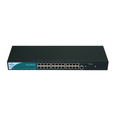
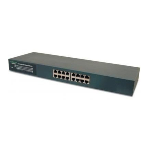
16-Port 10/100M Ethernet Rack-
Mount Smart Switch
Users Guide
#471816DFS000
www.surecom-net.com
EP-816DX-FS
All manuals and user guides at all-guides.com
all-guides.com
1 2
Full/Half-Duplex
This Switch is ideal for deployment with multiple high-speed servers for
sharing bandwidth 100Mbps or 10Mbps workgroups. In 200Mbps full-
duplex mode, any port can provide workstations with a congestion-free
data pipe for simultaneous access to the server. As all ports support
200Mbps full-duplex, it can be cascaded from any port and to any number
of switches.
Store-and-Forward Scheme
This Switch combines dynamic memory allocation with store-and-for-
ward switching to ensure that the buffer is effectively allocated for each
port while controlling the data flow between the transmit and receive
nodes to guarantee against all possible packet loss.
Introduction
The 16-Port 10/100M Ethernet Rack-Mount Smart Switch is the
latest design in its Smart Switches series for easy installation
and high-performance in an environment where traffic on the
network and the number of users increase continuously. What makes
the 16-Port 10/100M Ethernet Rack-Mount Smart Switch stand
out from the crowd is its built-in VLAN and Trunk configuration.
With VLAN, stations on different network segments can be
grouped into the same LAN segment. The goal of VLANs is to
allow for complete mobility of workstation placement, yet
keeping broadcast traffic to a minimum. When port of a
VLAN, the port will only communicate with other ports in the
VLAN. This offers a high degree of security within the netw-
ork. With Trunk, the backbone bandwidth can be increased to
advance the network performance by easing and smoothing tr-
affic load at peak hours. Small businesses and corporate branch
offices can take full advantage of 100Mbps Fast Ethernet perf-
ormance and preserve existing desktop investment with no cha-
nges required to PCs, NICs, cabling, drivers, or PC configurations.
Upgrade
This Switch offers you a simple way to increase Ethernet LAN performance
at a very low per-port cost, letting you migrate power users to high-
performance switched ports. Ethernet workgroups can upgrade to Fast
Ethernet without needing to reconfigure the network. It is an unmanaged
100/10Mbps Fast Ethernet Switch that offers solutions in accelerating
small Ethernet workgroups bandwidths.
All manuals and user guides at all-guides.com
Performance Highlights
Provides Back-pressure in half-duplex and flow control in full-duplex
Store-and-forward switching scheme capability supports rate
adaptation and ensures data integrity
N-way Auto-negotiation on each RJ-45 port. This allows for
auto-sensing of speed (100/10Mbps) and auto-detecting mode
(Full-Duplex or Half-Duplex) thereby providing you with aut-
omatic and flexible solutions in your network connections
Auto-polarity detection for correction of incorrect polarity
on the received twisted-pair on each port
Data forwarding rate 148,800 pps per port at 100% of wire-
speed
Data filtering rate eliminates all error packets, runts, etc. at
148,800pps per port at 100% of wire-speed
Supports TP interface Auto MDIX function for auto TX/RX
Swap
Package Contents
One 16-Port 10/100M Ethernet Rack-Mount Smart Switch
One Power Cord
One Users Guide
Note: If any item is damaged or missing, please contact
your supplier.
3
All manuals and user guides at all-guides.com
54
Front Panel
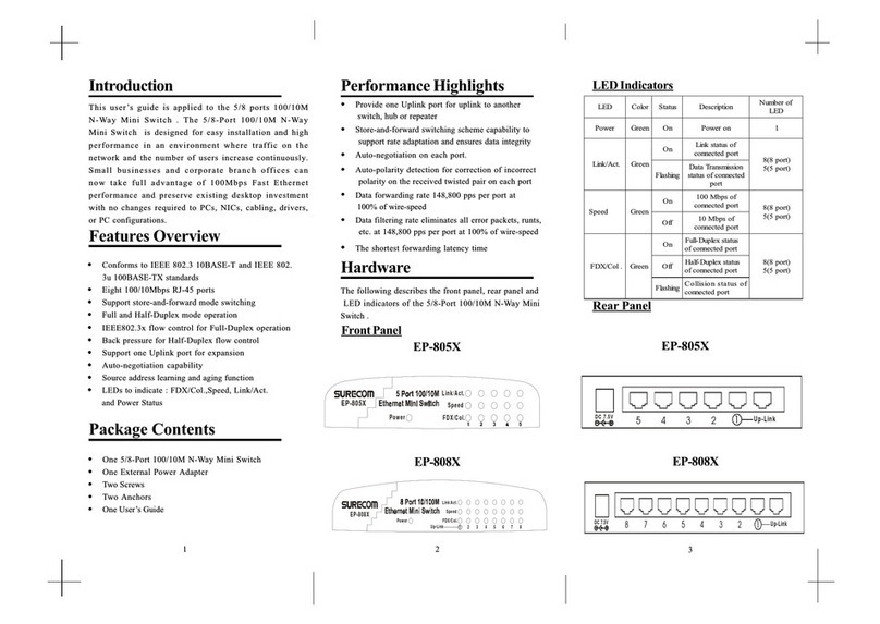
Following describes the front panel, LED indicators, and rear panel of the
Switch.
Rear Panel
Conforms to IEEE 802.3 10BASE-T,IEEE 802.3u 100BASE-TX/FX, and
IEEE 802.3x Flow control for full-duplex standards
Supports store-and-forward mode switching
Support TP interface Auto MDIX function for auto TX/RX Swap
Back pressure in half-duplex and flow control in full-duplex
Sixteen 10/100Mbps RJ-45 ports
Full and Half-Duplex mode operation on all ports
Auto-negotiation capability
Source address learning and aging function
LEDs to indicate Power, Link/Act, FDX/Col, and
100(10/100Mbps)status
Key Features
Hardware
The LED indicators of the Switch include Power, Link/Act (Link Activity),
FDX/COL. (Full-Duplex/Collision) and 100.
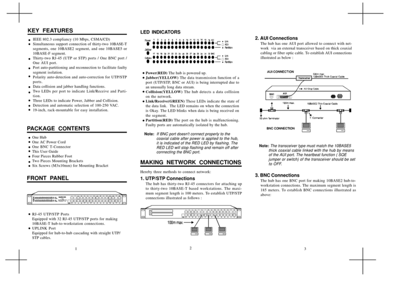
1. Power
This indicator operates when the Switch is turned on. If this indictor is
not lit, check the DC power connector to ensure proper insertion of the
power cord and that the power switch is turned ON.
2. Link/Act
These LED indicators are lighted up when there is a secure connection (or
link) to a device at any of the ports. The LED indicators blink whenever there
is reception or transmission (i.e. Activity/ACT.) of data occurring at a
port.
3. FDX/Col
This LED indicator is lighted up when a respective port is in full-du-
plex (FDX) mode.Otherwise, it is OFF for half-duplex (HDX)
operations. It blinks when collisions are occurring on the respective
port.
4. 100
This LED lights when the transmission rate is 100Mbps. It is OFF when
the transmission rate is 10Mbps or no linking.
LED Indicators
EP-816DX-FS
96~ 264VAC
47~ 63Hz
EP-816DX-FS
1234 5678
9 101112 13 14 15 16
The front Panel consist of 16 10/100M RJ-45 ports,one fiber port
and 16 port LED indicators.
The rear Panel consist of one power port.
Fiber Module
EP-816DX-FS
Console
All manuals and user guides at all-guides.com
6 7
Following describes how to connect this Switch to your Fast Ethernet
network.
Switch to PC
A PC can be connected to the Switch via a twisted-pair Category 3, 4, 5
UTP /STP straight cable or crossover cable. The PC (equipped with a RJ-
45 10/100Mbps jack) should be connected to any of sixteen ports.
The LED indicators for PC connection are dependant on the LAN card
capabilities. If LED indicators are not illuminated after making a proper
connection, check the PC LAN card, the cable, Switch conditions and
connections.
The following are LED indicator possibilities for a PC to Switch
connection:
1. The Link/ACT. LED indicator illuminates upon hookup.
2. The FDX/COL. LED indicator depends upon LAN card capabilities.
3. The 100 LED indicator comes on for a 100 Mbps and stays off
for 10Mbps.
Network Connections Switch to Hub
A hub (10BASE-T or 100BASE-TX) can be connected to the Switch via
a twisted-pair Category 3, 4, 5 UTP/STP straight cable or crossover
cable. The connection is accomplished from the any port to any port of
the connected hub.
1234 5678
9 101112 13 14 15 16
1234 5678
9 101112 13 14 15 16
RJ-45 JACK
Hub
EP-816DX-FS
EP-816DX-FS
Fiber Module
Fiber Module
Console
Console
All manuals and user guides at all-guides.com
FCC Statement
This equipment can generate, use and radiate radio frequency energy
and, if not installed and used in accordance with the instructions in this
guide, may cause interference to radio communications. This equip-
ment has been tested and found to comply with the limits for a Class A
computing device pursuant to Subpart J of Part 15 of the FCC rules,
which are designed to provide reasonable protection against radio
interference when operated in a commercial environment. Operation
of this equipment in a residential area is likely to cause interference, in
which case the user, at his own expense, will be required to take
whatever measures are necessary to correct the interference.
CE Declaration of conformity
This equipment complies with the requirements relating to electromag-
netic compatibility, EN 55022 class A for ITE and EN 50082-1. This
meets the essential protection requirements of the European Council
Directive 89/336/EEC on the approximation of the laws of the Member
States relating to electromagnetic compatibility.
Trademarks
All company, brand, and product names are trademarks or registered
trademarks of their respective companies.
All manuals and user guides at all-guides.com
all-guides.com
9
Switch to Switch (Other Devices)
The Switch can be connected to another switch or other devices (routers,
bridges, etc.) via a twisted-pair Category 3, 4, 5 UTP/STP straight or
crossover cable.
100/10M SWITCH B
100/10M SWITCH A
Crossover Cable
/Straight Cable
Crossover Cable
/Straight Cable
Technical Specifications
SF-XD618-PE
sdradnatS tenrehtET-ESAB013.208EEEI
tenrehtEtsaFXF/XT-ESAB001u3.208EEEI
noitaitogen-otuayaW-N3.208dtSEEEI/ISNA
tnerapsnarT:sepytemarF3.208EEEI
xelpuD-lluFroflortnocwolfx3.208EEEI
xelpuD-flaHroflortnocwolferusserPkcaB
LocotroP DC/AMSC
ygolopoT ratS
noissimsnarT
dohteM
drawroF-dna-erotS
:etaRrefsnarT
:tenrehtE
tenrehtEtsaF
)xelpuD-lluF(M02;)xelpuD-flaH(M01
)xelpuD-lluF(M002;)xelpuD-flaH(M001
aideM
:T-ESAB01
:XT-ESAB001
:XF-ESAB001
;)m001htgnelelbac.xaM(5,4,3.taCPTU
;)m001htgnelelbac.xaM(5.taCPTU
citporebifedom-itlumnorcim521/5.26,05
citporebifedom-elgnisnorcim521/9,8
stroPfo.oN stroP54-JRspbM01/00161
gnisuoH
lairetaM
norI
reffuBMAR ecivedrepstibM1latoT
sserddACAM
elbaT
ecivedrepseirtneK2
tekcaP
-rawroF/gniretliF
etaRgnid
)spbM01&spbM001rof(troprepdeepseriW
rewoP )CDA5/V3.3(zH36-74,V462-69CA
noitpmusnoC W8
:erutarepmeT
:gnitarepO
:egarotS
0
0
54~
O
C
0
0
06~
O
C
:ytidimuH
:gnitarepO
:egarotS
%09~%01
%59~%5
ecnamrofnoC AssalCkraMEC,AssalCCCF
8
1234 5678
9 101112 13 14 15 16
EP-816DX-FS
If you want to use Fiber, you have to cancel Jump on Fiber Board.
And you have to set Fiber mode by software.
Fiber Module
Console
All manuals and user guides at all-guides.com
Console management setup
In this chapter, you will be provided with detailed information on how to
set up the EP-816DX-FS through a PC terminal emulation program. A
terminal program is required to communicate with the Switchs internal
software. Only after the terminal program setup is done, you are thus able
to proceed to set up the EP-816DX-FS.
Before you are able to access the EP-816DX-FS,you have to
configure your terminal emulation program. Windows 95/98
provide a suitable program called Hyper Terminal for config-
uration, or you can choose other third-party products such as
Telix and ProCom instead.
Connect a normal RS-232C Serial DB9 Cable to a COM port on your PC
and to the console port of your Smart Switch as the below figure.
This section describes how to set up the terminal emulation program by using
Windows 95/98 Hyper Terminal.
1. Press Start on the Taskbar then click on Programs to bring up the
following icons. Double click the Hyper Terminal icon.
2. From the Hyper Terminal screen, double click on the Hypertrm.exe icon.
10 11
EP-816DX-FS
1234 5678
9101112 13 14 15 16
Console
Fiber Module
Comport
RS232 transfer RJ45
RJ45 Cable
All manuals and user guides at all-guides.com
3. The Connection Description Screen is displayed. Type whatever
you like in the Name panel to identify the connection, choose a icon
below  Name panel and click OK.
4. Since you wont dial out via a modem, you only need to set the Com
port. Select the available Com port (usually COM2, since a mouse is
usually connected to COM1) from the Connecting using label and press
the Enter key.
5. This COM2 properties settings must be mandatory correct.
Follow the instructions as shown to complete the settings and click
OK.
6. Select Properties item from File Menu.
12 13
All manuals and user guides at all-guides.com
7. Click on the Setting tab. Select ANSI (or ANSIW) from
the Emulation label then click OK.
The Hyper Terminal set-up has been finished yet. Now you are
ready for the EP-816DX-FS setup.
14
All manuals and user guides at all-guides.com
1.Power Up
Here we can see a lot of message shown in this power-on screen. As the
title described on first line, this is a Self-diagnostic process running during
power-on stage. First part of this page is title and version information.
Following are Eeprom test item and result lists for system components. If
hardware test is fail during this stage, be sure to contact sales for more de-
tailed test. Device operating under abnormal condition will cause un-predic-
ted result.
No matter the test result is successful or fail, you are always requested to
press <Enter> to enter next stage.
2.Log in
Log-in is required to access the command console. A password is used to
provide the basic security control. The factory default password is admin.
The user can change password once in the System menu. If the password is
forgotten, user must return this device to sales or agent for SW mainten-
ance. In this log-in screen, input the correct password and press enter
will lead user to main menu.
This is a very straight forward request for Password. Without valid pass-
word, user cannot monitor the system status or set special functions from
this interface.
3.Main Menu
15 16
All manuals and user guides at all-guides.com
all-guides.com
The main menu is the top level of menu-driven screen. All functions are
selected from this screen.
You can press 1 ~ 6 number key to the choice Function.
You always can press <Q> to abort input or Return,except when you are
input new password.
Main function item Description:
(1)System Base configuration
Collision 16 times will drop packet /Aging / Replace PVID / Trunk
Port
(2)Port configuration Setting
Auto-Negotiation / Speed / Duplex / Flow_Contro
VLAN-Tag/unTag / AUTO-Crossover / Port_locking / Fiber
TOS Over VLAN Priority / Port-Base priority
(3)PortBase VLAN /PVID VLAN Setting
PortBase VLAN / PortBase VLAN ID (PVID) VLAN
(Members in trunk should be in the same VLAN)
(4)Priority Setting
Port-Base / TOS / VLAN
(5)PVID Port ID Setting
PVID Port ID
(6)Load Default Setting & Password
Change Password / load default / Reset Switch
Load default: clear current setting and load default setting.
Restart Switch : SW re-boot.
4.System Base Configuration
How to set Trunk and Aging?
Most switch selections are toggles. Here you can press the No.1 -No.8
bottom to change selectionss situation.
The switch has chip 1 and chip 2.
The 1th-4th and 9th-12th port use chip 1. The 5th-8th and 13th-16th
port use chip 2.
1.Setting Trunk port:
Trunk port has a group of two ports. The 4th and 12th port are chip 1.
The 8th and 16th port are chip 2.
2.Setting Aging function:
Aging Time value is default 300 second.
Note:About the setting of the switch later, all like this port . But just for
separate setting chip 1 and 2.
17 18
All manuals and user guides at all-guides.com
5.PortConfiguration
If you want to change port 16 for fiber or other ports. Please do as below:
1.Type <M>,then enter the port number which you want to change.
2.Please enter the port number 16.
3.You can do all functions with the number deys as below.
<1> Auto-Negotiation <2>Speed <3>Duplex <4> Pause frame
All functions are toggles.
If you want to go to next page, just press <SPACE>.
But all these only can set the functions of port 16.
4.If you want to change port 2, you have to press <Q> first, and type <M>
second.
Then please repeat step 2 again.
5. After all ports are set,must type <Enter> key to save.
Then press SPACE key to the window on the next page.
Type 1 make Auto negotiation to Disable.
19 20
If you enable the locking function,the switch will lock the first MAC
address in learning table. So you must disable aging function to prevent
MAC address to be dropped after 300 second. When this port does not send
packet.
Note:Lock function
All manuals and user guides at all-guides.com
Type the 4 key.
6.VLAN Configuration
How to set Port Base VLAN and PVID VLAN?
Switch provides two kinds of VLAN:(1) PortBase VLAN(2) PVID VLAN
1.PortBase VLAN
How to set? Please do as below.
(1) Main Menu (press 3)---PortBase VLAN/PVID VLAN Setting (press 1)---
PortBase VLAN menu.
Because switchs default value is PortBase VLAN, so dont press V to
change VLAN mode.
(2) If you want to set Concentration mode in this switch , you can use the
PortBase VLAN easily to get you want.
Note:The Tag/UNTag function and PVID ID setting will not be modified
when you Let the Switch be in PortBase VLAN mode.
The packet will be forwarded by Switch,and Switch will ignore any
VLAN information.
Example: As below,they cant communicate to each other from the 1th
to 8th port,but each of them can communicate to the 9th port.
VLAN mode
21 22
All manuals and user guides at all-guides.com
2.As this example,we use Group way to fix the vlan table by pressing <H>.
3.Look at Group 0. Group 0 has the 1th and 9th port. How can we
add the 1th and 9th port in Group 0? Please do as below.
4.Selecting the port that you want to add in the group.
How to change the setting of PortBase VLAN?
1.Type <M>. Selecting the input mode base on <V> Port <H> Group (
V---vertical , H---horizontal)
23 24
5.
The 1th port become O in Group 00.
Also we can press 9 then Enter. The 9th port is added in the
Group 00.
Because all selections are toggles. So if we want to select the 1th or
9th port again, the port have to be out of the group again.
The 1th to 9th ports are together. We can type 1 the Enter.
After you set that above, the item will be ofrom x.
All manuals and user guides at all-guides.com
2.PVID VLAN
The switch will use the last 4 bits of the VID when VLAN Tag is in the PVID
mode.If the packet has Tag,it will accord to PVID table to forward the packet.
Note: The Switch can only set one kind of VLAN mode. If you want to
change VLAN mode,you have to press <V> . Then set and save on
VLAN list.The VLAN mode of this switch have changed.However,if
you just press VLAN mode,then go back to main menu.The VLAN mode
of this switch havent changed.
The setting of PVID VLAN table is like PortBase VLAN.
For following Table
The port 1,2,3 all can communicate by VID =0 of VLAN packet. Also
the port 2,4 can use VID =1 to communicate to each other. When you send
a VLAN packet of VID =2 ~ 15 to port 1,the packet will be dropped. Because
of the switch will check table 2 ~ 15,but port 1 does not include in table
2 ~15.
If you send a normal packet to the Switch,it will tag a VID. Then it will
forward the packet in VLAN table.(Please refer to PVID<P.29>.)
Before enter into PVID VLAN , please be sure what kind of VLAN mode where
the switch in. If the switch is not in PVID VLAN mode , please type <V> then
<2> in VLAN configuration. And press <2> again to go into PVID VLAN
configuration.
25 26
6.When all setting are finished , please type <Q> to go out. Then repeat
the 3th to 6th step to finish group 00-07.
7.Right now, please press Enter to save.
If you send a VID = 0 packet into port 1, the switch will check the PVID 00
table first at the same time. According to the table above,it can forward this
packet to port 2,3. When port 2,3 have not been learned by Switch.
Note:PVID table ,port VID and Tag/unTag effect PVID VLAN solution.
The fifth point of Main Menu has setting function of every ports
VID.
All manuals and user guides at all-guides.com
all-guides.com
7. How to setting priority
The Switch not only handle with data packets but also provide service of
multimedia data. Switch provides four priority queues on each port at fixed
8:4:2:1 rate.
By port base:
Set specific port at specific queue.Switch only check the port pri-
ority and not check VLAN and TOS.
By VLAN first:
Switch check VLAN three priority bit first then TOS priority.If
you want to set VLAN priority. Please do not enable PortBase and
TOS priority. It is a default setting.
By IP TOS first
Switch check IP TOS three bit first then VLAN three bits.
Note:
The priority function setting is placed in port configuration.
Right now , please type <2> and two times <SPACE> to the function.
Just press <4> on main menu
(1)PortBase priority :
Example:If you want to change the 1th port to make its priority to be
the highest(the 3th Queue).
Type <1>--<M>--enter <1>(Please chose the port number you want to
set.)--enter <03>(Please chose the queue is used by port 1)--type <Q>--
press <Enter> to save --press <Q>
(2)TOS priority:
There are two chips in the switch. The first chip manages the 1th to
4th port and 9th to 12th port.
The second chip manages the 5th to 8th port and 13th to 16th port.
According to the 0th to 3th Queue,we can distribute IP Priority to the
highest or lowest priority.
And the 0th Queue is the lowest Queue. The 3th Queue is the highest Queue.
27 28
All manuals and user guides at all-guides.com
(2)VLAN priority:
The setting is just like TOS.
Note: If the switch is on PortBase VLAN mode. VLAN Priority doesnt
have any using.
8.PVID
How to set the VLAN ID for each port?
If you want to set the 1th ports VID to be 1.
Type <5>on main menu--<M>--enter <01>--type <Enter>--
<01>(VLAN ID)--type <Enter>--<Q>-- type <Enter> (for saving)
Note:Switch can change VID under PVID VLAN mode only.
30
Example:If we want to change the IP Priority 00 of chip 1.
Make IP Priority 00 to be the highest priority.
Press <2>--<M>--<1>(Please chose the chip you want to set.)--<Enter>--
<00>(Please chose the TOS priority you want to change.)
--<Enter>--<03>(Its the queue number that TOS priority 00 uses.)--
<Enter> for saving --<Q>
Queue number
29
After you set that as
above, the number will
be 03 from 00.
1. When you send a normal pocket to switch,the switch will add that ports
VID.(in PVID VLAN mode)
2. Because all ports VID are 01. So when we send normal packet to switch,
the switch will refer to the table of VID=01 in PVID VLAN table.
3. As the setting of the windows above,each switchs port can data in-
formation to each other.
4. If the packet is sent out of tag port,then it will be added VLAN tag of
VID=01.
All manuals and user guides at all-guides.com
9. Load Default and Change Password
1.Change password:
Type <6> on main menu--<1>--enter the new password--<Y>
2.Load default
Type <6> on main menu--<2>--<Enter>--<Y>
Factory Default is used to reload the manufacturers defaults. The settings
are exactly the same as the one that come with the Smart Switch originally.
Factory Default will reload the defaults into EEPROM and make the update
take effect immediately.
3.Reset Switch:
Type <6> on main menu--<3>--<Enter>--<Y>
Note:Please do Reset Switch again after every setting of the switch. This
can make settings are work.
Note:PVID table ,port VID and Tag/unTag effect PVID VLAN solution.
31
All manuals and user guides at all-guides.com

Other manuals for EP-816DX-FS

2

Other Surecom Switch manuals

Surecom 824DXFS2B User manual

Surecom

Surecom 824DXFS2B User manual

Surecom EP-804CG User manual

Surecom

Surecom EP-804CG User manual

Surecom EP-804CG-S User manual

Surecom

Surecom EP-804CG-S User manual

Surecom EP-816DX-FS User manual

Surecom

Surecom EP-816DX-FS User manual

Surecom EP-824DX-B User manual

Surecom

Surecom EP-824DX-B User manual

Surecom EP-516DX-T User manual

Surecom

Surecom EP-516DX-T User manual

Surecom EP-505ST User manual

Surecom

Surecom EP-505ST User manual

Surecom EP-824DX-FS User manual

Surecom

Surecom EP-824DX-FS User manual

Surecom EP-816X User manual

Surecom

Surecom EP-816X User manual

Surecom EP-517T User manual

Surecom

Surecom EP-517T User manual

Surecom EP-816DX-FS User manual

Surecom

Surecom EP-816DX-FS User manual

Surecom EP-508 User manual

Surecom

Surecom EP-508 User manual

Surecom EP-824DX User manual

Surecom

Surecom EP-824DX User manual

Surecom EP-816DX-FW User manual

Surecom

Surecom EP-816DX-FW User manual

Surecom EP-824DX-FS User manual

Surecom

Surecom EP-824DX-FS User manual

Surecom EP-802X User manual

Surecom

Surecom EP-802X User manual

Surecom EP-816DX-AS User manual

Surecom

Surecom EP-816DX-AS User manual

Surecom EX-516DX-T User manual

Surecom

Surecom EX-516DX-T User manual

Surecom EP-726DG User manual

Surecom

Surecom EP-726DG User manual

Surecom EP-716X User manual

Surecom

Surecom EP-716X User manual

Surecom EP-824DX-CS User manual

Surecom

Surecom EP-824DX-CS User manual

Surecom EP-805X User manual

Surecom

Surecom EP-805X User manual

Surecom EP532D User manual

Surecom

Surecom EP532D User manual

Surecom EP-808DG-S User manual

Surecom

Surecom EP-808DG-S User manual

Popular Switch manuals by other brands

Multico EW-K1302DPC4K Quick installation guide

Multico

Multico EW-K1302DPC4K Quick installation guide

Altuscn KH1508 user manual

Altuscn

Altuscn KH1508 user manual

CTC Union JB230 Series product manual

CTC Union

CTC Union JB230 Series product manual

Avaya C460 SMON quick start guide

Avaya

Avaya C460 SMON quick start guide

Fujitsu XG2000CR Hardware guide

Fujitsu

Fujitsu XG2000CR Hardware guide

Beckett 1502R8 manual

Beckett

Beckett 1502R8 manual

Avocent SwitchView Quick installation guide

Avocent

Avocent SwitchView Quick installation guide

Avaya Ethernet Routing Switch 8300 Installation

Avaya

Avaya Ethernet Routing Switch 8300 Installation

schmersal AZM300B-ST-1P2P instructions

schmersal

schmersal AZM300B-ST-1P2P instructions

Morrell SW-UNM-8FE user manual

Morrell

Morrell SW-UNM-8FE user manual

HPE 12500 Series Command reference

HPE

HPE 12500 Series Command reference

Transition Networks SM24DP4XA install guide

Transition Networks

Transition Networks SM24DP4XA install guide

SignaMax 065-7528 user guide

SignaMax

SignaMax 065-7528 user guide

Amperes SQ9815 instruction manual

Amperes

Amperes SQ9815 instruction manual

AMX Enova AVX-400 Operation/reference guide

AMX

AMX Enova AVX-400 Operation/reference guide

Agilent Technologies Agilent 3499A Quick reference guide

Agilent Technologies

Agilent Technologies Agilent 3499A Quick reference guide

ATEN KL9116 user manual

ATEN

ATEN KL9116 user manual

DSPPA PC1010H user manual

DSPPA

DSPPA PC1010H user manual

manuals.online logo
manuals.online logoBrands
  • About & Mission
  • Contact us
  • Privacy Policy
  • Terms and Conditions

Copyright 2025 Manuals.Online. All Rights Reserved.