SureStep STP-DRV-4035 Quick start guide

3
3
3
SureSteptM
Stp-DRV-4035
MicRoStepping DRiVe
Chapter
Chapter
Chapter
In This Chapter...
Features � � � � � � � � � � � � � � � � � � � � � � � � � � � � � � � � � � � � � � � �3–2
Specifications � � � � � � � � � � � � � � � � � � � � � � � � � � � � � � � � � � � �3–3
Typical Wiring Diagram � � � � � � � � � � � � � � � � � � � � � � � � � � � �3–4
Connection and Adjustment Locations � � � � � � � � � � � � � � � � �3–4
Connecting the Motor� � � � � � � � � � � � � � � � � � � � � � � � � � � � � � � � �3–5
Connecting the Power Supply � � � � � � � � � � � � � � � � � � � � � � � � � � �3–6
Connecting the Logic � � � � � � � � � � � � � � � � � � � � � � � � � � � � � � � � �3–7
Using Logic That is Not 5 volt TTL Level � � � � � � � � � � � � � � � � � � �3–9
The Enable Input � � � � � � � � � � � � � � � � � � � � � � � � � � � � � � � � �3–9
Setting Phase Current� � � � � � � � � � � � � � � � � � � � � � � � � � � � � 3–10
Current Setting Formula � � � � � � � � � � � � � � � � � � � � � � � � � � � � � �3–10
Current Setting Table � � � � � � � � � � � � � � � � � � � � � � � � � � � � � � � �3–11
Microstepping � � � � � � � � � � � � � � � � � � � � � � � � � � � � � � � � � �3–12
Idle Current Reduction � � � � � � � � � � � � � � � � � � � � � � � � � � � �3–13
Self Test � � � � � � � � � � � � � � � � � � � � � � � � � � � � � � � � � � � � � � � 3–13
Dimensions� � � � � � � � � � � � � � � � � � � � � � � � � � � � � � � � � � � � �3–15

Chapter 3: SureStepTM STP-DRV-4035 Microstepping Drive
SureStepTM Stepping Systems User Manual
3–2 5th Ed., Rev. B 01/2019
Features
• Drives sizes 17 through 34 step motors
• Pulse width modulation, MOSFET 3 state switching amplifiers
• Phase current from 0.4 to 3.5 amps (switch selectable, 32 settings)
• Optically isolated step, direction and enable inputs
• Half, 1/5, 1/10, 1/50 step (switch selectable)
• Automatic 50% idle current reduction (can be switched off)
Block Diagram
Optical
Isolation
Step+
V+
V–
Step– A+
A–
B+
B–
Dir+
Dir–
Enable+
Enable–
Microstep
Sequencer
Current
0.4 to 3.5
A/Phase
Steps/Rev:
1/2, 1/5,
1/10 or 1/50
50% Idle
Current Reduction
Self Test
MOSFET
Amplifier
Logic Connections
from PLC or Indexer
Connections
to Bipolar
Step Motor
Connect to
Power Supply
(12 - 42 VDC)
STP-DRV-4035

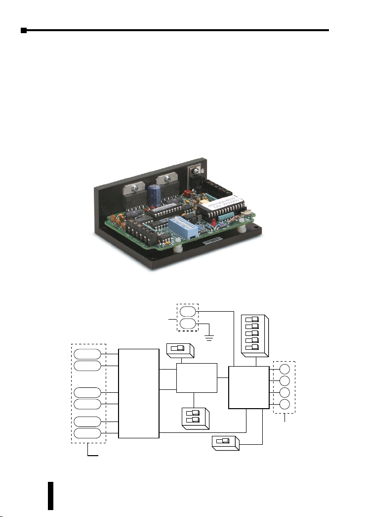
SureStepTM Stepping Systems User Manual 3–3
Chapter 3: SureStepTM STP-DRV-4035 Microstepping Drive
5th Ed., Rev. B 01/2019
Specifications
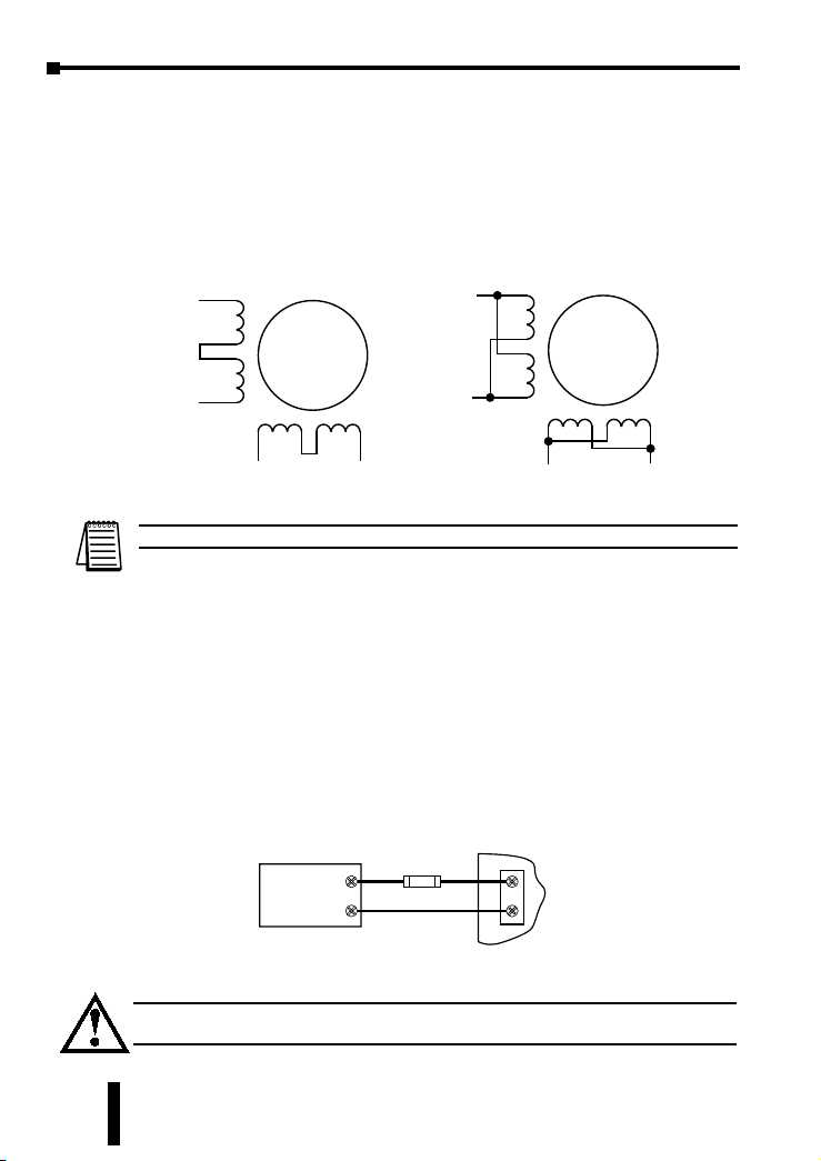
Note: The STP-DRV-4035 Microstepping Drive works with 4, 6, and 8 lead bipolar step
motors. All AutomAtionDirect SureStep™ motors are four-lead bipolar step motors.
SureStep™ Microstepping Drives Specifications
Part Number STP-DRV-4035
Input Power
(with red Power On LED) 12-42 VDC (including ripple voltage)
Output Power Output current selectable from 0.4 to 3.5 Amps/phase motor current
(maximum output power is 140 W)
Current Controller Dual H-bridge Bipolar Chopper
(4-state 20 kHz PWM with MOSFET switches)
Input
Signals
Input Signal
Circuit
Opto-coupler input with 440 Ohm resistance (5 to 15 mA input current),
Logic Low is input pulled to 0.8 VDC or less, Logic High is input 4VDC or
higher (see page 3-9 for using input voltages higher than 5VDC)
Pulse Signal Motor steps on falling edge of pulse and minimum pulse width
is 0.5 microseconds
Direction
Signal
Needs to change at least 2 microseconds before a step pulse is sent. CW
and CCW are viewed from the end opposite the drive end of the motor
(looking out of the shaft).
Enable Signal Logic 1 will disable current to the motor
(current is enabled with no hook-up or logic 0)
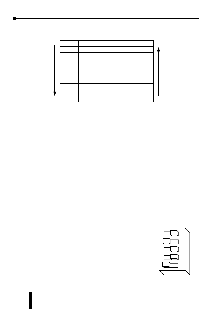
DIP Switch
Selectable
Functions
Self Test Off or On (uses half-step to rotate 1/2 revolution in each direction
at 100 steps/second)
Microstepping 400 (200x2), 1,000 (200x5), 2,000 (200x10), or 10,000 (200x50) steps/rev
Idle Current
Reduction
0% or 50% reduction (idle current setting is active if motor is at rest
for 1 second or more)
Phase Current
Setting 0.4 to 3.5 Amps/phase with 32 selectable levels
Drive Cooling Method Natural convection (mount drive to metal surface if possible)
Dimensions 3 x 4 x 1.5 inches [76.2 x 101.6 x 38.1 mm]
Mounting Use #4 screws to mount on wide side (4 screws) or narrow side (2 screws)
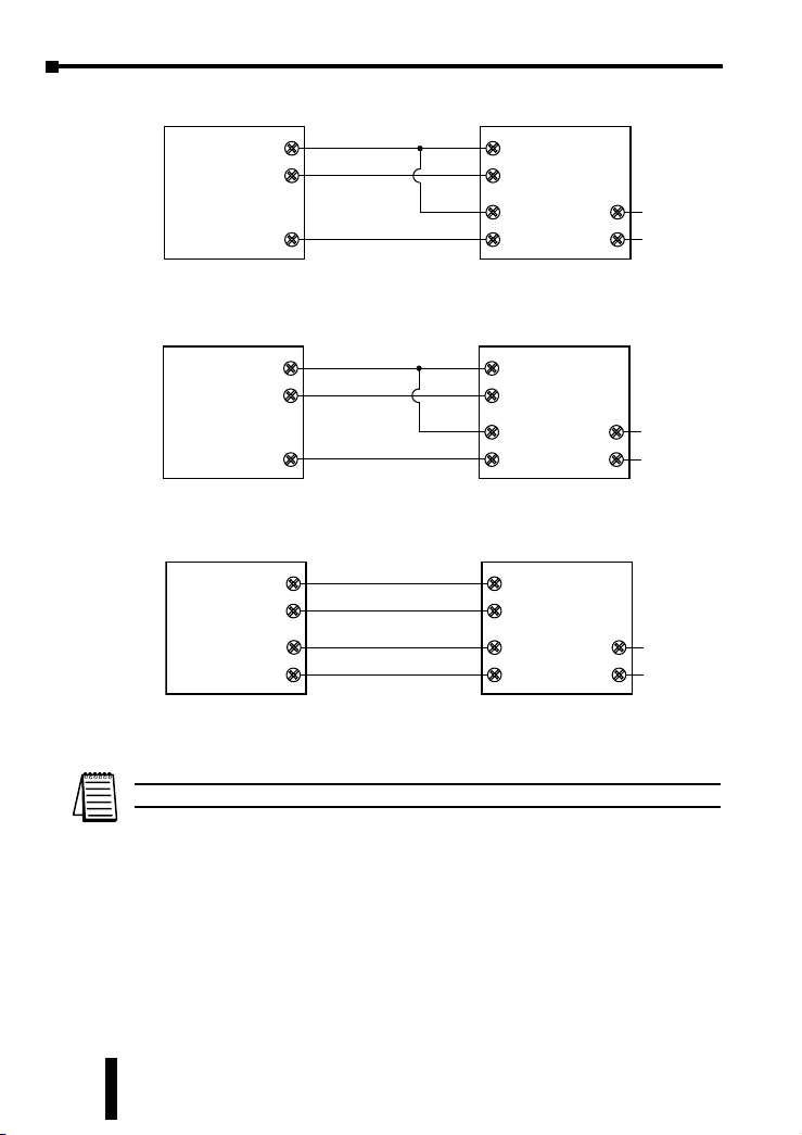
Connectors Screw terminal blocks with AWG 18 maximum wire size
Weight 9.3 oz. [264g]
Storage Temperature -20–80 °C [-4–176 °F]
Chassis Operating
Temperature
0–55 °C [32–131 °F] recommended; 70 °C [158 °F] maximum
(use fan cooling if necessary); 90% non-condensing maximum humidity
Agency Approvals CE

Chapter 3: SureStepTM STP-DRV-4035 Microstepping Drive
SureStepTM Stepping Systems User Manual
3–4 5th Ed., Rev. B 01/2019
Typical Wiring Diagram
Connection and Adjustment Locations
The diagram below shows where to find the important connection and adjustment
points.
Logic
Connector
(STEP+/-, DIR+/-, EN+/-)
Mounting
Hole (1 of 6)
Power
Connector
Motor
Connector
Switches for
Selecting Current,
Step Resolution,
Current Reduction
and Self Test
Power On
LED
VDC +
STP-
DRV-4035
Step Motor
Power Supply
–
+
Stepper Drive
VDC –
A +
A –
B +
B –
Step Motor
STP-MTRx
Red
White
Green
Black
A+
A–
B+
B–
Cable Color Code
STP-PWR-3204
1
2
3
4
WireTe rm Pin #
Motor
Power
35 VDC
Logic
Power
5VDC
STP-DRV-4035
Typical Wiring
Diagram
12" Motor Pigtail
with Connector
Extension Cable
with Connector
STP-EXTx

SureStepTM Stepping Systems User Manual 3–5
Chapter 3: SureStepTM STP-DRV-4035 Microstepping Drive
5th Ed., Rev. B 01/2019
Connecting the Motor
Warning: When connecting a step motor to the SureStep™ STP-DRV-4035
microstepping drive, be sure that the motor power supply is switched off. When using
a motor not supplied by automationDirect, secure any unused motor leads so that they
can’t short out to anything. Never disconnect the motor while the drive is powered up.
Never connect motor leads to ground or to a power supply. (See the Typical Wiring
Diagram shown on page 2-4 of this chapter for the step motor lead color code of
automationDirect supplied motors.)
You must now decide how to connect
your stepping motor to the SureStepTM
STP-DRV-4035 microstepping drive.
Four Lead Motors
Four lead motors can only be connected
one way. Please follow the wiring
diagram shown to the right.
Note: All AutomAtionDirect SureStep™
motors are four lead bipolar step motors.
Six Lead Motors
Six lead motors can be connected in series or center tap. In series mode, motors
produce more torque at low speeds, but cannot run as fast as in the center tap
configuration. In series operation, the motor should be operated at 30% less than
rated current to prevent overheating. Wiring diagrams for both connection methods
are shown below. NC means not connected to anything.
Note: Be aware that step motor wire lead colors vary from one manufacturer to another.
A+
A–
B+ B–
4
lead
motor
Red
White
Green Blac
k
4 Leads
A+
A–
NC
B+B– NC
6
lead
motor
Red Black Red
/
Wht
Green
Grn/Wht
White
6 Leads Series Connected
A+
A–
NC
B+B– NC
6
lead
motor
Grn/Wht
White
Green
Red
Red/
Wht
Black
6 Leads Center Tap Connected

Chapter 3: SureStepTM STP-DRV-4035 Microstepping Drive
SureStepTM Stepping Systems User Manual
3–6 5th Ed., Rev. B 01/2019
Eight Lead Motors
Eight lead motors can also be connected in two ways: series or parallel. Series
operation gives you more torque at low speeds and less torque at high speeds.
When using series connection, the motor should be operated at 30% less than the
rated current to prevent over heating. Parallel operation allows a greater torque at
high speed. When using parallel connection, the current can be increased by 30%
above rated current. Care should be taken in either case to assure the motor is not
being overheated. The wiring diagrams for eight lead motors are shown below.
Note: Be aware that step motor wire lead colors vary from one manufacturer to another.
Connecting the Power Supply
The STP-PWR-3204 power supply from automationDirect is the best choice to
power the step motor drive. If you need information about choosing a different
power supply, please read the section titled “Choosing a Power Supply” in Chapter
7: “SureStep System Power Supplies”.
If your power supply does not have a fuse on the output or some kind of short circuit
current limiting feature you need to put a 4 amp fast acting fuse between the drive
and power supply. Install the fuse on the + power supply lead.
Connect the motor power supply “+” terminal to the driver terminal labeled “+
VDC”. Connect power supply “-” to the drive terminal labeled “VDC-”. Use no
smaller than 18 gauge wire. Be careful not to reverse the wires. Reverse connection
will destroy your drive and void the warranty.
A+
A–
B+ B–
8
lead
motor
8 Leads Series Connected
Orange
Org/Wht
Blk/Wht
Black
Red Red/
Wht
Yel/
Wht
Yellow
8 Leads Parallel Connected
A+
A–
B+ B–
8
lead
motor
Orange
Org/
Wht
Blk/
Wht
Black
Red
Red/
Wht
Yel/
Wht
Yellow
VDC
Step Motor
Power Supply
12 - 42 VDC
+
–
Fuse *
+–
* External fuse not required when using an
STP-PWR-3204 P/S; fuse is internal.
Do NOT use STP-PWR-48xx or -70xx power supplies with an STP-DRV-4035 drive,
because those power supplies exceed the voltage limit of this drive.

SureStepTM Stepping Systems User Manual 3–7
Chapter 3: SureStepTM STP-DRV-4035 Microstepping Drive
5th Ed., Rev. B 01/2019
Further information about braking accessories and regeneration clamping can
be found in Appendix A and the STP-DRVA-RC-050 REGENERATION CLAMP
datasheet.
Connecting the Logic
The SureStep drive contains optical
isolation circuitry to prevent the electrical
noise inherent in switching amplifiers
from interfering with your circuits. Optical
isolation is accomplished by powering
the motor driver from a different supply
source than your control circuits. There
is no electrical connection between the
two; signal communication is achieved
by infrared light. When your circuit turns
on or turns off, an infrared LED (built
into the drive), signals a logic state to the
phototransistors that are wired to the brains
of the drive. A schematic diagram input
circuit is shown to the right.
You will need to supply a source of step pulses to the drive at the STEP+ and STEP–
terminals and a direction signal at the DIR+ and DIR– terminals, if bidirectional
rotation is required. You will also need to determine if the ENABLE input terminals
will be used in your application. Operation, voltage levels and wiring on the
ENABLE terminals is the same as the STEP and DIRECTION terminals. The EN+
and EN– terminal can be left not connected if the enable function is not required.
All logic inputs can be controlled by a DC output signal that is either sinking (NPN),
sourcing (PNP), or differential.
On the next couple of pages are examples for connecting various forms of outputs
from both indexers and PLCs.
Internal to the
STP-DRV-4035
Drive Input Circuit
220 ohms
220 ohms
STEP+
STEP–

Chapter 3: SureStepTM STP-DRV-4035 Microstepping Drive
SureStepTM Stepping Systems User Manual
3–8 5th Ed., Rev. B 01/2019
Connecting to an Indexer with Sinking Outputs
+5V OUT DIR+
DIR DIR–
STEP+
STEP STEP–
Indexer
with
Sinking
Outputs
STP-DRV-4035
Drive
EN+
EN–
N/C
N/C
Connecting to an Indexer with Sourcing Outputs
COM DIR–
DIR DIR+
STEP–
STEP STEP+
Indexer
with
Sourcing
Outputs
STP-DRV-4035
Drive
EN+
EN–
N/C
N/C
Connecting to an Indexer with Differential Outputs
DIR+ DIR+
DIR– DIR–
STEP+
STEP– STEP–
Indexer
with
Differential
Outputs
STP-DRV-4035
Drive
STEP+ EN+
EN–
N/C
N/C
Note: Many high speed indexers have differential outputs.

SureStepTM Stepping Systems User Manual 3–9
Chapter 3: SureStepTM STP-DRV-4035 Microstepping Drive
5th Ed., Rev. B 01/2019
Using Logic That is Not 5 volt TTL Level
Some step and direction signals, especially those of PLCs, don’t use 5 volt logic.
You can connect signal levels as high as 24 volts to the SureStep drive if you add
external dropping resistors to the STEP, DIR and EN inputs, as shown below.
• For 12 volt logic, add 820 ohm, 1/4 watt resistors
• For 24 volt logic, use 2200 ohm, 1/4 watt resistors
Connecting to an Indexer with Sink or Source 12-24 VDC Outputs
Connecting to a PLC with Sink or Source 12-24 VDC Outputs
Note: Most PLCs can use 24 VDC Logic.
The Enable Input
The ENABLE input allows the user to turn off the current to the motor by providing
a positive voltage between EN+ and EN-. The logic circuitry continues to operate,
so the drive “remembers” the step position even when the amplifiers are disabled.
However, the motor may move slightly when the current is removed depending on
the exact motor and load characteristics.
Note: If you have no need to disable the amplifiers, you don’t need to connect anything
to the ENABLE input.
Connecting to Indexer with 12 - 24 VDC Sinking Outputs - stretched
+12-24V DIR+
DIR DIR–
STEP+
STEP STEP–
Indexer
with
Sinking
Outputs R
R
STP-DRV-4035
Drive
EN+
EN–
R
ENABLE
(If enable function is used)
Connecting to PLC with 12 - 24 VDC Sinking Outputs - stretched
+12-24V DIR+
DIR DIR–
STEP+
STEP STEP–
PLC
with
Sinking
Outputs R
R
STP-DRV-4035
Drive
EN+
EN–
R
ENABLE
(If enable function is used)
+
–
COM 12-24 VDC
Connecting to Indexer with 12 - 24 VDC Sourcing Outputs - stretched
COM DIR–
DIR DIR+
STEP–
STEP STEP+
Indexer
with
Sourcing
Outputs R
R
STP-DRV-4035
Drive
EN–
EN+
R
ENABLE
(If enable function is used)
Connecting to PLC with 12 - 24 VDC Sourcing Outputs - stretched
COM DIR–
DIR DIR+
STEP–
STEP STEP+
PLC
with
Sourcing
Outputs R
R
STP-DRV-4035
Drive
EN–
EN+
R
ENABLE
(If enable function is used)
+–
+12-24V 12-24 VDC

Chapter 3: SureStepTM STP-DRV-4035 Microstepping Drive
SureStepTM Stepping Systems User Manual
3–10 5th Ed., Rev. B 01/2019
Setting Phase Current
Before you turn on the power supply the first time, you need to set the drive for
the proper motor phase current. The rated current is usually printed on the motor
label. The SureStep drive current is easy to set. If you wish, you can learn a simple
formula for setting current and never need the manual again. Or you can skip to the
table on the next page, find the current setting you want, and set the DIP switches
according to the picture.
Current Setting Formula
Locate the bank of tiny switches near the motor connector. Five of the switches, DIP
switch positions 5-9, have a value of current printed next to them, such as 0.1, 0.2,
0.4, 0.8 and 1.6. Each switch controls the amount of current, in amperes (A), that
its label indicates in addition to the minimum current value of 0.4 Amps. There is
always a base current of 0.4 Amps, even with all five DIP switches set to the “off”
position (away from their labels). To add to that, slide the appropriate switches
toward their labels on the PC board. You may need a small screwdriver for this.
DIP switch current total settings =
step motor required phase current – 0.4 Amps always present base current
Example
Suppose you want to set the drive for 2.2 Amps per
phase based on the step motor showing a phase
current of 2.2 Amps. You need the base current of
0.4 Amps plus another 1.6 and 0.2 Amps.
2.2 = 0.4 + 1.6 + 0.2
Slide the 1.6 and 0.2 Amp DIP switches toward the
labels as shown in the figure to the right.
Step A+ A– B+ B–
0
1
2
3
4
5
6
7
8
DIR=1
cw
DIR=0
ccw
Step 0 is the Power Up State
Step Table
(half stepping)
open
+
+
+
open
–
–
–
open
open
–
–
–
open
+
+
+
open
+
+
open
–
–
–
open
+
+
–
–
open
+
+
+
open
–
–
0.1
0.2
0.4
0.8
1.6
56789

SureStepTM Stepping Systems User Manual 3–11
Chapter 3: SureStepTM STP-DRV-4035 Microstepping Drive
5th Ed., Rev. B 01/2019
Current Setting Table
0.4
AMPS/
PHASE
0.1
0.2
0.4
0.8
1.6
0.5
AMPS/
PHASE
0.1
0.2
0.4
0.8
1.6
0.6
AMPS/
PHASE
0.1
0.2
0.4
0.8
1.6
0.7
AMPS/
PHASE
0.1
0.2
0.4
0.8
1.6
0.8
AMPS/
PHASE
0.1
0.2
0.4
0.8
1.6
0.9
AMPS/
PHASE
0.1
0.2
0.4
0.8
1.6
1.0
AMPS/
PHASE
0.1
0.2
0.4
0.8
1.6
1.1
AMPS/
PHASE
0.1
0.2
0.4
0.8
1.6
1.2
AMPS/
PHASE
0.1
0.2
0.4
0.8
1.6
1.3
AMPS/
PHASE
0.1
0.2
0.4
0.8
1.6
1.4
AMPS/
PHASE
0.1
0.2
0.4
0.8
1.6
1.5
AMPS/
PHASE
0.1
0.2
0.4
0.8
1.6
1.6
AMPS/
PHASE
0.1
0.2
0.4
0.8
1.6
1.7
AMPS/
PHASE
0.1
0.2
0.4
0.8
1.6
1.8
AMPS/
PHASE
0.1
0.2
0.4
0.8
1.6
1.9
AMPS/
PHASE
0.1
0.2
0.4
0.8
1.6
2.0
AMPS/
PHASE
0.1
0.2
0.4
0.8
1.6
2.1
AMPS/
PHASE
0.1
0.2
0.4
0.8
1.6
2.2
AMPS/
PHASE
0.1
0.2
0.4
0.8
1.6
2.3
AMPS/
PHASE
0.1
0.2
0.4
0.8
1.6
2.4
AMPS/
PHASE
0.1
0.2
0.4
0.8
1.6
2.5
AMPS/
PHASE
0.1
0.2
0.4
0.8
1.6
2.6
AMPS/
PHASE
0.1
0.2
0.4
0.8
1.6
2.7
AMPS/
PHASE
0.1
0.2
0.4
0.8
1.6
2.8
AMPS/
PHASE
0.1
0.2
0.4
0.8
1.6
2.9
AMPS/
PHASE
0.1
0.2
0.4
0.8
1.6
3.0
AMPS/
PHASE
0.1
0.2
0.4
0.8
1.6
3.1
AMPS/
PHASE
0.1
0.2
0.4
0.8
1.6
3.2
AMPS/
PHASE
0.1
0.2
0.4
0.8
1.6
3.3
AMPS/
PHASE
0.1
0.2
0.4
0.8
1.6
3.4
AMPS/
PHASE
0.1
0.2
0.4
0.8
1.6
3.5
AMPS/
PHASE
0.1
0.2
0.4
0.8
1.6
Current Setting Table
56789 56789 56789 56789 56789 56789 56789 56789
56789 56789 56789 56789 56789 56789 56789 56789
56789 56789 56789 56789 56789 56789 56789 56789
56789 56789 56789 56789 56789 56789 56789 56789
Factory
Default

Chapter 3: SureStepTM STP-DRV-4035 Microstepping Drive
SureStepTM Stepping Systems User Manual
3–12 5th Ed., Rev. B 01/2019
Microstepping
Most step motor drives offer a choice between full step and half step resolutions.
In most full step drives, both motor phases are used all the time. Half stepping
divides each step into two smaller steps by alternating between both phases on and
one phase on. Microstepping drives like the SureStep drive precisely control the
amount of current in each phase at each step position as a means of electronically
subdividing the steps even further. The SureStep drive offers a choice of half step
and three microstep resolutions. The highest setting divides each full step into 50
microsteps, providing 10,000 steps per revolution when using a 1.8° motor.
In addition to providing precise positioning and smooth motion, microstep drives
can be used to provide motion in convenient units. When the drive is set to 2,000
steps/rev (1/10 step) and used with a 5 pitch lead screw, you get .0001 inches/step.
Setting the step resolution is easy. Look at the dip switch on the SureStep drive.
Next to switches 2 and 3, there are labels on the printed circuit board. Each switch
has two markings on each end. Switch 2 is marked 1/5, 1/10 at one end and 1/5,
1/50 at the other. Switch 3 is labeled 1/2, 1/5 and 1/10, 1/50. To set the drive for
a resolution, push both switches toward the proper label. For example, if you want
1/10 step, push switch 2 toward the 1/10 label (to the left) and push switch 3 toward
1/10 (on the right).
Please refer to the table below and set the switches for the resolution you want.
400
STEPS/REV
(HALF)
1,000
STEPS/REV
(1/5)
2,000
STEPS/REV
(1/10)
10,000
STEPS/REV
(1/50)
23
1/2
1/10
1/5
1/2
23
1/2
1/10
1/5
1/2
1/5
1/50
1/10
1/50
1/5
1/50
1/10
1/50
23
1/2
1/10
1/5
1/2
23
1/2
1/10
1/5
1/2
1/5
1/50
1/10
1/50
1/5
1/50
1/10
1/50
Factory
Default

SureStepTM Stepping Systems User Manual 3–13
Chapter 3: SureStepTM STP-DRV-4035 Microstepping Drive
5th Ed., Rev. B 01/2019
Idle Current Reduction
Your drive is equipped with a feature that automatically reduces the motor current
by 50% anytime the motor is not moving. This reduces drive heating by about 50%
and lowers motor heating by 75%. This feature can be disabled if desired so that
full current is maintained at all times. This is useful when a high holding torque
is required. To minimize motor and drive heating we highly recommend that you
enable the idle current reduction feature unless your application strictly forbids it.
Idle current reduction is enabled by sliding switch #4 toward the 50% IDLE label,
as shown in the sketch below. Sliding the switch away from the 50% IDLE label
disables the reduction feature.
Self Test
The SureStep drive includes a self test feature. This is used for trouble shooting. If
you are unsure about the motor or signal connections to the drive, or if the SureStep
drive isn’t responding to your step pulses, you can turn on the self test.
To activate the self test, slide switch #1 toward the TEST label. The drive will slowly
rotate the motor, 1/2 revolution forward, then 1/2 rev backward. The pattern repeats
until you slide the switch away from the TEST label. The SureStep drive always uses
half step mode during the self test, no matter how you set switches 2 and 3. The self
test ignores the STEP and DIRECTION inputs while operating. The ENABLE input
continues to function normally.
50% IDLE
4
4
50% IDLE
Idle Current Reduction
Selected
No Current Reduction
(Factory Default)
TEST
1
1
TEST
Self Test ON Self Test OFF
(Factory Default)

Chapter 3: SureStepTM STP-DRV-4035 Microstepping Drive
SureStepTM Stepping Systems User Manual
3–14 5th Ed., Rev. B 01/2019
Mounting the Drive
You can mount your drive on the wide or the narrow side of the chassis. If you
mount the drive on the wide side, use #4 screws through the four corner holes. For
narrow side mounting applications, you can use #4 screws in the two side holes.
The amplifiers in the drive generate heat. Unless you are running at 1 amp or below,
you may need a heat sink. To operate the drive continuously at maximum power
you must properly mount it on a heat sinking surface with a thermal constant of
no more than 4°C/Watt. Often, the metal enclosure of your system will make an
effective heat sink.
Never use your drive in a space where there is no air flow or where other devices
cause the surrounding air to be more than 70 °C. Never put the drive where it can
get wet or where metal particles can get on it.
Smooth Flat Surface
#4 Screws
Wide Side Mount Narrow Side Mount
Unless you are running at 1 Amp/phase motor current or below,
you may need a heat sink. Often, the metal subpanel being
used for the control system will make an effective heat sink.

SureStepTM Stepping Systems User Manual 3–15
Chapter 3: SureStepTM STP-DRV-4035 Microstepping Drive
5th Ed., Rev. B 01/2019
Dimensions
3.00
[76.2]
0.125
[3.2]
4.00
[101.6]
2.50
[63.5]
3.75
[95.3]
3.70
[94.0]
1.50
[38.1]
0.875
[22.2]
0.15
[3.8]
0.25
[6.4]
0.25
[6.4]
Dimensions = in [mm]
4x Ø0.125
[Ø3.2]
2x Ø0.125
[Ø3.2]

Chapter 3: SureStepTM STP-DRV-4035 Microstepping Drive
SureStepTM Stepping Systems User Manual
3–16 5th Ed., Rev. B 01/2019
BLANK
PAGE
Other manuals for STP-DRV-4035
1
Table of contents
Other SureStep DC Drive manuals
Popular DC Drive manuals by other brands

Danfoss
Danfoss VLT AQUA Drive FC 202 Design manual

Novoferm
Novoferm Helix S600 user manual

DR. BENDER
DR. BENDER SXM-V operating manual

Power Electronics
Power Electronics SD700 Series manual

Allen-Bradley
Allen-Bradley PowerFlex 70 installation instructions

Reefe
Reefe VSC1-10W Exploded View & Instruction Manual