Surewerx Jackson WH70 BH3 User manual
I
WH70 BH3®
With Balder®Technology
ANSI Z87.1
Meets CSA/CAN Z94.3
Welding Helmet
Casque de soudeur
Casco para soldar
User Instructions
Instructions d
’utilisation
Instrucciones de uso

II
USA:
SureWerx USA Inc.,
Elgin, IL, USA 60123
surewerx.com/usa
Canada:
SureWerx, 49 Schooner St.,
Coquitlam, BC V3K 0B3
surewerx.com
Europe:
Balder d.o.o. Teslova ulica 30,
SI-1000 Ljubljana, Slovenia
balder.eu

1
TABLE OF CONTENTS
Warning and precautions ........................................................1
Overview ................................................................................ 2
Operating Instructions ............................................................ 2
WH70 BH3®Helmet and headgear assembly ........................ 3
WH70 BH3®Helmet and hard hat assembly .......................... 4
ADF welding lter and protection screens assembly......... 5 - 8
WARNING!
THIS HELMET PROVIDES LIMITED PROTECTION FROM MINOR AND INCIDENTAL IMPACT HAZARDS, AND NO PROTECTION WHILE IN
THE RAISED POSITION. DO NOT RELY ON THIS WELDING HELMET AS YOUR PRIMARY PROTECTION FROM IMPACT OR SPLASH HAZ-
ARDS. FOR YOUR PROTECTION, READ THESE WELDING HELMETAND ADF INSTRUCTIONS COMPLETELY BEFORE USING. FAILURE
TO FOLLOW ALL OF THESE INSTRUCTIONS CAN RESULT IN SERIOUS AND PERMANENT INJURY, VISION LOSS OR BURNS.
IMPACT RESISTANT SAFETY SPECTACLES
OR GOGGLES MUST BE WORN AT ALL TIMES
WHEN USING THIS HELMET.
Clear polycarbonate protective plates must be installed on both
the inside and outside of the auto-darkening filter (ADF) before
use. Failure to use protective plates can result in irreparable
damage to the ADF and may cause serious and parmenent
injury, vision loss or burns. Damage to the lens from failure to
install clear plates will void the warranty. The protective cover
plates of this helmet only provide protection against splatters
and surface damage to the lens, NOT against severe impact
hazards, such as fragmented grinding wheels or abrasive discs,
explosive devices or corrosive liquids.
BEFORE WELDING
• Ensure that the helmet is correctly assembled and that it com-
pletely blocks any accidental light. In the front, light may enter
the helmet only through the viewing area of the autodarkening
welding filter.
• Adjust the headgear to ensure maximum comfort and to
provide the largest field of vision.
• Select a suitable welding filter for the shield. Dimensions of
the filter: 110x110mm.
• Check the prescribed shade level for your welding application
and adjust your autodarkening filter accordingly (see the table
with recommended shade levels).
PRECAUTIONS
• Never place the helmet or the autodarkening welding filter on
hot surface.
• Scratched or damaged protection screens should be regularly
replaced by original JACKSON SAFETY
®
replacement parts.
Before using the new protection screen, make sure to remove
any additional protection foil from both sides.
• Only use the WH70 BH3
®
within the temperature range of
-23°F to +131°F (-5°C to +55°C).
• Never expose the autodarkening welding filter to liquids and
always protect it from dirt.
• Only use original JACKSON SAFETY
®
spare parts. In case of
doubt, please contact your JACSKON SAFETY
®
authorized
dealer.
• Failure to follow these instructions will invalidate the warranty.
Surewerx does not accept responsibility for any problems
which may arise from applications other than welding, or if the
instructions for use are not strictly followed. The WH70 BH3
®
welding helmet is manufactured to protect the welder’s face
against spatters and hazardous ultraviolet and infrared rays
emitted during the welding process. It is not intended to be
used as a protection against impact, flying particles, molten
metals, corrosive liquids or hazardous gases.
• Do not use for overhead welding where there is a falling
molten metal hazard. This welding helmet/filter system does
not provide protection from molten metal and spatter during
direct overhead welding.
• Materials which may come into contact with the wearer’s skin
could cause allergic reactions to susceptible individuals.
• Any welding helmet worn over standard ophthalmic spectacles
may transmit impact, thus create a hazard to the wearer.
• If the helmet and the protection screen both do not carry the B
marking, then only the S marking is valid.
• If protection against high speed particles at extreme tem-
peratures is required then selected eye-protector should be
marked with the letter T immediately after the impact letter.
If the impact letter is not followed by the letter T then eye
protector shall only be used against high speed particles at
room temperature.
• A distance of at least 50cm, and never less than 25cm, be-
tween the welding arc and the welder eyes is recommended
for all welding applications.
Shade levels for various welding applications ....................... 9
Light transmission curve ........................................................ 9
Description of JACKSON SAFETY® lter features ........ 10 - 11
Technical data ...................................................................... 12
Markings .............................................................................. 13
Original spare parts ...................................................... 14 - 15
Warranty and certection...................................................... 16

2
AUTODARKENING WELDING PROTECTION
FILTER
OPERATION
JACKSON SAFETY
®
autodarkening welding protection filters
operate on the basis of a liquid crystal light shutter that protects
the welder’s eyes against intense visible light emitted during
the welding process. In combination with the permanent pas-
sive IR/UV filter, it protects against hazardous infrared (IR) and
ultraviolet (UV) light. The protection against harmful radiation is
present regardless of the shade level or potential malfunction
of the filter, beyond the darkest shade number marked on each
specific model.
JACKSON SAFETY
®
autodarkening welding protection filters
are manufactured according to EN 379 requirements and are
CE, DIN as well as DIN Plus certified. They are not intended
to be used as a protection against impacts, flying particles,
molten metals, corrosive liquids or hazardous gases. Replace
potentional malfunctioned (check that the autodarkening filter
turns dark if you strike the welding arc) or physically damaged
autodarkening welding filter.
Protection screens, both internal and external
(polycarbonate or CR39), must be used in con-
junction with the autodarkening filter in order
to protect it against permanent damage.
USAGE
An autodarkening welding protection filter built into a welding
helmet is considered to be »Personal Protection Equipment«
(PPE) protecting the eyes, face, ears and neck against direct
and indirect hazardous light of the welding arc. In case that you
have only bought a filter without the helmet, you need to select
the appropriate helmet designed to be used in combination
with an autodarkening welding protection filter. It has to allow
the filter, including the internal and external protection screens,
to be adequately mounted into the helmet. There should be no
increased point tensions caused by the fixing frame or mount-
ing system, as they could cause severe damage to the filter.
Make sure that solar cells and photo-sensors are not covered
by any part of the helmet, as this could prevent the proper
operation of the filter. If any of these conditions occur, the filter
may not be suitable for use.
FIELD OF APPLICATION
JACKSON SAFETY
®
filters are suitable for all types of electro-
welding: covered electrodes, MIG/MAG, TIG/WIG, plasma
welding, cutting and laser welding (only selected models with
two shade ranges, i.e.6-8 and 9-13), except for gas welding.
FUNCTIONS
JACSKON SAFETY®filters are supplied ready
for use. Check the degree of required protec-
tion for specific welding procedure and if a
certain model allows you, select the recom-
mended shade, light sensitivity as well as
opening time delay.
Shade adjustment:
Some models (Grand DS, Grand ES)
enable shade adjustment range from 9 to 13. Grand GDS has
two shade ranges, i.e. 6-8 and 9-13. It can be adjusted by the
knob »Range« which is located on the filter. The external knob
for shade adjustment has two shade ranges (6-8 and 9-13)
marked in two different typefaces (positive and negative). The
adjustment of the knob »Range« defines the range which is
being used.
Adjustment of sensitivity:
Most welding applications
can be performed with welding light sensitivity set to maximum.
The maximum sensitivity level is appropriate for low welding
current work, TIG, or special applications. The welding light
sensitivity has to be reduced only in some specific surrounding
lighting conditions in order to avoid unwanted triggering. As a
simple rule for optimum performance, it is recommended to set
sensitivity to the maximum at the beginning and then gradually
reduce it, until the filter reacts only to the welding light flashes
and without annoying spurious triggering due to ambient light
conditions (direct sun, intensive artificial light, neighboring
welder’s arcs etc.).
Opening time delay adjustment: The opening time
delay can be adjusted from 0.1 to 1.0 seconds. It is recom-
mended to use a shorter delay with spot welding applications
and a longer delay with applications using higher currents and
longer welding intervals. Long er delay can also be used for
low current TIG welding in order to prevent the filter opening
when the light path to the sensors is temporarily obstructed by
a hand, torch, etc.
Function welding/grinding (model Grand GDS only):
For these filters, two modes of operation can be selected:
welding or grinding. By selecting the position »Grind«, the
filter switches off and it will not be triggered by the sparks
generated during grinding. Before restarting welding work,
the knob should be set back to the »Weld« position.
3
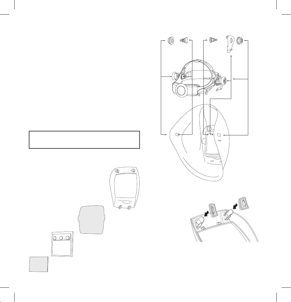
A A CC B
D
E
F
ZZ
WH70 BH3®HELMET AND HEADGEAR
ASSEMBLY
1. Insert screws (A) through the openings in the headgear (D).
2. Insert the headgear (D) into the helmet shell (F) as shown
in figure 1 and push the screws (A) through the rectangular
openings in the helmet shell.
3. Put the tilt adjustment (B) on the right side between the
screw (A) and helmet shell (F). Make sure that a small
pin is fixed in one of the three holes in the helmet shell.
Choose the right hole for your maximum comfort.
4. Tighten the nuts (C) on the screws (A). Before adequately
tightening them, place the headgear at the most comfort-
able distance from the filter opening by adjusting the
possition of headgear within the two rectangular holes in
the helmet shell.
5. The headgear size (D) can be adjusted by turning the rear
wheel (E) in order to fit any head size. Press the wheel
and hold it while turning, release the wheel when reaching
the position of maximum comfort, so that it will lock in the
required position.
The headgear is equipped with a replace-
able sweatband. Sweatbands are available
through your local dealer.
WASHERS ASSEMBLY
In order to assure adequate sealing in the hood and meeting the
safety standards, the WH70 BH3
®
must be additionally equiped
with a pair of washers. The washers are (Z) attached into the
two upper inner pins of the external control frame.
This manual suits for next models
3
Table of contents
Languages:
Other Surewerx Welding Accessories manuals


