Date: November 2016
Issue No: 2
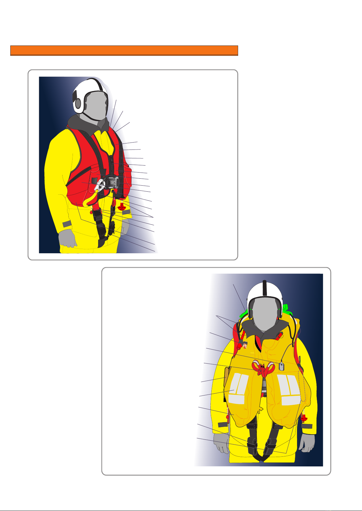
Crewsaver - Servicing Manual : Offshore 290 Lifejacket
Page
of 35
8
2.1.1 Service stations shall comply with the following as a minimum;
2.1.1.1 Servicing of Inflatable Lifejackets shall be carried out in a fully enclosed area only.
2.1.1.2 The area shall be well lit and protected from direct sunlight
2.1.1.3 The temperature and humidity shall be sufficiently controlled to ensure that the servicing of inflatable
Lifejackets may be carried out successfully.
2.1.1.4 The area shall be efficiently ventilated but free from draught
2.1.1.5 Sufficient tools (including specialist tools) shall be available to ensure Lifejackets may be
disassembled, tested and reassembled in accordance with this Manual. These shall include but not
limited to:
2.1.1.5.1 Manometers and pressure gauges
2.1.1.5.2 Oil free and dry air supply
2.1.1.5.3 Scales for weighing Gas Cylinders
2.1.1.5.4 Crewsaver Service tool kit (See 2.6). This is recommended but similar calibrated devices
may also be used.
2.1.1.6 Stock of materials and components to allow efficient servicing with readily available replacement parts
to ensure a prompt service for the customer.
2.1.1.7 Only personnel trained and certified in accordance with Crewsaver requirements are approved to
carry out Servicing and Maintenance. They must be holders of a valid Certificate issued by
Crewsaver.
2.1.1.8 The service station shall be of an approved standard.
2.1.1.9 Procedures shall be introduced to ensure that service bulletins, Manuals and replacement parts are
obtained from Crewsaver.
2.1.1.10 Subsequent to initial approval and thereafter the service station shall be subject to regular surveillance
by Crewsaver.
2.1.1.11 The service station must comply and have met all QA criteria in the Crewsaver servicing protocol file.
2.2.1 On receipt of the Lifejacket(s), check the state of the packaging before opening and notify the owner
and the company delivering the package of any defects or damage.
2.2.2 On opening the package, check the contents for their general condition and quantity.
2.2.3 Prepare Servicing Record Sheet.
2.2.4 Visually inspect the cover and inflation chamber for damage, abrasion, contamination etc. in
accordance with this manual.
2.2.5 Note replacements required on the record sheet.
2.2.6 Unless obvious damage is evident, test the Lifejacket in accordance with Section 6. If it is considered
that the damage found would cause the Lifejacket to fail the tests then corrective action shall be carried
out prior to testing.
2.2.7 Damaged areas shall be marked using wax based crayon only. Marks shall be made with a small circle
or
cross. Ballpoint, rollerball or other forms of ink shall not be used. If in doubt refer to Crewsaver for
guidance.
2.2.8 Repairs to the outer cover and the webbing are not permitted.
2.2.9 Repairs to welded components including the inflation chamber are expressly forbidden.
2.1 Service Stations
2.2 On Receipt Inspection
2
Section