Suspa MOVOTEC User manual

MOVOTEC
®
Q-Drive “Bolt-On”
Lift System Manual
by
Copyright © 2016 by
Suspa
®
Incorporated
All rights reserved. No part of this manual may be reproduced or transmitted
in any form or by any means, electronic or mechanical, including photocopying,
recording, or by any information storage and retrieval system
without permission in writing from Suspa
®
Incorporated.

05/26/16
670- 00018B
1
1.0 Table of Contents
2.0 Introduction........................................................................................................................2
3.0 Safety Instructions.............................................................................................................2
4.0 How it Works .....................................................................................................................5
4.1 Extension Cycle................................................................................................................5
4.2 Retraction Cycle:..............................................................................................................6
5.0 Unpacking Instructions.....................................................................................................6
6.0 Lift System Specifications.................................................................................................8
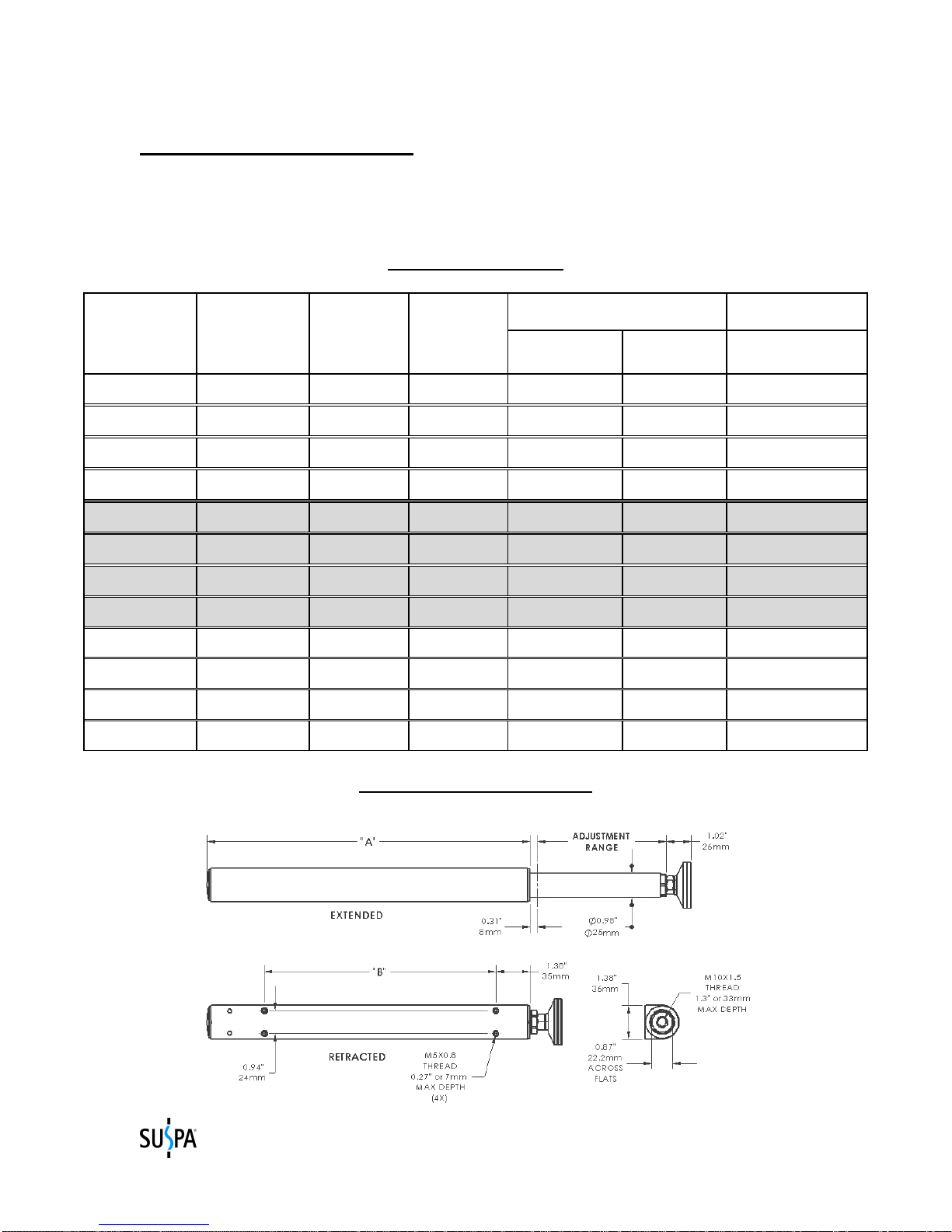
6.1 Lift Cylinder Specifications.............................................................................................8
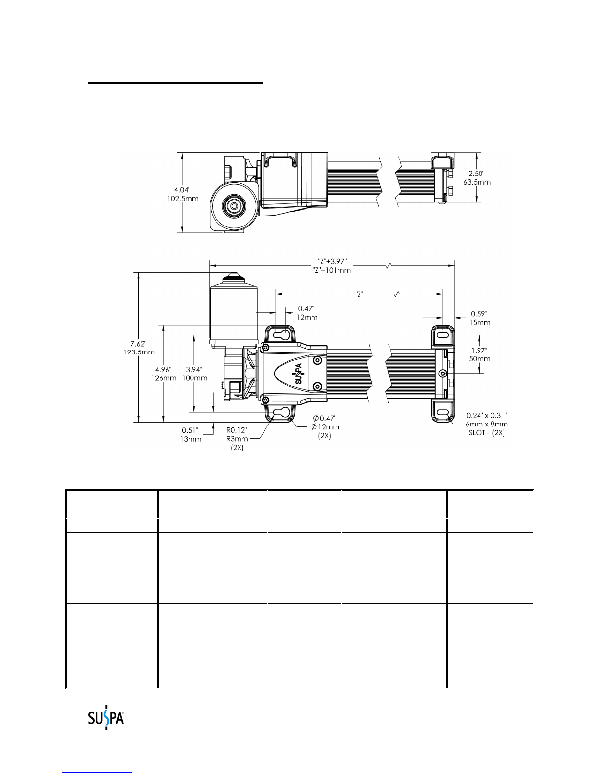
6.2 Motorized Pump Specifications.......................................................................................9
6.3 Motor Controller Specifications.....................................................................................10
6.4 Surface Mount Switch Specifications ............................................................................11
6.5 Regulatory Information..................................................................................................11
7.0 Installation Instructions..................................................................................................12
7.1 System Component Placement.......................................................................................12
7.2 Motorized Pump Installation..........................................................................................13
7.3 Motor Controller Installation .........................................................................................14
7.4 Low Profile Switch Installation......................................................................................15
7.5 Controller Cable Connections........................................................................................16
7.6 Lift Cylinder Installation................................................................................................17
7.7 Hydraulic Tubing and Cable Management ....................................................................20
7.8 Workstation Leveling.....................................................................................................20
8.0 Operation Instructions....................................................................................................22
8.1 Before Connecting to Power ..........................................................................................22
8.2 Connecting to Power......................................................................................................23
8.3 First Operation................................................................................................................23
8.4 System Extension Cycle.................................................................................................25
8.5 System Retraction Cycle................................................................................................25
8.6 Duty Cycle Monitoring ..................................................................................................26
8.7 Deceleration Zone..........................................................................................................26
8.8 System Reset Procedure.................................................................................................26
8.9 Limit Alteration Instructions..........................................................................................27
9.0 Troubleshooting...............................................................................................................28
10.0 Inspection and Maintenance.........................................................................................29
10.1 Changing Load Conditions...........................................................................................29
10.2 Motor and Load Alignment..........................................................................................29
10.3 Contamination..............................................................................................................29
10.4 Power Cord and Hydraulic Tubing Damage................................................................29
11.0 Warranty........................................................................................................................30
12.0 Replacement Parts.........................................................................................................31
13.0 Optional Accessories and Enhanced Capabilities.......................................................31
14.0 Disposal...........................................................................................................................31
15.0 Contact Information......................................................................................................31

05/26/16
670- 00018B
2
2.0 Introduction
For more than 30 years, Movotec® lift systems have been used to make work-surfaces
height adjustable. They have been used on industrial workbenches, small machine bases,
massage tables, physical therapy tables, packaging equipment, and many other
applications.
Years of experience, engineering, and research have resulted in a product that is proven,
time-tested and will deliver unparalleled performance.
Thank you for purchasing the Movotec® Crank Driven “Bolt-On” Lift System.
3.0 Safety Instructions
READ THE INSTRUCTIONS IN THIS MANUAL BEFORE ATTEMPTING TO
INSTALL, OPERATE, OR SERVICE THIS PRODUCT. FOLLOW THESE
SAFETY INSTRUCTIONS AT ALL TIMES.
This manual contains safety, installation, operation, maintenance, and user service
instructions for the Movotec
®
Q-Drive “Bolt-On” Lift System. Suspa
®
Incorporated is
not responsible for any alteration, misuse, misapplication, or abuse of this product
resulting in property damage, personal injury or death.
FAILURE TO FOLLOW THE INSTRUCTIONS IN THIS
MANUAL COULD RESULT IN FIRE, PROPERTY
DAMAGE, ELECTRIC SHOCK, PERSONAL INJURY
OR DEATH.
If you have any questions about the use of this product, the safety practices outlined in
this manual or would like a digital copy of this manual, please contact us (see Section 15
for contact information).
VERIFY SYSTEM SELECTION. Before the installing or operating the system,
please review the application to confirm that the correct Movotec
®
Lift System has been
selected. Pay particular attention to the load capacity and adjustment range ratings listed
on the blue product label.
HANDLE COMPONENTS WITH CARE. Do not handle system by the motor cables,
power cords or hydraulic tubing. Keep motor cables, power cords, and hydraulic tubing
far from heat, sharp edges and moisture. If motor cables, power cords, or hydraulic
tubing are damaged, discontinue use and have the suspect component replaced
immediately. Do not ever attempt to repair a damaged motor cable, power cord or
hydraulic tubing line.

05/26/16
670- 00018B
3
VISUALLY INSPECT COMPONENTS. Before installing and operating the system,
inspect all components for any damage that may have occurred during shipping and
installation. Do not attempt to disassemble system or system components for any reason.
If a defective component is found, contact Suspa
®
Incorporated for repair or replacement.
USE OF TRAINED AND QUALIFIED PERSONNEL System installation, operation,
and repair should only be done by persons having sufficient knowledge of the lift system
and the contents of this manual. In addition, they must have an understanding of all
warnings and precautionary measures noted in these safety instructions. Furthermore,
these individuals must be trained, instructed and qualified to switch electrical circuits and
equipment on and off in accordance with applicable technical safety regulations.
AVOID HAZARDOUS ENVIRONMENT. Do not operate the system outside. Do not
expose the system to damp or wet conditions. Avoid any chemical or corrosive
environments. Do not operate the system in the presence of flammable solvents,
propellants and/or explosive materials (i.e. gas, vapor, dust, etc.) Avoid temperatures
outside of the system rated operating temperature range 41°to 113°F (5° to 45°C). Do
not subject lift system components to vibration and/or impact load conditions.
INSTALLATION SAFEGUARDS. Do not use the system for any purpose other than
its intended function. Before operating system, make sure that the workstation has a
minimum clearance of 2 in. (51mm) from any other object or structure to prevent
pinching or crushing hazards. Do not allow wall, cabinet, electrical lines, hydraulic or
pneumatic lines, or any other fixed structures to obstruct the movement of the
workstation during operation.
KEEP CHILDREN AWAY. It is not recommended that children operate this
electrically powered lift device. If this device is used by or near children, close
supervision is absolutely necessary.
OBSERVE DUTY CYCLE. The term duty cycle refers to the amount of time that a
motor or system is in motion versus the amount of time that it is resting. The Movotec
®
Q-Drive “Bolt-On” Lift System is not designed to operate continuously without rest. It is
designed for intermittent use only and is rated for a 10% duty cycle. This means that if
the lift system is in motion for 1 minute, it must be at rest for at least 9 minutes before the
next operation. It is also important to note that the maximum system on-time is 1 minute.
To avoid damaging the system, the duty cycle must not be exceeded. Motor surfaces
can become warm after extended operation that exceeds the duty cycle. Provide adequate
ventilation to allow heat dissipation from within and around lift system components.
USE OF ACCESSORIES. Use caution when routing extension cords. Do not allow
cords to become pinched or stretched. Avoid positioning cords where they can become a
trip hazard. Use only spare parts and accessories authorized or supplied by Suspa
®
Incorporated. Do not replace or replenish lift system hydraulic fluid unless the fluid is
supplied by Suspa
®
Incorporated
.

05/26/16
670- 00018B
4
DO NOT INSERT OBJECTS. To reduce the risk of fire or electrical shock, do not
insert any objects into the system when powered.
MAINTENANCE SAFEGUARDS. Prior to performing any maintenance or service on
the device, remove the load from all lift cylinders and unplug the motor controller from
power source. The workstation or structure that the lift system is attached to should be
stabilized to prevent personal injury or property damage during maintenance or service
procedures.
RETRACT SYSTEM BEFORE MOVING. To reduce the risk of property damage and
personal injury, always retract the lift system fully before moving the equipment.
UNPLUG BEFORE CLEANING. Retract the lift system, unplug the motor controller
from power source and allow the system to cool before cleaning components. Clean
system components with a mild soap and water-damped cloth. Do not use corrosive
cleaning agents or high pressure wash systems to clean lift system components. Make
sure system is clean and dry before plugging into power source and operating the system.
SAVE THIS MANUAL FOR FUTURE REFERENCE.

05/26/16
670- 00018B
5
4.0 How it Works
Movotec
®
Q-Drive “Bolt-On” Lift Systems are comprised of three major component
subsystems; the motor drive, the pump and the lift cylinders. This section will explain
how each subsystem works together to make the lift system extend and retract.
Movotec
®
Q-Drive Schematic
4.1 Extension Cycle
The motor drive consists of a motor controller, a 24 VDC gear motor, and motor switch.
The motor controller converts AC line voltage to DC voltage to operate the 24 VDC gear
motor. It also controls motor speed and is programmed to operate within specific pump
upper and lower limits. The motor switch is used to activate the 24VDC gear motor for
lift system extension and retraction.
When the motor switch “UP” arrow button is depressed, the 24 VDC gear motor shaft
begins to rotate in a (CCW) counter-clockwise direction. Since the gear motor drive
shaft is mechanically coupled to the pump leadscrew shaft, the leadscrew shaft rotates in
the same (CCW) direction. As the gear motor continues to rotate in a (CCW) direction,
the threaded pusherblock moves up the leadscrew in the direction of arrow “A”. This
action drives fluid from the pressure elements, through the hydraulic tubing and into the

05/26/16
670- 00018B
6
lift cylinders causing them to extend. The gear motor will automatically shut off once the
programmed pump upper limit is reached.
4.2 Retraction Cycle:
(Refer to Movotec
®
Q-Drive Schematic on page 7)
When the motor switch “DN” arrow button is depressed, the 24VDC gear motor shaft
begins to rotate in a (CW) clockwise direction. Since the gear motor shaft is
mechanically coupled to the pump leadscrew shaft, the leadscrew shaft rotates in the
same (CW) direction. As the gear motor continues to rotate in a (CW) direction, the
threaded pusherblock moves down the leadscrew in the direction of arrow “B”. As long
as there is sufficient load on the lift cylinder piston rods, the fluid in the lift cylinders
flows back through the hydraulic tubing and into the pressure elements. The gear motor
will automatically shut off once the programmed pump lower limit is reached.
5.0 Unpacking Instructions
The system comes packaged in a cardboard carton. To unpack the system:
•Check the carton label to confirm that you have received the correct system; open
the carton and remove packaging material.
•Carefully remove the system from the carton. Verify all components are present
(reference chart below) and that the correct lift system was received.
Do not handle the lift cylinders and motorized pump by the hydraulic tubing. Incorrect
handling of hydraulic tubing could weaken the tubing material and system tubing
connections.
DAMAGE TO TUBING OR TUBING CONNECTIONS
COULD CAUSE FLUID LOSS AND UNCONTROLLED
DESCENT OF THE WORK-SURFACE.

05/26/16
670- 00018B
7
•Verify that all of the listed components are present; carton should contain:
System Component Quantity
(A) Pump 1
(B) Gear Motor (attached to pump) 1
(C) Motor Controller 1
(D) Lift Cylinders (connected to pump)
4
(E) Low Profile Switch 1
(F) Drill Templates 4
(G) Cable Ties 8
(H) Mounting Clips 8
(I) Power Cord 1
(J) Motor Cable
1
•If the lift system is damaged or any component is missing, please contact Suspa
®
Incorporated to resolve the issue before installing the system.
•Dispose of the all packaging materials in an ecologically sound manner; if
uncertainty exists with regards to disposal / recycling details, please contact
Suspa
®
Incorporated

05/26/16
670- 00018B
8
6.0 Lift System Specifications
The “A”, “B”, and “Z” dimensions shown in the table and drawings below vary
depending on the system lift capacity and the adjustment range of the selected system.
System Part Numbers
120V
Lift System 230V
Lift System Adjustment System Lift CB "Bolt-On" Cylinder Motorized Pump
Part Part Range Capacity "A" "B" "Z"
Number Number (mm/in) (kg/lbs) (mm/in) (mm/in) (mm/in)
MLS-00001E MLS-00009E 150/5.9 340/750 258.5/10.18 165/6.50 330/12.99
MLS-00002E MLS-00010E 200/7.9 340/750 333.5/13.13 240/9.45 390/15.35
MLS-00003E MLS-00011E 300/11.8 340/750 463.5/18.25 340/13.39 510/20.08
MLS-00004E MLS-00012E 400/15.7 340/750 558.5/21.99 340/13.39 632/24.88
MLS-00005E MLS-00013E 150/5.9 454/1000 258.5/10.18 165/6.50 390/15.35
MLS-00006E MLS-00014E 200/7.9 454/1000 333.5/13.13 240/9.45 450/17.72
MLS-00007E MLS-00015E 300/11.8 454/1000 463.5/18.25 340/13.39 632/24.88
MLS-00008E MLS-00016E 400/15.7 454/1000 558.5/21.99 340/13.39 760/29.92
MLS-00080E MLS-00084E 150/5.9 590/1300 258.5/10.18 165/6.50 450/17.72
MLS-00081E MLS-00085E 230/9.1 590/1300 463.5/18.25 340/13.39 632/24.88
MLS-00082E MLS-00086E 300/11.8 590/1300 463.5/18.25 340/13.39 760/29.92
MLS-00083E MLS-00087E 393/15.7 590/1300 558.5/21.99 340/13.39 936/36.85
6.1 Lift Cylinder Specifications
CB4xx cylinders are rated for a maximum load of 250lb (113.4kg) each.

05/26/16
670- 00018B
9
6.2 Motorized Pump Specifications (Refer to chart below for “Z” dimensions)
The Movotec
®
Q-Drive gear motor used with the motorized pump shown below is rated for
24 volts DC. The no-load speed of the gear motor is 160 rpm. The no-load current is 3A.
The maximum rated operating torque is 75 lb-in (8.5N-m).
Pump “Z” Dimension
PUMP
DESCRIPTION
“Z” DIMENSION
(mm) OVERALL
“Z” (mm) “Z” DIMENSION
(inch) OVERALL
“Z” (inch)
Qx809 330 431 12.99 16.96
Qx812 390 491 15.35 19.32
Qx818 510 611 20.08 24.05
Qx824 632 733 24.88 28.85
Qx830 760 861 29.92 33.89
Qx839 936 1037 36.85 40.82
Qx612 390 491 15.35 19.32
Qx615 450 551 17.72 21.69
Qx623 632 733 24.88 28.85
Qx625 650 751 25.59 29.56
Qx631 760 861 29.92 33.89
Qx639 936 1037 36.85 40.82

05/26/16
670- 00018B
10
6.3 Motor Controller Specifications
Motor Controller Parameter Specification
Supply Voltage / Frequency 120V / 50-60Hz (US)
230V / 50-60HZ (Europe)
Standby Power Consumption <0.6W
Switch Operating Voltage / Current 5VDC / 150mA
Hall Sensor Operating Voltage / Current 5VDC / 150mA
Operating Temperature Range 32º to 86ºF (0º to 30ºC)
Operating Humidity Range 5% to 85% (non-condensing)
Storage Temperature Range -40º to 185ºF (-40º to 85ºC)
Storage Humidity Range 5% to 90% (non-condensing)
Protection Class I
Motor Controller Dimensions 10.4in x 4.1in x 1.5in
(264mm x 103mm x 37mm)
Weight 1.1 lb (0.5kg)
Each controller comes complete with power cable, 3m (9.8ft.) in length.
US-based systems use a 3-prong, NEMA 5-15P type plug. European-based systems use a
“Schuko” style, CEE 7/7 type plug.

05/26/16
670- 00018B
11
6.4 Low Profile Switch Specifications
The operating voltage and current of the low profile switch when attached to the motor
controller is 5VDC and 150mA, respectively.
6.5 Regulatory Information
UL Component Recognition
The Movotec
®
Q-Drive gear motor, 120V motor controller, and motor cable have passed
relevant UL safety testing under UL962, the standard for Household and Commercial
Furnishings. As a group, these three components are considered to be a UL Recognized
Component and have been labeled with the UL Component Recognition mark for the
United States and Canada shown below (Reference: UL File #258745).
RoHS Directive (2002/95/EC)
Suspa
®
Incorporated has examined all of the materials and processes utilized in the
production of Movotec
®
Q-Drive “Bolt-On” Lift Systems and determined that this
product is in compliance with European Union RoHS Directive (2002/95/EC).
CE Information
All known, relevant EU guidelines were observed and applied in the design and
manufacture of this product. For detailed information on the relevance of CE to
Movotec
®
, please contact Suspa
®
Incorporated.

05/26/16
670- 00018B
12
7.0 Installation Instructions
FOLLOW ALL SAFETY INSTRUCTIONS CONTAINED
IN SECTION 3.0 OF THIS MANUAL BEFORE
INSTALLING THIS PRODUCT. FAILURE TO
FOLLOW THE INSTRUCTIONS IN THIS MANUAL
COULD RESULT IN FIRE, PROPERTY DAMAGE,
ELECTRIC SHOCK, PERSONAL INJURY OR DEATH.
7.1 System Component Placement
There are many system components in a Movotec
®
Q-Drive “Bolt-On” Lift System.
Since all of these components are physically linked together with hydraulic tubing and
electrical cables, it is very important to make sure that the components are located on the
workstation so that everything can be connected safely and correctly.
7.1.1 Motorized Pump Placement - The motorized pump can be mounted in any
orientation, however it is recommended to mount the unit horizontally. The
motorized pump should be mounted so that there is enough hydraulic tubing to
reach each lift cylinder and enough clearance for the minimum hydraulic tubing
bend radius of 2 in. (51mm) to be maintained. Suspa
®
Incorporated offers a black
thermoformed plastic motor cover to further protect the gear motor and cable
connections from possible damage. The motor cover can be purchased on our
website at https://shop.suspa.com/storefront.aspx.
7.1.2 Motor Controller Placement - There should be enough power cord length
to facilitate movement of the workstation without the power cord connector
becoming separated from the motor controller during operation. To accomplish
this and to ensure that there is enough power cord length to reach a power
receptacle, the motor controller should be placed toward the center and backside
of the workstation. In addition, the motor controller should be placed so that it is
in relatively close proximity to the gear motor. If this is not possible, Suspa
®
Incorporated offers motor extension cables to make up the difference. These
cables can be purchased on our website at https://shop.suspa.com/storefront.aspx.
7.1.3 Switch Placement - The switch should be mounted on the side of the
workstation where it is most accessible to the user and so that there is enough
switch cable to reach the motor controller. Alternate motor switches can be
purchased on our website at https://shop.suspa.com/storefront.aspx.
7.1.4 Lift Cylinder Placement – The lift cylinders should be located on the
workstation so that the load on the system is balanced. Lift cylinders must also be
oriented vertically and parallel to one another to prevent cylinder binding during
extension and retraction cycles. Suspa
®
Incorporated offers an assortment of
brackets to reduce the number of holes to be drilled for lift cylinder mounting and

05/26/16
670- 00018B
13
to facilitate system installation. These cylinder mounting brackets can be
purchased on our website at https://shop.suspa.com/storefront.aspx.
7.1.5 Tubing and Cable Placement – Hydraulic tubing and power cables must
be kept away from sharp edges and moving parts. Contact with moisture and heat
must also be avoided. Hydraulic tubing and power cables should fixed to the
workstation or structure using the cable ties and mounting clips provided.
Additional cable ties and mounting clips can be purchased on our website at
https://shop.suspa.com/storefront.aspx.
7.2 Motorized Pump Installation
•If possible, orient workstation as shown for ease of component placement and
installation.
•Place motorized pump in the desired location. Ensure enough room exists for the
motor controller.
•Mark and prepare four holes in the locations provided by the motor bracket and
rear pump support bracket.

05/26/16
670- 00018B
14
•Mount the motorized pump assembly to the surface. Please note that mounting
screws are not provided with system. To avoid deforming the plastic housing, it
is recommended to use metallic washers when installing the motor bracket
fasteners.
•Check mounting screws to ensure that the unit is tightly secured.
7.3 Motor Controller Installation
•Place the motor controller in the desired location, ensuring that the motor cable is
long enough to reach the motor ports after installation is complete.
•Mark and prepare two mounting holes for the control box

05/26/16
670- 00018B
15
•Install controller using mounting screws and check to ensure that the unit is
secured.
7.4 Low Profile Switch Installation
•Place the switch in the desired location on the underside of the work surface.
•Align the switch body with front edge of the work-surface. Mark and prepare two
holes in the locations provided in the switch enclosure.
•Using the appropriate screws, mount the switch to the work-surface taking special
care not to over tighten the screws. While (2) mounting screws are included with
the switch, ensure they will work for the particular application before using to
mount switch.
•Check mounting screws to ensure that the switch is secured.

05/26/16
670- 00018B
16
7.5 Controller Cable Connections
•The motor controller ports are labeled on the top side of the control box.
•The switch plug is blue and corresponds with the round switch port shown
above. The motor cable plugs are marked “M1” and “M2” on the cable, and
correspond with the (M1) and (M2) motor ports shown above (white, rectangular
plugs).
•The switch plug has an arrow to indicate proper connection alignment. This
arrow must face away from the work-surface and toward their corresponding
connection port.
To make the controller connections:
•Connect the black motor cable plugs in to their respective (M1) and (M2) motor
ports. Firmly press the plug into the port until the plastic hook “clicks” in place.

05/26/16
670- 00018B
17
It is important to install both motor cables in to the control
box, or the system will not operate! Ensure both
connections are secure and in the correct ports on the
controller.
•Connect the blue switch cable plug to the (HS) switch port. Firmly press the plug
into the port to ensure that a complete connection has been made.
•Connect power cord to motor controller IEC power port. Firmly press power cord
plug into the IEC receptacle to ensure that a complete connection has been made.
•Check all connections to ensure that they have been made correctly and
completely.
7.6 Lift Cylinder Installation
•Unwrap lift cylinders and drilling templates from bubble wrapping. Dispose of
bubble wrapping material in an ecologically sound manner.
NOTICE

05/26/16
670- 00018B
18
•Thoroughly clean all workstation leg mounting surfaces to ensure the cylinder
drilling templates will adhere. Apply the drilling templates parallel to the
workstation leg surfaces, making sure that the templates are oriented correctly.
Please note that the drilling templates are shown upside down due to the
orientation of the workstation.
Lift cylinder mounting hole locations vary depending
upon the lift cylinder model number. The lift cylinder
model number can be found on the product label.
“Bolt-On” lift cylinder model numbers begin with “CB”
(i.e. CB415).
Lift cylinder mounting instructions can also be found
printed on the drilling templates provided with the system.
•Drill (4) - 6mm holes in the appropriate locations indicated on each drill
templates.
•Select cylinder mounting screws with a property class of 8.8 or greater.
NOTICE

05/26/16
670- 00018B
19
To avoid lift cylinder damage, the screw depth must not
exceed 7mm (0.27 in.) into the lift cylinder housing as
shown below.
•Install each cylinder to the workstation frame using (4) - M5 screws of the
appropriate length. Suspa
®
Incorporated recommends a lift cylinder mounting
screw thread engagement of 0.196-0.275in. (5-7mm).
•Make sure there is enough flexible hydraulic tubing to reach each workstation leg
without putting any tension on the tubing and while maintaining the minimum
flexible tubing bend radius of 2in. (51mm). Each standard system is shipped with
hydraulic tubing cut-to-length and assembled to the unit, (2) lengths at 8.2 ft.
(2.5m), and (2) lengths at 10.2 ft. (3.1m). Custom lengths of tubing can also be
ordered.
•Check the lift cylinder mounting screws to ensure that they are tightly secured to
the workstation. Take special care not to over tighten lift cylinder mounting
screws. Suspa
®
Incorporated recommends a lift cylinder mounting screw
tightening torque of 4.0-4.5 N-m (35-40 lb-in).
NOTICE
Other manuals for MOVOTEC
3
Table of contents
Other Suspa Lifting System manuals
Popular Lifting System manuals by other brands

HiGH-LiFT
HiGH-LiFT YL-9FW Installation & operation manual

Maxon
Maxon Tuk-A-Way GPT Series installation manual

Maxon
Maxon MXT-25 installation manual

Century
Century EB-4 owner's manual

morse
morse 195A-A Operator's manual

Challenger Lifts
Challenger Lifts EW1020-QC Installation, operation & maintenance manual