SUTO S132 Manual

English
Instruction and Operation Manual
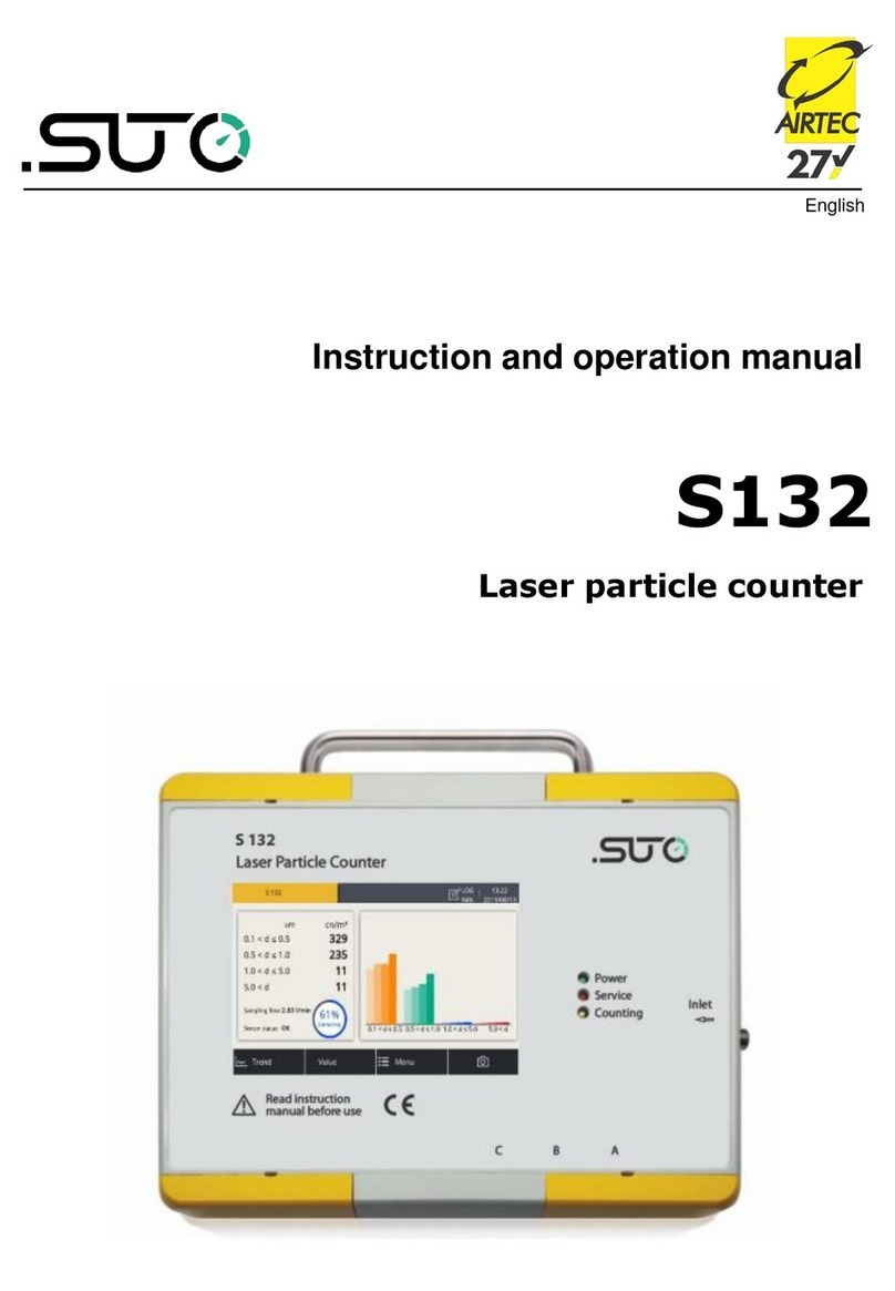
S132
Laser Particle Counter

Dear Customer,
Thank you for choosing our product.
Before you start up the device please read this manual in full and
carefully observe instructions stated in this manual. The manufacturer
cannot be held liable for any damage that occurs as a result of non-
observance or non-compliance with this manual.
Should the device be tampered with in any manner other than a
procedure that is described and specified in the manual, the warranty is
void and the manufacturer is e empt from liability.
The device is destined e clusively for the described application.
SUTO offers no guarantee for the suitability for any other purpose.
SUTO is also not liable for consequential damage resulting from the
delivery, capability or use of this device.
2 S132

Table of Contents
1 Safety instructions......................................................................4
2 Registered trademarks.................................................................6
3 Application.................................................................................7
4 Features....................................................................................7
5 Technical data.............................................................................8
5.1 General data.........................................................................8
5.2 Electrical data.......................................................................8
5.3 Output signals......................................................................9
5.4 Counting efficiency................................................................9
5.5 Procedure of general particle counting .....................................9
6 Dimensional drawing..................................................................10
7 Installation ..............................................................................11
7.1 Installation methods............................................................11
7.2 Installation procedure .........................................................13
7.3 Electrical connection............................................................15
8 Configuration ...........................................................................17
8.1 Integrated display...............................................................17
8.2 Service kit..........................................................................17
8.3 E ternal display ..................................................................17
9 Operation using the integrated display.........................................18
9.1 Value view..........................................................................18
9.2 Icons in the status bar.........................................................19
9.3 Trend view..........................................................................20
9.4 Menu.................................................................................21
9.5 Sensor settings...................................................................22
9.5.1 Analog output...............................................................22
9.5.2 Counter setting.............................................................23
9.5.3 Alarm settings...............................................................24
9.5.4 Modbus settings............................................................25
9.5.5 Sensor Info...................................................................25
10 LED indicators at the front panel................................................26
11 Signal outputs.........................................................................27
11.1 Analog output ..................................................................27
11.2 Modbus InterfaceDigital output............................................27
11.3 Alarm output ....................................................................29
12 Optional accessories................................................................30
13 Calibration..............................................................................31
14 Maintenance...........................................................................31
15 Disposal or waste....................................................................31
S132 3

1 Safety instructions
1 Safety instructions
Please check if this instruction manual matches the
product type.
Please observe all notes and instructions indicated in this
manual. This manual contains essential information that must
be observed before and during installation, operation and
maintenance. Therefore this manual must be read carefully by the
technician as well as by the responsible user or qualified personnel.
This instruction manual must be available at the operation site of the
product at any time. In case of any obscurities or questions regarding
this manual or the product, please contact the manufacturer.
WA NING!
Compressed air!
Any contact with quickly escaping air or bursting
parts of the compressed air system can lead to
serious injuries or even death!
•Do not e ceed the ma imum permitted pressure range (see
sensors label).
•Use only pressure-tight installation material.
•Prevent persons from being hit by escaping air or bursting parts of
the instrument.
•The system must be pressureless during maintenance work.
WA NING!
Voltage used for supply!
Any contact with energized parts of the device may
lead to an electrical shock which can lead to serious
injuries or even death!
•Consider all regulations for electrical installations.
•The system must be disconnected from any power supply during
maintenance.
•Any electrical work on system is allowed only by authorized
qualified personal.
4 S132

1 Safety instructions
ATTENTION!
Permitted operating parameters!
Observe the permitted operating parameters. Any
operation beyond these parameters can lead to
malfunctions and may lead to damage on the product
or the system.
•Do not e ceed the permitted operating parameters.
•Make sure that the product is operated under its permitted
conditions.
•Store and operate the product at the permitted temperature and
pressure.
•The product should be maintained and calibrated frequently, at
least annually.
General safety instructions
•It is not allowed to use the product in e plosive areas.
•Please observe the national regulations before and during
installation and operation.
emark
It is not allowed to disassemble the product.
ATTENTION!
Measurement values can be affected by malfunction!
The product must be installed properly and
maintained frequently. Otherwise it may lead to
wrong measurement values, which can lead to
wrong results.
Storage and transportation
•Make sure that the transportation temperature for the product
without display is between -30 ... +70°C and for the product with
display between -10 ... +60°C.
•It is recommended to use the packaging that comes with the
product for storage and transportation.
•Make sure that the storage temperature of the product is between
-10 ... +50°C.
S132 5

1 Safety instructions
•Avoid direct UV and solar radiation during storage.
•The storage humidity must be < 90% with no condensation.
ATTENTION!
Equipment may get damaged!
Please make sure, that your measuring point is free
of excessive contamination and dirt. This should
maintained before every measurement.
•Observe the measuring point always before measurement if it is
free of contamination like water drops, oil drops or other rough
contamination.
•Should water hit the inner electronics, the senors could be
seriously damaged.
•Before you start to measure, check your measurement point by
using a simple filter to see if any rough contamination is present.
(E ample of such a test device is shown below. Ask the supplier if
not sure.)
2 egistered trademarks
SUTO®Registered trademark of SUTO iTEC
MODBUS®Registered trademark of the Modbus Organization,
Hopkinton, USA
Android™,
Google Play
Trademarks of Google LLC
6 S132

3 Application
3 Application
The S132 is a laser particle counter, which is designed to measure
particles in compressed air or compressed gases. For the permissible
operating parameters, see chapter 5 Technical data.
The measurement result can be the number of particles per ft3 or m3.
You can choose the unit setting, as needed, using the optional
integrated display, an e ternal display, or the service kit.
The S132 laser particle counter is mainly used in compressed air
systems in industrial environments, and is not designed for use in
e plosive areas. To use it in e plosive areas, please contact the
manufacturer.
4 Features
•Measures particle content in compressed air or compressed gases.
•Easy connection through sampling hose and quick connector.
•Applicable to stationary or portable applications.
•Measures particles larger than 0.1 µm.
•Compliance with ISO 8573-4.
•Service indication through LED.
•Connectable to display and data logger produced by the
manufacturer and by third-party manufacturers.
•IP65 casing provides robust protection in rough industrial
environments.
•Optional integrated display for monitoring and configuration.
S132 7

5 Technical data
5 Technical data
5.1 General data
Parameters Particle counts per ft3 or m3
Principle of
measurement
Laser detection
Sensor LED-laser
Measured medium Compressed air
Measuring channels CH1: 0.1 < d ≤ 0.5 μm
CH2: 0.5 < d ≤ 1.0 μm
CH3: 1.0 < d ≤ 5.0 μm
CH4: 5.0 μm < d (configurable)
Flow rate 2.83 l/min
Sample rate 1 minute sampling time (Values are updated
every one minute.)
Ambient temperature +10 ... +40°C
Humidity of the
measured medium
< 90% rH, no condensation
Operating pressure 0.3 ... 1.5 MPa
Housing material PC, Al alloy
Protection class IP65
Dimensions See the dimensional drawing on page 10.
Display & data logger
(optional)
5” touch screen, 800 480 pi els
100 million values
Weight 3.2 kg
5.2 Electrical data
Power supply 24 VDC, 10 W without display
24 VDC, 20 W with display
8 S132

5 Technical data
5.3 Output signals
Analogue output 4 ... 20 mA
Digital output RS-485, Modbus/RTU
Alarm output NO, 40 VDC, 0.2 A
5.4 Counting efficiency
Counting efficiency
per ISO 21501-4
30 ... 70% of d > 0.1 µm
90 ... 110% of d ≥ 0.3 µm
5.5 Procedure of general particle counting
1. The S132 does not count any particles in the first 5 minutes.
During this period, it performs a purge process to ensure that any
remaining particles in the system are blown out.
2. After purging, the S132 starts sampling at a sampling interval of 1
minute.
a. In the ne t 40 minutes, S132 classifies the sampled values
based on particle sizes and then accumulates them.
b. After the 40 minutes, every one minute (sampling interval),
S132 removes the earliest sample values from the accumulated
values, and then add the latest sampled value into the
accumulated values to obtain the accumulated particle values
within the last 40 minutes.
S132 9
Other manuals for S132
1
Table of contents
Other SUTO Cash Counter manuals


