Sven BTR5-10 User manual

www.sven.ѵ
OPERATION
MANUAL
BTR5-10
5.1 Active Home Theater
Speaker System

Congratulations on your purchase of the Sven speaker system!
COPYRIGHT
© 2014. SVEN PTE. LTD. Version 1.0 (V 1.0).
This Manual and information contained in it are copyrighted. All rights reserved.
TRADEMARKS
All trademarks are the property of their legal holders.
NOTICE OF RESPONSIBILITY RESTRICTION
Despite the exerted eԚorts to make this Manual more exact, some discrepancies may occur. The
information in this Manual is given on «as is» terms. The author and the publisher do not bear any
liability to a person or an organization for loss or damage which has arisen from the information
contained in this Manual.
CONTENTS
1. BUYER RECOMMENDATIONS ..................................................
.............
2. PACKAGE CONTENTS.............................................................
............
3. SAFETY PRECAUTIONS ..................................................
...................
4. TECHNICAL DESCRIPTION ....................................................
................
5. PREPARATION AND OPERATION ..........................................
......................
6. TROUBLESHOOTING...............................................................
.................
7. TECHNICAL SPECIFICATIONS ....................................................
...........
1
2
2
2
5
10
11
1. BUYER RECOMMENDATIONS
•Unpack the device carefully. Make sure there are no accessories left in the box. Check up the
device for damage; if the product was damaged during transportation, address the ԛrm which
carried out the delivery; if the product functions incorrectly, address the dealer at once.
•Check up the package contents and availability of the warranty card. Make sure the warranty card
has a shop stamp, a legible signature or the seller’s stamp and purchase date, and the number of
the wall mount corresponds to that in the warranty card. Remember: in case of warranty card loss
or discrepancy of numbers you forfeit the right for warranty repairs.
• Do not switch on the speaker system immediately after you bring it into a room from environment
with negative temperature! After unpacking, the speaker system should be kept in conditions of
room temperature for at least 4 hours.
•Before installing and using the speaker system, read this Manual carefully and keep it for future
reference.
Technical support is on www.sven.Н
ENG
1
Operation Manual BTR5-10

2. PACKAGE CONTENTS
•Subwoofer – 1 pc
•Satellite speakers – 5 pcs
•Audio cable – 5 pcs
•2RCA to 2RCA signal cable – 3 pcs
•2RCA to 3.5 mm mini-jack adapter – 3 pcs
•Remote control – 1 pc
•CR2025 battery – 1 pc
•FM antenna – 1 pc
•AM antenna – 1 pc
•Operation manual – 1 pc
•Warranty card – 1 pc
3. SAFETY PRECAUTIONS
•To avoid electric shock, do not open the MSS and do not perform repairs by yourself. Service and
repairs should be performed only by qualiԛed specialists in an authorized service center. The list of
authorized service centers is available on www.sven.Н
•Do not allow the circuit of wires (including the grounded ones) between the speakers, on the
power ampliԛer or the ground, for it causes damage to the power ampliԛer output stage.
•Do not touch the MSS power cord plug pins for 2 seconds after unplugging it from the mains.
•Disconnect the MSS from the mains system during a fuse replacement. Use fuses of the same
type and rated value. Do not use hand-made fuses.
•Do not put foreign objects inside the holes of the MSS.
•Protect the MSS from high humidity, water and dust.
•Protect the MSS from heating: do not place it closer than 1 m from a heat source. Do not expose
it to direct sunlight.
•Do not place any open Ԝame sources on or close to MSS.
•Do not place the MSS in poorly ventilated areas. Leave an air gap of 10 cm or more. When
operating the MSS, do not put any devices on it, do not cover it with cloth or other objects pre-
venting it from cooling.
•Do not use any chemical agents for cleaning. Clean it with dry soft cloth only.
4. TECHNICAL DESCRIPTION
BTR5-10 5.1 Home Theater Speaker System (HTSS) equipped with AM/FM tuner is designed for
playing music and sounding games, movies, etc., as well as being used as radio tuner. The built-in
ampliԛer allows to connect the speaker system to virtually any audio source. Remote control is
included.
Caution! High voltage inside! To avoid the risk of electric
shock do not open or touch elements inside.
ENG
2
5.1 Active Home Theater
Speaker System

Special features
• Built-in 6-CH ampliԛer
• Built-in AM/FM tuner
• Analog 5.1 input, two stereo AV inputs for
connection to various audio devices
• Electronic audio input switch
• Full-function remote control
• Master volume and subwoofer volume
control
• Individual volume controls for front, rear
and center channel satellites
• LED display
• Magnetic shielding
• Wooden (MDF) cabinets of the subwoofer
and satellites
Subwoofer design
aDisplay screen
bVOLUME: master volume control knob
cSTANDBY: standby mode button
dINPUT: audio source selection button
e2.1/5.1: 2.1/5.1 mode switch button
fMUTE: MUTE button
gSUB+: subwoofer volume up
hSUB–: subwoofer volume down
iFM ANT: FM antenna terminal
jAM GND/AM ANT: AM antenna terminals
k2CH INPUT: audio source inputs
lDVD (5.1CH) INPUT: 5.1 audio source
input
mAUDIO OUTPUT: audio outputs for front,
rear and center channels
nPOWER: POWER ON/OFF switch
oPower cord
f
g
h
b
a
c
d
e
FR
FL
CEN
SR
SL
i
j
k
l
m
n
o
FRFL
SRSL
SWCEN
AUX
PC
DVD(5.1CH) INPUT 2CH INPUTAUDIO OUTPUT
CEN
Fig. 1. Subwoofer control panel
Fig. 2. Subwoofer rear panel
ENG
3
Operation Manual BTR5-10

i
h
g
f
e
c
b
j
l
m
o
p
q
r
s
t
k
d
a
STANDBY
VOL VOL
123
456
789
0
SCAN
TUNE
TUNE
MEMORY
BTR5-10
10
FM/AM
+
n
FRONT CEN SUB
SUBCEN
SURROUND
SURROUND
FRONT
BASS BASSTREBLE TREBLE
DVD PC AUX 2.1/5.1
RESET
Remote control
aSTANDBY: standby mode button
bPC: PC
signal source selection
cDVD: DVD (5.1CH)
signal source selection
dAUX: AUX
signal source selection
eSURROUND +/-:
rear channels volume control buttons
fFRONT+/-:
front channels volume control buttons
gTREBLE+/-: treble level control buttons
h0 – 9:
numeric keypad
i10+:
numeric keypad multiplier
jMUTE: sound oԚbutton
kRESET: return to default settings
l2.1/5.1: 2.1/5.1 mode switch button
mVOL+/-: master volume control buttons
nCEN+/-:
center channel volume control buttons
oSUB +/-:
subwoofer channel volume control buttons
pBASS+/-: bass level control buttons
qSCAN:
tuner auto scan
rTUNE+/-: tuner manual adjustment
sFM/AM: FM and AM band selection
tMEMORY: saving tuner settings
Remote control battery installation
• Open the battery compartment on the back of the
remote control.
• Insert the CR2025 battery (included).
• Close the battery compartment.
Notes:
• Use the remote control at an angle of no more
than 30°, no more than 7 meters away.
• Direct the remote control at the IR receiver
display on the subwoofer.
• If the remote control does not work, check the battery or replace the discharged battery
with a new one.
• Remove the battery from the remote control if you don’t intend to use it for a long time
(more than a week).
Fig. 3. Remote control
ENG
4
5.1 Active Home Theater
Speaker System

5. PREPARATION AND OPERATION
Speaker placement
• To achieve optimum sound, it’s recommended that you place the speakers according to Fig. 4.
The center and front speakers should be located along an imaginary circle with the distance
between the listener and the center channel speaker as a radius, and the listener’s head as the
center. Each of the three speakers should be placed at equal distance from the listener. The front
speakers and the listener make up an equilateral triangle. The rear speakers are placed at the same
distance from the listener (on the imaginary circle, too) at an angle of nearly 110° to the Listener –
Display axis.
• Avoid placing your speakers in the corners and close to walls, as this can lead to unwanted
resonance and distortions. If possible, place them at least 20 cm away from walls.
• For more accurate perception, the tweeters should be at the listener’s ear level.
• Do not locate the speakers in niches. Such placement can aԚect the sound badly, especially in
the lows.
• The subwoofer emits non-directional sound, therefore it can be located in any place of the room
where it sounds the best.
Fig. 4. Speaker placement
A
AA
A
A
A
30° 30°
110° ± 10° 110° ± 10°
Front right
speaker
Front left
speaker
Subwoofer
Rear left
speaker Rear right
speaker
Center
speaker
ENG
5
Operation Manual BTR5-10

Connecting the satellites to the subwoofer
• Before connecting, make sure that the device is unplugged. Join the connection cables as shown
in Fig. 5. Please note that the red (+) terminals of the satellites should be connected to the red
terminals of the subwoofer (+ о+), while the black (–) terminals of the satellites should be
connected to the black terminals of the subwoofer (– о–).
• Check for correctness of polarity connection and absence of contact between bared wires and
with metal parts of equipment.
Connecting an audio source
BTR5-10 5.1 Home Theater Speaker System can be connected to virtually any audio source (see
connection diagram, Fig. 6).
• Before connecting, make sure that the device is unplugged.
• To connect the speakers to a CD/DVD/VHS-player or TV, use the 2RCA to 2RCA stereo signal
cables. To connect the HTSS to a PC sound card or an ǀDŽ3/CD player, use the 2RCA to 2RCA sig-
nal cable together with the included 2RCA to 3.5 mm mini-jack adapter.
FR
FL
CEN
SR
SL
FRFL
SRSL
SWCEN
AUX
PC
DVD(5.1CH) INPUT 2CH INPUTAUDIO OUTPUT
CEN
Rear left satellite Rear right satellite
Centrer channel
satellite
Front left satellite Front right satellite
Subwoofer
rear panel
Fig. 5. Speakers connection diagram
ENG
6
5.1 Active Home Theater
Speaker System

FR
FL
CEN
SR
SL
FRFL
SRSL
SWCEN
AUX
PC
DVD(5.1CH) INPUT 2CH INPUTAUDIO OUTPUT
CEN
FL
SL
CESW
SR
FR
Fig. 6. Audio source connection diagram
Signal cables
2RCA to mini-jack
5.1-channel
sound card
Subwoofer
rear panel
• Be sure to connect the left and right channels correctly. The left RCA jacks should be inserted into
the left ports of the ampliԛer (usually white), and the right RCA jacks should be inserted into the right
ports of the ampliԛer (usually red).
Note. Accuracy and reliability of the cables’ connection directly affects the sound quality.
Check for absence of contact between the bared wires and with metal parts of the equip-
ment. AM antenna
FM antenna
CD player
DVD player
PC
2RCA to mini-
jack adapter
2RCA to 2RCA
signal cables
Power cord
ENG
7
Operation Manual BTR5-10

Fig. 7. ƵM antenna connection
Installation and Connection of Antennas
FM Antenna Connection
• Insert the included room FM antenna into the FM ANT terminal on the subwoofer rear panel, as
shown in Fig. 5. Install the FM antenna in such a way that reception quality is satisfactory, and then
ԛx the position of the antenna.
Note. In buildings with weak FM signal, use an external 75 Ohm FM antenna. Typically,
a three-element antenna is enough, but in areas with weak FM signal it is necessary to use
an FM antenna with 5 or more elements.
ƴM Antenna Connection
• To install the loop antenna (see the Fig. 7 below), ԛx the bracket to the hole at the bottom of the
antenna (step 1).
• Turn the visor of the AM terminal counterclockwise to loosen it slightly, insert the cord of the loop
antenna under the visor and turn the visor clockwise to ԛrmly clamp the cord (step 2). Gently pull
the cord to make sure it is securely ԛxed. Install the antenna in a niche or hang it on the window
frame, so that the reception is better. Place all other cables (power cable, speaker cables or
connecting wires) far away from the antenna.
• After that, connect the loop antenna to the AM ANT and AM GNT terminals on the rear panel of the
subwoofer (see ƴM antenna connection, Fig. 6).
Note. When reception is poor in the inner AM loop antenna, it is recommended that an
external AM antenna (not included) be ised.
Operattion
Switching On
To switch on the subwoofer, plug the power cord (o, Fig. 1) into the mains outlet and shift POWER
On/OԚswitch (n, Fig. 1) on the rear panel into ON position. The display (a, Fig. 1) on the front
panel will illuminate.
Standby Mode
STANDBY function is designed for switching on the speaker system quickly and saving electricity
consumption. Press STANDBY (a, Fig. 3) on the remote control or STANDBY button (c, Fig. 1) on
the subwoofer control panel to activate/deactivate this function. If the STANDBY button is on,
12
ENG
8
5.1 Active Home Theater
Speaker System

two blinking stripes will illuminateon the display of the subwoofer. Press it again, and the speaker
system will return to operation mode.
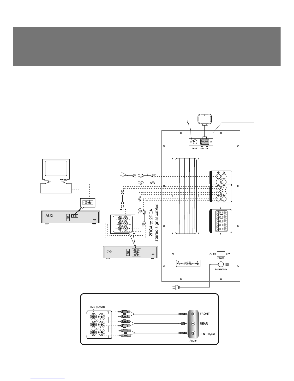
Audio Source Selection
• There are two stereo inputs (DŽDž, AUX) and 5.1CH input in the Home Theatre Speaker System.
To listen to a stereo audio source, connect it to AUDIO INPUT (k, Fig. 2) of the speaker system, as
shown in Fig. 5. To listen to a multichannel sound source, connect its multichannel output to 5.1CH
INPUT (l, Fig. 2) of the speaker system (see connection diagram, Fig. 5). Depending on the required
connection, select the desired audio source with the INPUT button on the control panel of the
subwoofer (d, Fig. 1) or with the DVD b, PC cor AUX dbuttons (Fig. 3) on the remote control.
The subwoofer display will illuminate with a corresponding inscription.
Turning on and Setting the Tuner
• Press the SCAN qand FM/AM sbuttons on the remote control to turn on the tuner and select
the FM or AM band.
• Manual setting. Press the TUNE + or TUNE- buttons ron the remote control for ԛne-tuning the
frequency of the radio station.
• Auto search. By holding SCAN qon the remote control for more than 1 second, turn on the
scanning of the FM band starting with 87 MHz frequency, the found radio stations being memorized
sequentially: «CH 01», «CH 02», «CH 03», etc. Scanning of the FM band will continue until 108 MHz
frequency. After the scanning, the ԛrst found radio station turns on.
• Additionally, you can turn on the desired broadcast quickly with the numeric keypad buttons (h
and i) on the remote control, having saved systems of 20 FM radio stations and 20 AM radio
stations.To save the found radio station, press MEMORY ton the remote control (CH _ _ will
illuminate on the display), then enter its number (from 0 to 19) with the numeric keypad buttons (h
and i) on the remote control, which will illuminate on the display (for example, CH 09). After
saving the required quantity of radio stations, enter the number of your desired radio station on the
remote control with the numerical keypad buttons (hand i) for quick search.
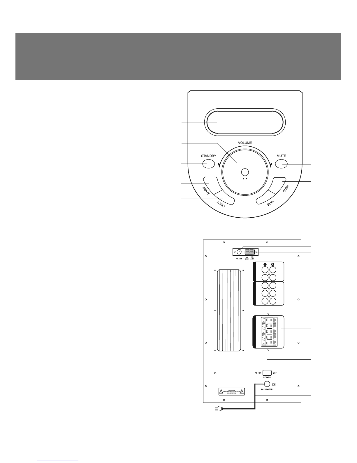
Master Volume Control
• Press VOL+ or VOL– (m, Fig. 3) on the remote control or turn the VOLUME knob (b, Fig. 1) on the
front panel of the subwoofer to adjust (increase/decrease) the volume level.
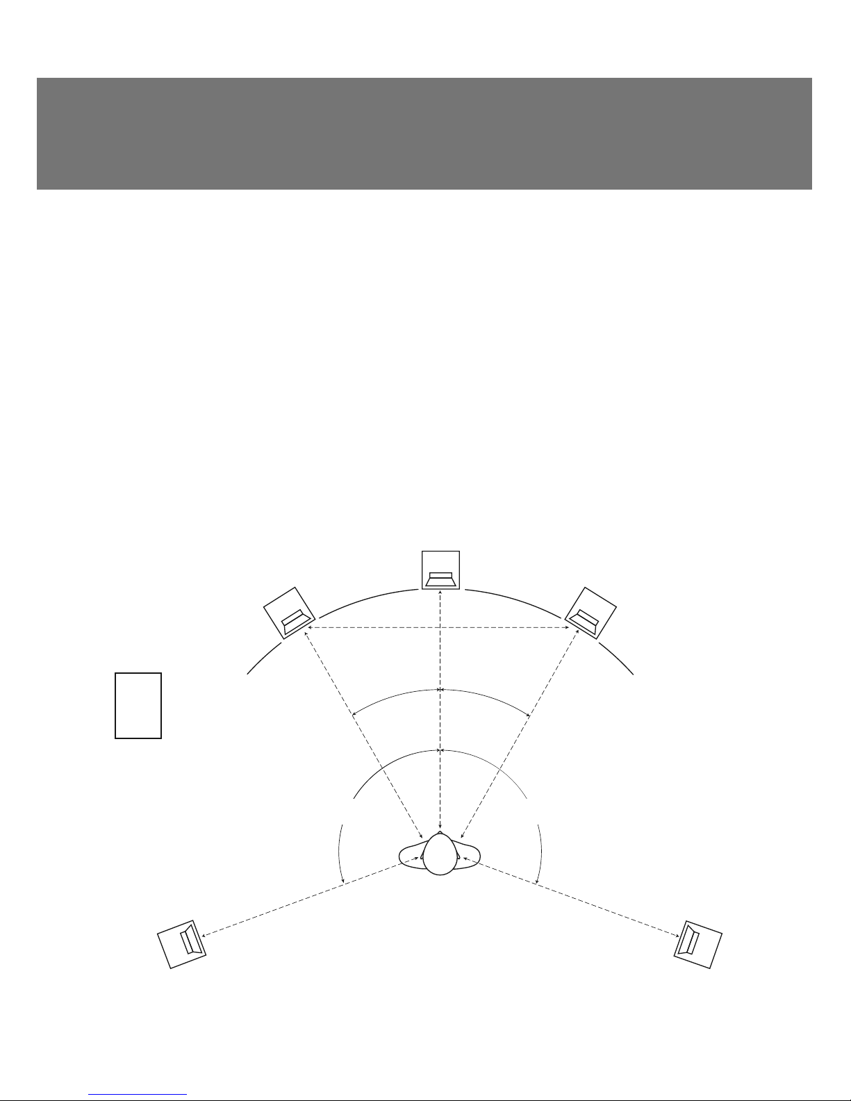
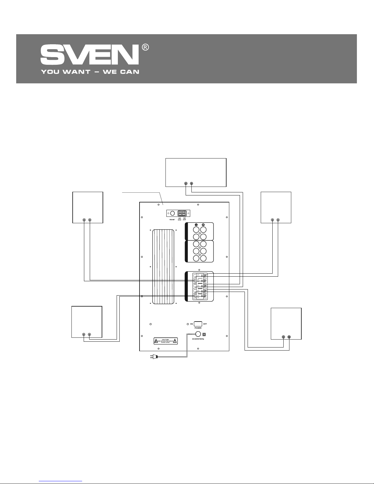
Satellites and Subwoofer Volume Control
• The volume level of the front, rear and center channel satellites can be adjusted with FRONT+/- f,
SURROUND+/- eand CEN+/- non the remote control. While SUB+/– oon the remote control or
SUB+ gand SUB– hon the control panel of the subwoofer (see Fig. 1) can adjust the subwoofer
volume level.
2D/3D sound
• To select between 2D and 3D sound modes, press the 2.1/5.1 button (l, Fig. 3) on the remote
control or the subwoofer control panel (e, Fig. 1), while your audio source is on. 3D or 2D mode
inscription will illuminate on the display according to the selected mode. If 5.1 audio source (DVD)
is connected and on, this feature is unavailable.
Mute feature
• Press MUTE jon remote control or button MUTE fon control panel of subwoofer to tempo-
rarily turn oԚthe sound. Press this button again to turn on the sound.
Note. If the speaker system is left unused for a long time, mind to switch off the device by
using POWER On/Off switch and unplug it.
ENG
9
Operation Manual BTR5-10

6. TROUBLESHOOTING
If none of the above methods can solve the problem, please seek professional advice at your
nearest service center. Never attempt to repair the product yourself.
Problem
The HTSS does
not turn on.
No sound.
There is too quiet
sound of speakers.
Distortion of
sound.
The remote control
is not working.
The FM/AM tuner
is not working.
Cause
The HTSS isn’t connected to a mains
outlet.
The power switch is oԚ.
Volume level is set at minimum value.
Improperly connected audio source.
Volume level is set at minimum value.
Large amplitude of the input signal.
The battery is discharged.
There is direct sunlight.
Obstacle between the remote control and
the subwoofer receiver.
The FM/AM tuner is not connected.
Poor reception of antennas.
Solution
Check the connection.
Turn on the switch.
Adjust volume control knob.
Connect audio sources correctly.
Adjust the volume control knob.
Turn down the source volume
and the HTSS volume.
Replace the battery with a new one.
Change the subwoofer or remote
control location.
Change the subwoofer or remote
control location.
Connect the FM/AM antenna.
Connect an external FM antenna
or an AM antenna.
ENG
10
5.1 Active Home Theater
Speaker System

Frequency bands:
АМ (at 9 kHz step), kHz
FМ(at 100 kHz step), MHz
S/N ratio:
AM, dB
FМ, dB
522 ~ 1611
87 ~ 108
> 45
> 45
Speaker system
Tuner
Output power (RMS), W
Rated load resistance
(per channel), Ohm
Frequency response, Hz
S/N ratio, dB
Speaker diameters, mm
Dimensions (W × H × D), mm
Power supply, V/Hz
Weight, kg
subwoofer
satellites
subwoofer
satellites
subwoofer
satellite (center)
satellites (front, rear)
subwoofer
satellite (center)
satellites (front, rear)
60
5 × 15
6
4
40 – 20 000
≥83
Ø 165
Ø 38 + 2 × Ø 100
Ø 38 + Ø 100
220 × 400 × 300
400 × 150 × 240
240 × 150 × 140
~230/50
21.5
Parameter, measurement unit Value
7. TECHNICAL SPECIFICATIONS
Notes:
•Technical specifications given in this table are supplemental information and cannot give
occasion to claims.
•Technical specifications and package contents are subject to change without notice due
to the improvement of SVEN production.
ENG
11
Operation Manual BTR5-10

ǀǢǘǙǟǰ:
BTR5-10
ƼǠǣǢǤǦǙǤ ǖDŽǢǥǥǜǜ: ǂǂǂ «DžƾƴǁƸƼdžDŽƹƿ», 111024,
DŽLj, Ǘ. ǀǢǥǞǖǔ, ǧǟ. ƴǖǜǔǠǢǦǢǤǡǔdz, ǘ. 65, ǥǦǤ. 1.
LJǣǢǟǡǢǠǢǫǙǡǡǔdz ǢǤǗǔǡǜǛǔǪǜdz ǖDŽǢǥǥǜǜ: ǂǂǂ «DŽdž-Lj»,
105082, Ǘ. ǀǢǥǞǖǔ, ǧǟ. LjǤǜǘǤǜǩǔ ǑǡǗǙǟǰǥǔ, ǘ. 75, ǥǦǤ. 5.
LJǥǟǢǖǜdz ǗǔǤǔǡǦǜǝǡǢǗǢ ǢǕǥǟǧǚǜǖǔǡǜdz ǥǠǢǦǤǜǦǙ
ǖǗǔǤǔǡǦǜǝǡǢǠ ǦǔǟǢǡǙ ǜǟǜ ǡǔ ǥǔǝǦǙ www.sven.ѵ
.
ƷǔǤǔǡǦǜǝǡǯǝ ǥǤǢǞ: 12 ǠǙǥ. DžǤǢǞ ǥǟǧǚǕǯ: 5 ǟǙǦ.
ǃǤǢǜǛǖǢǘǜǦǙǟǰ: «Džƶƹǁ ǃdžƹ. ƿǜǠǜǦǙǘ», 176
Ƹǚǧ NjǜǔǦ DŽǢǧǘ, д02-02, DžǜǡǗǔǣǧǤ, 427447.
ǃǤǢǜǛǖǙǘǙǡǢ ǣǢǘ ǞǢǡǦǤǢǟǙǠ «DžǖǙǡ DžǞǔǡǘǜǡǔǖǜdz
ƿǜǠǜǦǙǘ», 48310, Ljǜǡǟdzǡǘǜdz, ƾǢǦǞǔ, ƾǢǦǢǟǔǩǘǙǡǦǜǙ, 15.
DžǘǙǟǔǡǢ ǖƾǜǦǔǙ.
Manufacturer: SVEN PTE. LTD, 176 Joo Chiat Road,
д02-02, Singapore, 427447. Produced under the
control of Oy Sven Scandinavia Ltd. 15, Kotolahdentie,
Kotka, Finland, 48310. Made in China.
® Registered Trademark of Oy SVEN
Scandinavia Ltd. Finland.
2.0 Multimedia Speaker System
Automatic Voltage Regulator
DžǦǔǕǜǟǜǛǔǦǢǤ ǡǔǣǤdzǚǙǡǜdzDžǦǔǕǜǟǜǛǔǦǢǤ ǡǔǣǤdzǚǙǡǜdz
Automatic Voltage Regulator
2.0 Multimedia Speaker System2.0 Multimedia Speaker System
SPS-619
BTR5-10
5.1 Active Home Theater
Speaker System
Table of contents
Other Sven Speakers System manuals