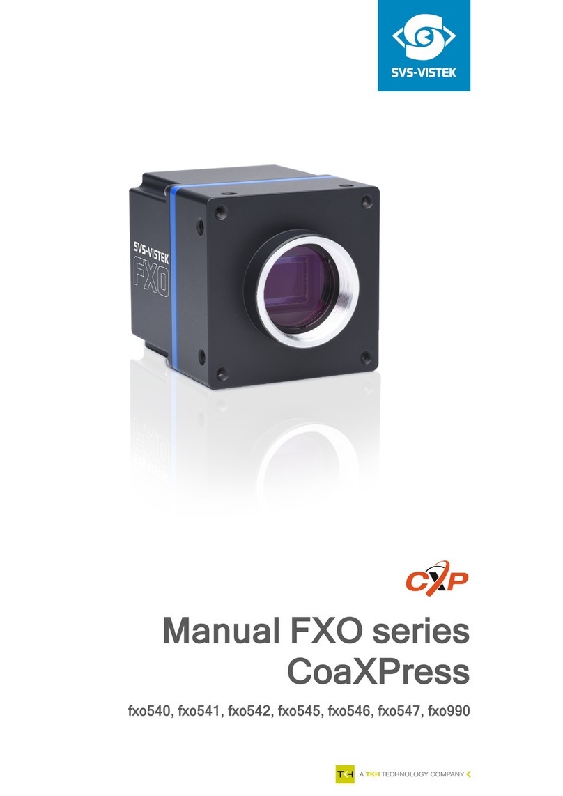
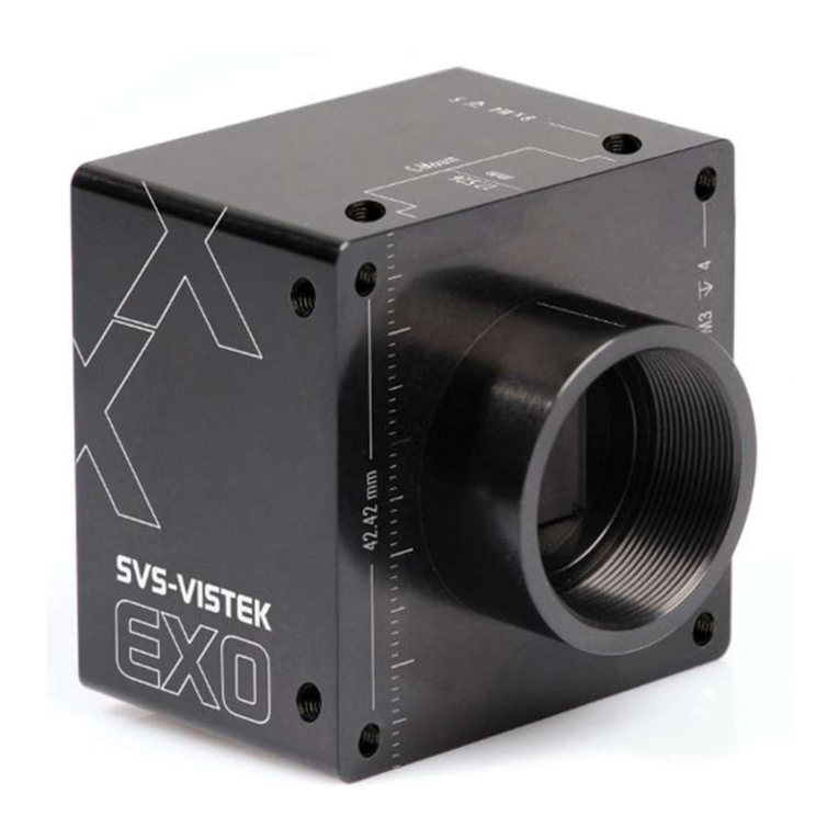
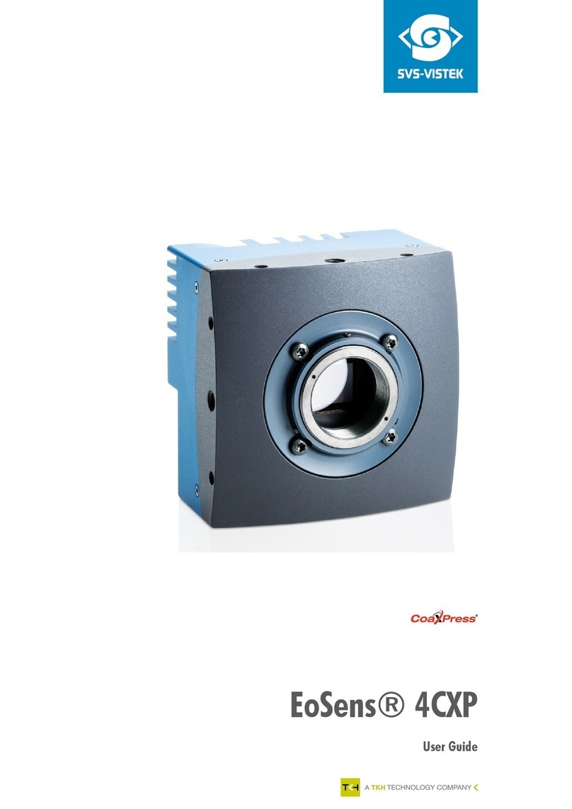
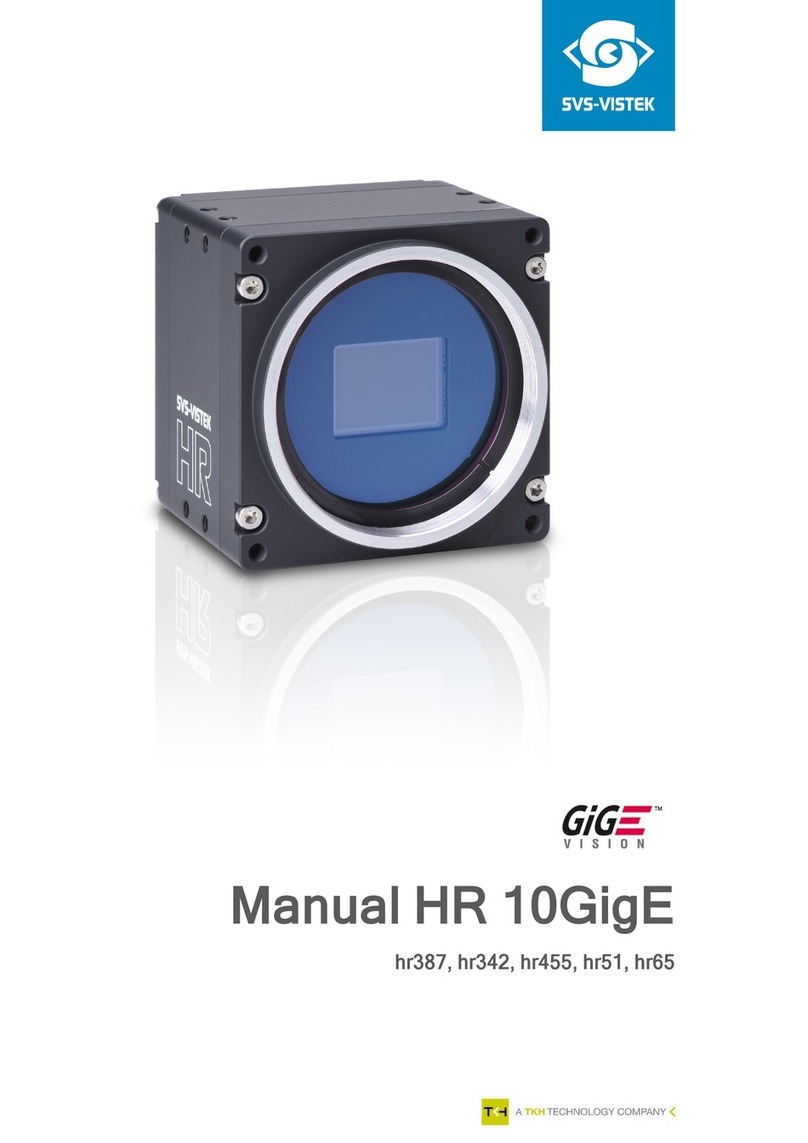
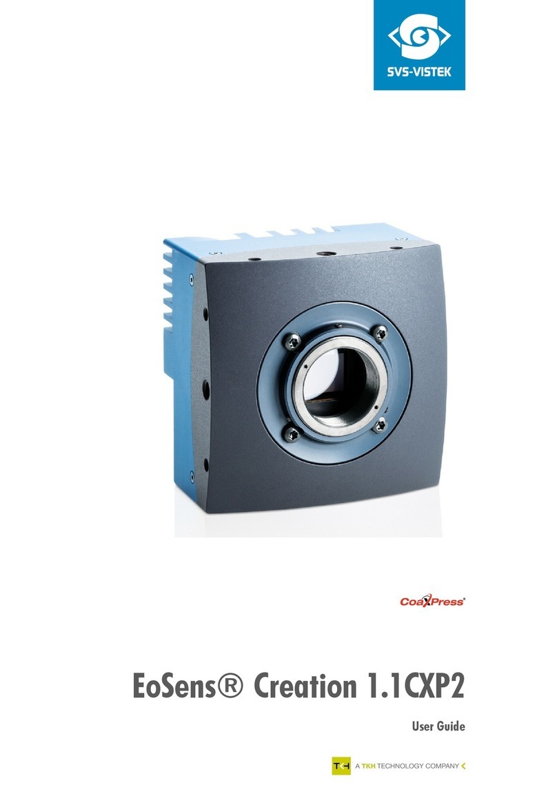
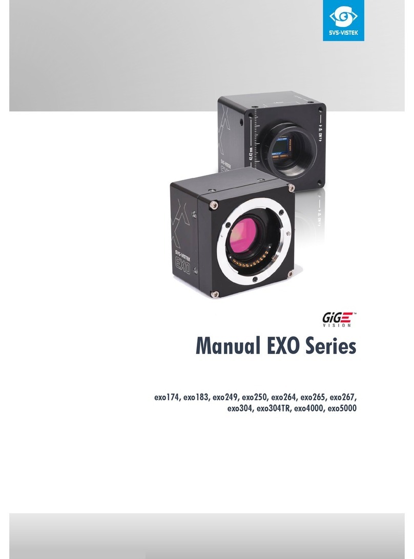
SVS-Vistek exo174 U3 Series User manual

1.23.2018
Manual EXO series
exo174*U3, exo183*U3, exo249*U3, exo250*U3,
exo252*U3, exo253*U3, exo255*U3, exo264*U3,
exo265*U3, exo267*U3, exo304*U3, exo4000*U3

Manual EXO series 1.23.2018
Company Information
SVS-VISTEK GMBH
Mühlbachstr. 20
82229 Seefeld
Germany
Tel.: +49 (0) 81 52 9985-0
Fax: +49 (0) 81 52 9985-79
Mail: info@svs-vistek.com
Web: http://www.svs-vistek.com
This Operation Manual is based on the following standards:
DIN EN 62079
DIN EN ISO 12100
ISO Guide 37
DIN ISO 3864-2
DIN ISO 3864-4
This Operation Manual contains important instructions for safe and
efficient handling of SVCam Cameras (hereinafter referred to as
„camera“). This Operating Manual is part of the camera and must be
kept accessible in the immediate vicinity of the camera for any person
working on or with this camera.
Read carefully and make sure you understand this Operation Manual
prior to starting any work with this camera. The basic prerequisite for safe
work is compliant with all specified safety and handling instructions.
Accident prevention guidelines and general safety regulations shoud be
applied.
Illustrations in this Operation Manual are provided for basic
understanding and can vary from the actual model of this camera. No
claims can be derived from the illustrations in this Operation Manual.
The camera in your possession has been produced with great care and
has been thoroughly tested. Nonetheless, should you have reasons for
complaint, then please contact your local SVS-VISTEK distributor. You will
find a list of distributors in your area under: http://www.svs-
vistek.com/company/distributors/distributors.php
Copyright Protection Statement
(as per DIN ISO 16016:2002-5)
Forwarding and duplicating of this document, as well as using or
revealing its contents are prohibited without written approval. All rights
reserved with regard to patent claims or submission of design or utility
patent.

Contents
iii
Contents
1
Safety Messages ......................................................6
2
Legal Information.....................................................7
3
The EXO.................................................................8
3.1
Building blocks simplify design-in................................ 8
3.1.1 Exclusive body architecture ............................................ 8
3.1.2 Form follows requirements............................................. 8
3.2
The EXO with USB3 Vision......................................... 9
3.3
4IO adds Light and Functionality.............................. 10
4
Getting Started ......................................................11
4.1
Power supply......................................................... 11
4.2
USB Flashing LED Codes ........................................ 11
4.3
Software............................................................... 12
4.3.1 SVCapture 2.x ............................................................ 12
4.4
Driver Circuit Schematics ........................................ 19
5
Connectors ........................................................... 20
5.1
USB3 Vision.......................................................... 20
5.2
Input / output connectors ........................................ 21
6
Dimensions ........................................................... 22
6.1
exo174*U3, exo249*U3......................................... 23
6.2
exo4000*U3......................................................... 27
6.3
exo183*U3, exo250*U3, exo252*U3, exo264*U3,
exo265*U3.................................................................... 31
6.4
exo255*U3, exo267*U3......................................... 35
6.5
exo253*U3, exo304*U3......................................... 38
6.6
C & CS Mount ...................................................... 41
7
Feature-Set ........................................................... 42
7.1
Basic Understanding............................................... 42
7.1.1 Basic Understanding of CMOS Technology................... 42
7.1.2 Global shutter ............................................................ 45
7.1.3 Rolling Shutter ............................................................ 46
7.1.4 Frames per Second ..................................................... 49
7.1.5 Acquisition and Processing Time .................................. 49
7.1.6 Exposure .................................................................... 50
7.1.7 Auto Luminance.......................................................... 50
7.1.8 Bit-Depth ................................................................... 51

Contents
iv
7.1.9 Color......................................................................... 53
7.1.10 Resolution – active & effective ...................................... 54
7.1.11 Offset ........................................................................ 55
7.1.12 Gain.......................................................................... 56
7.1.13 Image Flip.................................................................. 57
7.1.14 Binning ...................................................................... 58
7.1.15 Burst Mode ................................................................ 59
7.2
Camera Features................................................... 60
7.2.1 System Clock Frequency .............................................. 60
7.2.2 Temperature Sensor .................................................... 60
7.2.3 Basic Capture Modes.................................................. 61
7.2.4 LookUp Table............................................................. 64
7.2.5 ROI / AOI.................................................................. 66
7.3
I/O Features ......................................................... 66
7.3.1 Assigning I/O Lines – IOMUX ...................................... 66
7.3.2 Strobe Control............................................................ 73
7.3.3 Sequencer.................................................................. 80
7.3.4 PWM ......................................................................... 82
7.3.5 Optical Input.............................................................. 83
7.3.6 PLC/Logical Operation on Inputs ................................. 85
7.3.7 Serial data interfaces................................................... 86
7.3.8 Trigger-Edge Sensitivity................................................ 89
7.3.9 Debouncing Trigger Signals......................................... 89
7.3.10 Prescale ..................................................................... 91
7.4
IR Cut Filter........................................................... 92
8
Specifications ........................................................ 94
1.1
EXO174*U3 ......................................................... 95
8.1
EXO183*U3 ......................................................... 98
8.2
EXO249*U3 ....................................................... 100
1.1
EXO250*U3 ....................................................... 104
8.3
EXO252*U3 ....................................................... 106
8.4
EXO253*U3 ....................................................... 110
8.5
EXO255*U3 ....................................................... 113
8.6
EXO264*U3 ....................................................... 116
8.7
EXO265*U3 ....................................................... 119
8.8
EXO267*U3 ....................................................... 122
8.9
EXO304*U3 ....................................................... 125
8.1
EXO4000*U3 ..................................................... 127
9
Terms of warranty ................................................ 131
10
Troubleshooting................................................ 132
10.1
FAQ ............................................................... 132
10.2
Support Request Form / Check List ...................... 133
11
IP protection classes .......................................... 135
12
Glossary of Terms ............................................. 136
Contents
v
13
Index of figures ................................................. 139
14
Index ............................................................... 142

SVS-VISTEK–
Building
blocks simplify design-in 6
1Safety Messages
The classification of hazards is made pursuant to ISO 3864-2 and ANSI
Y535.6 with the help of key words.
This Operating Manual uses the following Safety Messages:
Risk of death or serious injury
DANGER!
Danger indicates a hazard with a high level of risk which, if not
avoided will result in death or serious injury.
WARNING!
Warning indicates a hazard with a medium level of risk which, if
not avoided will result in death or serious injury.
CAUTION!
Caution indicates a hazard with a low level of risk which, if not
avoided will result in death or serious injury.
Risk of damage
PROHIBITION!
A black graphical symbol inside a red circular band with a red
diagonal bar defines a safety sign that indicates that an action
shall not be taken or shall be stopped.
CAUTION!
A black graphical symbol inside a yellow triangle defines a
safety sign that indicates a hazard.
MANDATORY ACTION!
A white graphical symbol inside a blue circle defines a safety
sign that indicates that an action shall be taken to avoid a
hazard.
Cross-reference
NOTICE
Provides references and tips
Figure 1: Table of safety messages

SVS-VISTEK–Legal Information
Building
blocks simplify design-in 7
2Legal Information
Information given within the manual accurate as to: January 23, 2018,
errors and omissions excepted.
These products are designed for industrial applications only. Cameras
from SVS-Vistek are not designed for life support systems where
malfunction of the products might result in any risk of personal harm or
injury. Customers, integrators and end users of SVS-Vistek products might
sell these products and agree to do so at their own risk, as SVS-Vistek will
not take any liability for any damage from improper use or sale.
Europe
This camera is CE tested, rules of EN 55022:2010+AC2011 and
EN61000-6-2:2005 apply.
The product is in compliance with the requirements of the following
European directives:
2014/30/EU Electromagnetic compatibility (EMC)
2011/65/EU Restriction of the use of certain hazardous substances
in electrical and electronic equipment (RoHS)
All SVS-VISTEK cameras comply with the recommendation of the
European Union concerning RoHS Rules
USA and Canada
This device complies with part 15 of the FCC Rules. Operation is subject
to the following conditions: (1) This device may not cause harmful
interference, and (2) this device must accept any interference received,
including interference that may cause undesired operation.
Warning: This equipment is compliant with Class A of CISPR 32. In a
residential environment this equipment may cause radio interference.
This equipment has been tested and found to comply with the limits for a
Class A digital device, pursuant to part 15 of the FCC Rules.
It is necessary to use a shielded power supply cable. You can then use the
“shield contact” on the connector which has GND contact to the camera
housing. This is essential for any use. If not done and camera is destroyed
due to Radio Magnetic Interference (RMI) WARRANTY
is void
!
•
Power:
US/UK and European line adapter can be
delivered. Otherwise use filtered and stabilized DC power
supply.
•Shock & Vibration Resistance
is tested: For detailed
Specifications refer to Specification
.

SVS-VISTEK–The EXO
Building
blocks simplify design-in 8
3The EXO
The EXO series features a perfect match with its sophisticated, rugged
unibody housing and rich camera feature set, combined with industry
standard interfaces such as GigE Vision, Camera Link and USB3 Vision. A
smart solution for virtually any application, allowing smooth and effortless
up- or downscaling of machine vision applications. The EXO is easy to
integrate and comes with a full package of useful hardware features.
3.1 Building blocks simplify design-in
3.1.1 Exclusive body architecture
The EXO-Series comes in a new 50 x 50 mm aluminum body. The
elaborate, high precision machined unibody housing ensures perfect
temperature distribution even for the most demanding sensors. The
electric circuitry of the EXO is optimized for low power dissipation, helped
by the excellent temperature performance of the housing. The EXO
features the latest global shutter CMOS and CCD sensors from SONY,
CMOSIS and ON Semi.
3.1.2 Form follows requirements
A uniform form factor and identical standard interface connectors with
identical pinout facilitate interchangeability, allowing system integrators to
adapt applications with varying conditions and requirements very quickly
with minimum design effort. The massive lens mount is designed to keep
any kind of lens in its proper position.

SVS-VISTEK
The EXO 9
3.2 The EXO with USB3 Vision
is one of the most flexible and scalable cameras for the industrial market
segment. The USB3 Vision interface is easy to integrate in your system,
with a data rate up to effective 350 MB/sec. Power the camera via the
interface and reduce cable complexity.
>Up to 620 MB/sec brutto transfer rate
>Leverages existing infrastructure for cables and connectors
>GenICam compliant
>Cost effective / Easy implementation and interfacing
USB3 issues
Make sure your USB3 hardware is able to transfer the high data rates your camera
delivers.
In Theory, USB3.0 transfer rate is 5Gbps, USB3.1 even can transfer
10Gbps.
Despite being standardized, we find a significant amount of USB3
hardware being sold still is not capable to cope with these high data
rates. This refers to some USB3 host chipsets, USB hubs as well to high
processing load in the host computer. An integrated hardware buffer in
the SVS-Vistek camera (240MB in size) will try to catch and buffer these
cases. Burst Mode frame rate is limited to maximum USB speed. The
SVCapture GUI will show the real data rate of successful transfers. If you
encounter image losses, it might be whorthwhile to run the same camera
task with different USB chipsets and/or processor.
Generally,
>use a dedicated USB3 port at your computer
>do not use USB3 hubs for your image USB stream
>connect only the camera to this USB3 port
>in case of image drops, try different hardware or reduce frame rate
If the client hardware is too slow (processing load) the above is valid as
well.

SVS-VISTEK
The EXO 10
3.3 4IO adds Light and Functionality
Your SVS-Vistek camera is equipped with the innovative 4IO-interface
allowing full light control, replacing external strobe controllers. Each of
the outputs can be individually configured and managed using pulse-
width modulation. With its high current output, the camera is able to drive
LED lights directly without external light controller.
If you attach any light to the camera, make sure the power supply has
enough power not to fail when the camera is putting light ON.
The integrated sequencer allows multiple exposures with settings to be
programmed, creating new and cost effective options. Logical functions
like AND / OR are supported.
>Up to 4 x open drain high power OUT
>Up to 4 x high voltage IN – TTL up to 25 Volts
>Power MOSFET transistors
>PWM strobe control
>Sequencer for various configurations
>PLC fuctionality with AND, OR and timers
>Safe Trigger (debouncer, prescaler, high low trigger)
Figure 2: 4IO concept with up to 4 switching LED lights

SVS-VISTEK–Getting Started
Power
supply 11
4Getting Started
4.1 Power supply
Connect the power supply.
CAUTION! –This camera does not support hotplugging
1. First, connect the data cable.
2.
Then
connect power supply.
When using your own power supply (e.g. 10 -25 V DC) see also Hirose
12-pin for a detailed pin layout of the power connector. For power input
specifications refer to specifications.
4.2 USB Flashing LED Codes
On power up, the camera will indicate its current status with a flashing
LED on its back. The LED will change color and rhythm.
The meaning of the blinking codes translates as follows:
Figure 3: Status LED flashing codes
Flashing
Description
Yellow slow (1Hz)
No Connection
Yellow permanent
Network address assigned
Green slow (1Hz)
Streaming channel
available
Green quickly ( 8 Hz)
Acquisition enabled
Red slow ( 1 Hz )
Problem with initialization
Red quickly ( 8 Hz)
Camera overheating
Blue permanent
Waiting for trigger
Cyan permanent
Exposure active
Violet permanent
Readout/FVAL

SVS-VISTEK
Getting Started 12
4.3 Software
Further information, documentations, release notes, latest software and
application manuals can be downloaded in the download area on:
https://www.svs-vistek.com/en/login/svs-loginarea-login.php
Depending on the type of camera you bought, several software packages
apply.
4.3.1 SVCapture 2.x
Your SVCam combined software installer including:
>SVCapture 2.x
(a viewer/controler program for SVCam USB3 cameras)
>PC USB3 driver & filter driver
>TL_Driver
(GenICam drivers and transport layer DDLs)
SVCapture 2.x is a XML based software tool provided for free. It is created
to show the capabilities of your SVS-Vistek camera and to show/modify
values to your cam.
Get control of exposure timing, trigger delay, image correction etc. or
control up to 4 LED lights connected to the SVCam directly via the PC.
Use the built-in sequencer to program several intervals executed by one
single trigger impulse.
Figure 4: Screenshot of SVCapture 2.x

SVS-VISTEK
Getting Started 13
Software Setup
Installation prosecco may differ from PC to PC. It is recommended to
install the whole software package.
1. Copy/expand the installation executable file to your hard drive.
2. Run installation
3. Read and accept the terms of license agreement
4. Choose destination folder

SVS-VISTEK
Getting Started 14
5. Install the USB 3.0 Driver
Generic driver included in the windows system will not
match all SVS-VISTEK USB3 Vision features.
6. Start installation
7. System, warning
The installer will modify your system (USB 3.0 driver);
there for windows systems will warn you with an
interrupt.
Accept system modification

SVS-VISTEK
Getting Started 15
Installation will proceed
8. Installation completed

SVS-VISTEK
Getting Started 16
Initialization
FIRST LAUNCH
The software is XML based. So in case there is no Camera connected to
the USB slot, no XML camera properties can be loaded, no values to
control are available.
The screen will be empty.
Connect the camera to your USB 3.0 slot.
Hardware installation will pop up.
Discover the camera with SVCapture 2.x by clicking “discover”.
Connected cameras will be listed.
Choose your camera.

SVS-VISTEK
Getting Started 17
Conform to GenICam all control features will be listed in a flat tree
diagram.

SVS-VISTEK
Getting Started 18
USB 3.0 driver
The USB 3.0 driver
You can find the USB 3.0 driver within your hardware manager:
Firmware update
From time to time make sure your camera is running up to date firmware.
A firmware update tool is integrated in the software.
Internet connection needed.
In case there is no connection contact your local support:

SVS-VISTEK
Getting Started 19
4.4 Driver Circuit Schematics
Figure 5: basic Illustration of driver circuit

SVS-VISTEK–Connectors
USB3
Vision 20
5Connectors
5.1 USB3 Vision
The USB3 Vision interface is based on the standard USB 3.0 interface and
uses USB 3.0 ports.
If you drive the camera as a light controller (see chapter 4IO) depending
on the current the light is pulling it might be necessary to power the
camera with an external power supply as standard USB3 devices are
limited in their current supply.
This manual suits for next models
34
Table of contents
Other SVS-Vistek Machine Vision System manuals

SVS-Vistek
SVS-Vistek CoaXPress fxo540 User manual

SVS-Vistek
SVS-Vistek hr387 Series User manual

SVS-Vistek
SVS-Vistek CoaXPress EoSens 21CXP2 User manual

SVS-Vistek
SVS-Vistek CoaXPress EoSens 4CXP User manual

SVS-Vistek
SVS-Vistek 10 GiGE FXO Series User manual

SVS-Vistek
SVS-Vistek CAMERA Link EoSens 3CL User manual

SVS-Vistek
SVS-Vistek SHR 10GigE User manual

SVS-Vistek
SVS-Vistek EoSens Creation 2.0XGE User manual

SVS-Vistek
SVS-Vistek shr 411 User manual

SVS-Vistek
SVS-Vistek exo174 User manual