SVS-Vistek shr 411 User manual

Manual SHR CoaXPress
shr411, shr461, shr661

Content
1 Company information 5
1.1 Standards 5
1.2 Disclaimer 5
1.3 Copyright notice 6
2 Legal information 7
2.1 USA and Canada 7
2.2 Europe 7
2 The SHR series 8
2.3 High precision with large pixels 8
2.4 CoaXPress features 8
2.5 4I/O adds light and functionality 9
3 Getting started 10
3.1 Get help 10
3.2 Find camera specs 10
3.3 Power supply 10
3.3.1 Power safety 10
3.3.2 Connect the camera 11
3.4 Camera status LED codes 11
3.5 Software and firmware 13
3.5.1 Software for CoaXPress 13
3.5.2 SVCapture 2.x 13
3.5.3 Software development kit 18
4 Connectors 19
4.1 CoaXPress 19
4.1.1 Protocol description 19
4.1.2 Connecting the data cable(s) 19
4.2 Hirose I/O connector 20
2

5 Feature description 21
5.1 Basic features 21
5.1.1 Gain 21
5.1.2 Resolution 22
5.1.3 Offset 22
5.1.4 Color 24
5.1.5 Flip image 25
5.1.6 Binning 26
5.1.7 Decimation 27
5.1.8 GenICam 29
5.1.9 Trigger modes 30
5.1.10 Shutter modes 33
5.1.11 Exposure 38
5.1.12 Exposure speed 39
5.1.13 Auto exposure 39
5.1.14 Acquisition and processing time 39
5.1.15 Bit depth 40
5.1.16 ROI / AOI 41
5.2 Camera features 42
5.2.1 Glass filter 42
5.2.2 Shading correction 42
5.2.3 Defect pixel correction 45
5.2.4 Look-up table 50
5.2.5 ROI / AOI 52
5.2.6 Basic capture modes 53
5.2.7 Trigger modes 55
5.2.8 Read-out control 57
5.2.9 Temperature sensor 57
5.2.10 System clock frequency 57
5.2.11 Predefined configurations (user sets) 58
5.3 I/O Features 60
5.3.1 GenICam 60
5.3.2 Assigning I/O Lines – IOMUX 61
5.3.3 PWM 67
5.3.4 LED strobe control 71
5.3.5 Sequencer 73
5.3.6 Optical input 78
5.3.7 PLC / Logical operation on inputs 78
5.3.8 Serial data interfaces 80
5.3.9 Trigger-edge sensitivity 81
5.3.10 Debouncing trigger signals 82
5.3.11 Prescale 84
3

1 Company information
SVS-Vistek GmbH
Ferdinand-Porsche-Str. 3
82205 Gilching
Germany
Tel.: +49 (0) 8105 3987-60
Fax: +49 (0) 8105 3987-699
Mail: inf[email protected]
Web: https://www.svs-vistek.com
1.1 Standards
This manual is based on the following standards:
lDIN EN 62079
lDIN EN ISO 12100
lISO Guide 37
lDIN ISO 3864-2
lDIN ISO 3864-4
lDIN ISO 16016:2002-5
1.2 Disclaimer
This manual contains important instructions for safe and efficient handling of
SVCam products. This manual is part of the product and must be kept access-
ible in the immediate vicinity of the product for any person working on or with
this product .
Read carefully and make sure you understand this manual prior to starting any
work with this product . The basic prerequisite for safe work is compliant with all
specified safety and handling instructions.
Accident prevention guidelines and general safety regulations should be
applied.
Illustrations in this manual are provided for basic understanding and can vary
from the actual model of this product . No claims can be derived from the illus-
trations in this manual.
The product in your possession has been produced with great care and has
been thoroughly tested. Nonetheless, in case of any complaint, please contact
your local SVS-VISTEK distributor. You will find a list of distributors in your area
on www.svs-vistek.com
1 Company information 5

1.3 Copyright notice
Forwarding and duplicating of this document, as well as using or revealing its
contents are prohibited without written approval. All rights reserved with regard
to patent claims or submission of design or utility patent.
1 Company information 6

2 Legal information
Errors and omissions excepted.
These products are designed for industrial applications only. Cameras from
SVS-Vistek are not designed for life support systems where malfunction of the
products might result in any risk of personal harm or injury. Customers, integ-
rators and end users of SVS-Vistek products might sell these products and
agree to do so at their own risk, as SVS-Vistek will not take any liability for any
damage from improper use or sale.
2.1 USA and Canada
This device complies with part 15 of the FCC Rules. Operation is subject to the
following conditions: (1) This device may not cause harmful interference, and
(2) this device must accept any interference received, including interference
that may cause undesired operation.
NOTICE This equipment is compliant with Class A of CISPR 32. In a residential
environment this equipment may cause radio interference.
This equipment has been tested and found to comply with the limits for a Class
A digital device, pursuant to part 15 of the FCC rules.
It is necessary to use a shielded power supply cable. You can then use the
“shield contact” on the connector which has GND contact to the device housing.
This is essential for any use. If not done and the device is destroyed due to
Radio Magnetic Interference (RMI) WARRANTY is void!
lPower: US/UK and European line adapter can be delivered. Otherwise use
filtered and stabilized DC power supply.
lShock & vibration resistance is tested. For detailed specifications refer to
the section on specifications ("Specifications").
2.2 Europe
This device is CE tested, rules of EN 55022:2010+AC2011 and EN61000-6-
2:2005 apply.
The product is in compliance with the requirements of the following European
directives:
l2014/30/EU Electromagnetic compatibility (EMC)
l2011/65/EU Restriction of the use of certain hazardous substances in elec-
trical and electronic equipment (RoHS)
All SVS-VISTEK products comply with the recommendation of the European
Union concerning RoHS Rules.
2 Legal information 7

2 The SHR series
2.3 High precision with large pixels
The SVCam SHR series is a series of industrial machine vision cameras fea-
turing especially on very high image resolutions with large pixels and global
shutter. In the industrial machine vision business, there are applications where
global shutter with high resolutions cannot permit compromises on image qual-
ity. This is the playground for the SHR.
Wide fields of view and global shutter make this camera series your prime
choice for demanding applications such as optical meteorology, aerial imaging
or scientific research. Global shutter reduces optical distortion on the sensor
side, large pixels reduce noise and extend the usable dynamic range.
One of the most compact camera modules of its class
SVS-VISTEK is introducing high-class sensors with high resolutions and large
pixels to generate high-resolution images in an outstanding quality. This covers
sophisticated CCD technology as well as latest CMOS sensors. High and ultra-
high resolutions with large pixels are challenging. We combine our advanced
knowledge in these areas with a robust I/O design and advanced industrial cam-
era layout, providing reliable excellence in industrial imaging.
Best imaging performance is possible only with excellent lenses. Nearly all
kinds of lenses can be adapted to the SHR due to its wide lens opening of
72 mm. Ask for adapters regarding your specific lens requirement.
2.4 CoaXPress features
CoaXPress (CXP) is the latest development regarding high speed high volume
data transfer for imaging. The interface needs a frame grabber. The CoaXPress
standard is very precise and is incorporating a lot of features like power-over-
CoaXPress (PoCXP) already in the standard definition.
Main advantages of CXP are
l6.25 Gbit/s transfer rate (CXP-6) per line
lLines can be teamed: a 4-line aggregation delivers up to 25 Gbit/s
lProvides data and power on a single line
lVery thin and flexible cables
l25m data cable supported
lExtremely low latency times
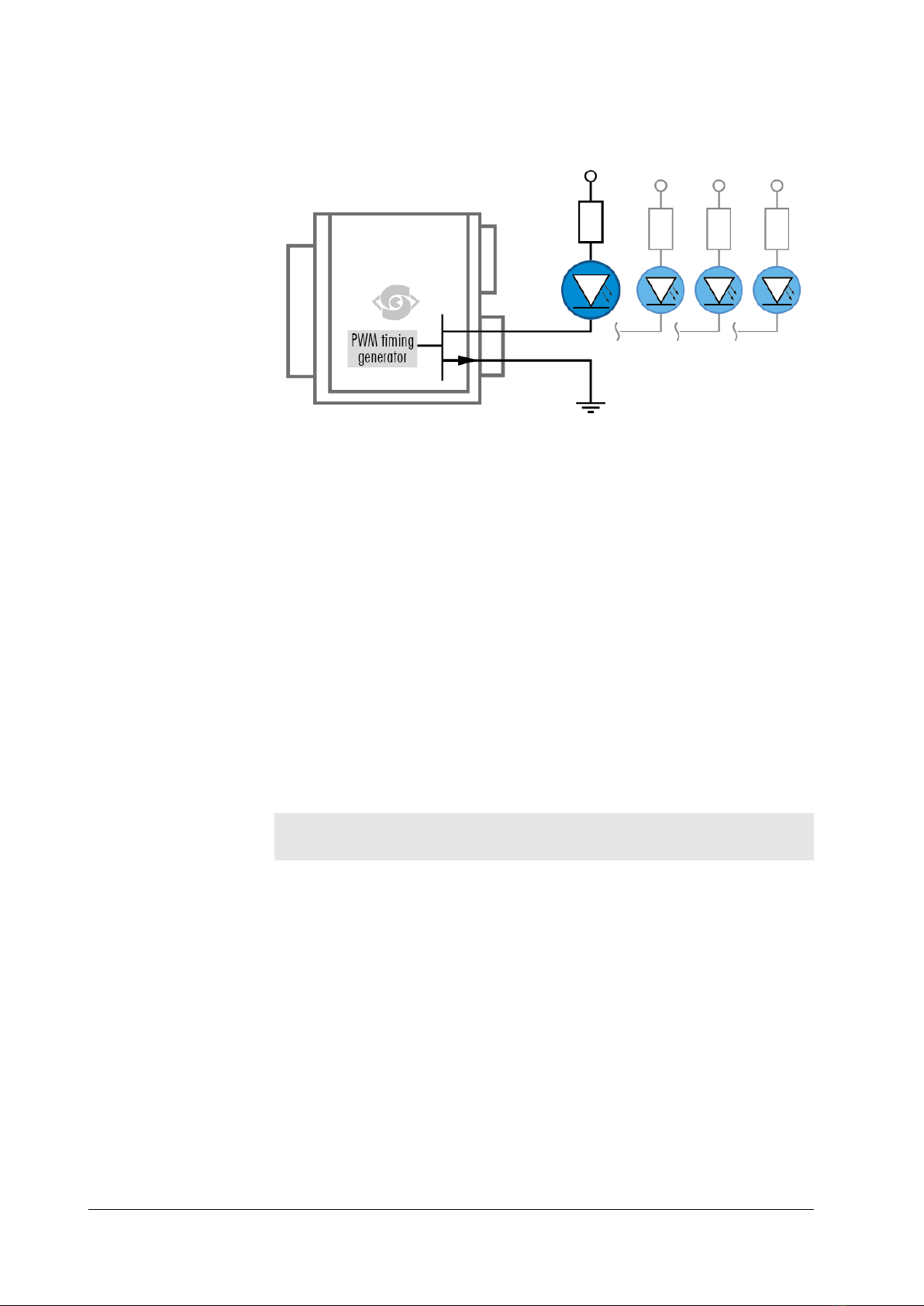
INFO If using the 4IO PWM outputs to drive lights, you need an external power sup-
ply as PoCXP is unable to deliver the high currents requested by the lights.
2 The SHR series 8

2.5 4I/O adds light and functionality
Fig.: 2-1: Illustration of 4I/O concept of switching LEDs
Your SVS-Vistek camera is equipped with the innovative 4I/O-interface allowing
full light control, replacing external strobe controllers. Each of the outputs can
be individually configured and managed using pulse width modulation. With its
high current output, the camera is able to drive LED lights directly without
external light controller.
The integrated sequencer allows multiple exposures with settings to be pro-
grammed, creating new and cost effective options. Logical functions like AND /
OR are supported.
lUp to 4 x open drain high power OUT
lUp to 4 x high voltage IN – TTL up to 25 Volts
lPower MOSFET transistors
lPWM strobe control
lSequencer for various configurations
lPLC fuctionality with AND, OR and timers
lSafe Trigger (debouncer, prescaler, high low trigger)
INFO Find an example how to operate light control in the section on sequencer
("Sequencer" on page 73).
2 The SHR series 9

3 Getting started
3.1 Get help
In case of issues with the camera we are happy to help. For being able to help
you in a fast and efficient way, we ask you for a description of the issues using
camera in your support request.
You can put your support request to us via our support form:
https://www.svs-vistek.com/en/support/svs-support-request.php
Please fill the form with special attention to camera model, frame grabber model
and operating system. Our support team will come back to you.
3.2 Find camera specs
Our website does have all technical data of all our cameras online. Go to
https://www.svs-vistek.com/en/industrial-cameras/svs-cameras.php for getting
technical data sheets.
Cameras can be found by searching with series and model name or by using
the SVCam camera finder. Having found the requested camera, the details/-
download section provides you with manuals, drawings, soft- and firmware for
your camera.
3.3 Power supply
For safety reasons, for protection of the camera and users, use certified power
supplies (Low power supply according IEC 62368-1) only. Please refer to spe-
cifications for your camera model. Appropriate power supplies can be ordered
at SVS-Vistek GmbH.
3.3.1 Power safety
The camera does not have a power switch. The camera is powered on as soon
power is available to the camera. This might happen via the Hirose connector or
(in case of USB or CoaXPress) through the interface cables.
For making sure the camera is not connected to power
lDisconnectHirose(orM12)plugfromcamera
lIfthecamerainterfaceisUSBorCoaXPress,disconnectinterfaceconnectorfromthecamera
lDisconnectpowerplugfrompowerACwalloutlettodisabletheDCpowersupplyaswell.
The power supply must be easily accessible at all times! For Power specs, refer
to the data sheet of your model.
Before connecting your camera to power, make sure your data cable is con-
nected properly. Always connect data cable before power.
3 Getting started 10

3.3.2 Connect the camera
The camera is powered on by connecting power to to the camera. Connect the
power supply with the Hirose connector. When using your own power supply
(voltage range 10 -25 V DC) see also Hirose™ 12-Pin layout of the power con-
nector. For power input specifications refer to specifications.
Generally external power supply for USB3 Vision, CoaXPress (if PoCXP
enabled) or PoE cameras is not needed. Nonetheless, you might want to use a
separate power on the Hirose connector to reduce load on the data port. The
external power on the Hirose connector is the preferred power source.
INFO Only power supply with external dedicated power supply is powering 4I/O LED
lights. Power supply via data lines covers camera supply only. If you want to
use the I/O-output lines to drive LED lights, the camera needs an external ded-
icated power supply on the Hirose connector.
The power up is defined as follows:
>Power over USB3, CoaXPress port or GigE port (with PoE) or on the Hirose
connector will power on the camera
>If power is found on the Hirose connector, camera power supply will switch
to the Hirose connector
>If Hirose power supply is cut, camera power supply will switch back to
power over USB3, PoE or power over CXP supply
When using your own power supply (voltage range 10-25 V DC) see also
Hirose 12- pin layout of the power connector. For power input specifications
refer to specifications.
Caution Camera Link cameras do not support hotplugging
3.4 Camera status LED codes
Latest SVCam CoaXPress cameras provides status information per CXP line. A
LED is located close to each CXP connector and will indicate the current status
for the appropriate CXP line. The LEDs will change color and rhythm.
The meaning of the CXP line blinking codes is depending whether PoCXP is
used and translates as follows:
3 Getting started 11

Fig.: 3-1: Camera status LED codes
3 Getting started 12

3.5 Software and firmware
Further information, documentations, release notes, latest software and applic-
ation manuals can be downloaded in the download area on SVS-Vistek down-
load area. Depending on the type of camera you bought, several software
packages apply.
If you are logged in, this is the location to find latest releases of firmware
upgrades of your camera model as well.
3.5.1 Software for CoaXPress
CoaXPress is a well defined standard protocol. As there is the need for a hard-
ware grabber, the grabber manufacturer is providing software for CoaXPress
cameras. Please refer to the manufacturer of your CoaXPress grabber device.
The latest SVCapture (starting with version 2.5.4) is able to run CoaXPress cam-
eras with Euresys CoaXPress interface cards and their GenTL drivers respect-
ively. SVCapture providing a GenICam interface tree with its GenICam
properties. You might need your framegrabber’s manufacturer software for view-
ing images though.
Please read the SVCam Kit Quick Guide regarding install.
3.5.2 SVCapture 2.x
SVCapture is the recommended, GenICam-based software to operate SVCam
industrial cameras. Your SVCam combined software installer including:
lSVCapture 2.x
(a viewer/controller program for SVCam cameras)
lPC USB3 driver & filter driver
lGenTL_Drivers
(GenICam drivers and transport layer DDLs for Camera Link, CoaXPress,
USB3, GigE / 10 GigE)
lC/C# programming libs and interface
SVCapture 2.x is a GenICam/XML based software tool provided for free. It is
created to show the capabilities of your SVS-Vistek camera and to show/modify
values to your cam.
Get control of exposure timing, trigger delay, image correction etc. or control up
to 4 LED lights connected to the SVCam directly via "GenICam" on page 60con-
trol. Use the built-in "Sequencer" on page 73to program several intervals
executed by a single trigger impulse.
3 Getting started 13

Fig.: 3-2: Screenshot of SVCapture 2.x: GenICam tree and current image
Setup of SVCapture2
Installation procedure may differ from PC to PC. It is recommended to install the
whole software package. For this step it is necessary to have root access to
your computer.
1. Copy or expand the installation executable file to your hard drive.
2. Start installation. Read and accept the terms of license agreement.
3. Choose destination folder and select necessary modules / drivers. The
TLxxx modules are the GenTL drivers, necessary as well if you want to use
3 Getting started 14

SVS-Vistek driver with third party software.
4. In case of system warnings regarding modification of USB3 drivers or
GigE/10GigE filter drivers: The specified performance is possible only with
these highly optimized drivers. Accept these modifications.
Initialization
First launch
1. Connect the camera to your computer. In case of a new USB3 camera
driver hardware installation notice will pop up.
3 Getting started 15

2. Start SVCapture. SVCapture will try to discover your camera.
3. Click on the camera being found and you’re connected.
Depending on your interface type, with TL Settings you are able to adjust which
interface types should be included in the camera discover process.
INFO If you have installed third-party GenTL drivers (e.g. Euresys CoaXPress or
Camera Link drivers), they should be selectable as well. This works only if
third-party software has been installed before SVCapture.
3 Getting started 16

4. Find and adjust your camera features in the GenICam tree. Click and
adjust items by number (1.) or slider (2.) and start grabbing images from
the camera.
USB 3.0 driver
You can find the USB 3.0 driver which has been installed automatically within
the hardware manager:
3 Getting started 17

3.5.3 Software development kit
The SDK is based on C programming language and is installed together with
SVCapture2. The SDK supports C and C++. For a typical installation, the lib-
raries, header files, and examples are located in the directory:
C:\Program Files\SVS-VISTEK GmbH\SVCam Kit\SDK
INFO Refer to the “Getting started with SDK” manual for first steps in programming
your SVS-Vistek camera. This document should be included in the docs sec-
tion of your installation.
The following platforms are supported:
lX86 (Windows, Linux, MacOS support on request)
lARM (Nvidia Jetson TX1/TX2)
3 Getting started 18

4 Connectors
Cameras from SVS-Vistek feature a combined I/O and power supply connector
(Hirose) and a data connector.
4.1 CoaXPress
4.1.1 Protocol description
CoaXPress was established as a standard protocol in machine vision 2009.
The current version documented by Japan Industrial Imaging Association is 1.1.
It is targeted to high bandwidth connections. The CoaXPress standard is scal-
able from 1.25 Gbit/s up to 25 Gbit/s with a maximum distance of more than
200 m.
The standard connector for CoaXPress is a 75Ω DIN 1.0/2.3 connector.
Depending on the desired bit rate, environment and speed you might use 75Ω
coaxial cables like RG11, RG6, RG59 and RG187 (recommended).
SVS-VISTEK uses female connectors on their cameras according to JIIA stand-
ard.
You need cables with male connectors (plugs).
Protocol type is serial and is designed as an end-to-end connection. Forwarding
the data stream to multiple receivers does require additional hardware (pls con-
tact SVS-VISTEK).
SVS-VISTEK cameras are supporting CoaXPress with up to 6.25 Gbit/s per
line. Transmission speeds above this can be managed by operating multiple
CoaXPress lines in parallel. Currently the cameras (depending on the model)
from SVS-VISTEK are supporting up to 4 lines in parallel. All SVS-VISTEK
CoaXPress cameras support the GEN<i>CAM interface.
CoaXPress standard supports camera control and power over CoaXPress
(PoCXP, 24 V@13W). It is recommended to use the frame grabber power sup-
ply over CoaXPress.
4.1.2 Connecting the data cable(s)
You need a CoaXPress frame grabber for connecting the camera to your host
computer.
Before powering on, connect the cables to the camera and the frame grabber.
CXP connectors have a locking mechanism. Always plug and unplug the cable
at the connector, never pull the cable.
If your frame grabber has got less channels than the camera, the data transfer
will not reach the maximum values mentioned in the specifications. If your
frame grabber has more CoaXPress lines than your camera, try to connect the
low channel numbers (0,1,…) first.
You may connect more than 1 camera to a multi-channel frame grabber. Always
connect the CoaXPress data cables before power on!
NOTICE Be careful with the tiny connectors. They slide up neatly and are locking
quite well, but too much force might easily break the connectors.
4 Connectors 19

4.2 Hirose I/O connector
The Hirose™ connector provides power, input and output signal access. Max
power out is 2 Amperes peak.
Fig.: 4-1: I/O Hirose connector layout
Inputs and outputs connect via 4I/O-matrix in the GenICam software tree to the
appropriate actions. For detailed information about switching lights with the
power outputs via GenICam, refer to "LED strobe control" on page 71.
Type HR10A-10R-12P
Matching Connector HR10A-10P-12S
Table: 4-1: Hirose connector types
INFO PoE (Power over Ethernet) models do not support RS232 on pins 3 & 4.
4 Connectors 20
This manual suits for next models
2
Table of contents
Other SVS-Vistek Machine Vision System manuals

SVS-Vistek
SVS-Vistek CoaXPress FXO Series User manual

SVS-Vistek
SVS-Vistek CoaXPress EoSens 4CXP User manual

SVS-Vistek
SVS-Vistek exo174 User manual

SVS-Vistek
SVS-Vistek CAMERA Link EoSens 3CL User manual

SVS-Vistek
SVS-Vistek EXO Series User manual

SVS-Vistek
SVS-Vistek CoaXPress fxo540 User manual

SVS-Vistek
SVS-Vistek exo174 U3 Series User manual

SVS-Vistek
SVS-Vistek CoaXPress EoSens 21CXP2 User manual

SVS-Vistek
SVS-Vistek hr387 Series User manual

SVS-Vistek
SVS-Vistek GIGA VISION ECO 4I/O User manual