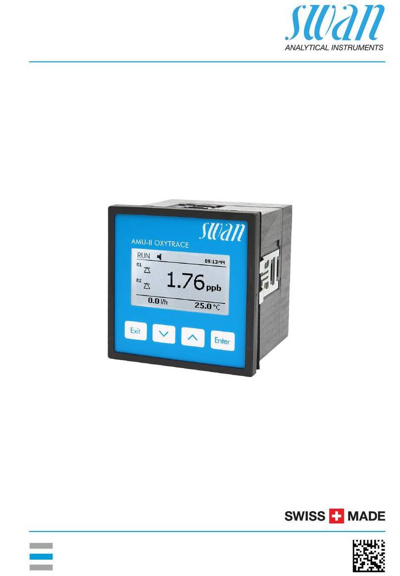
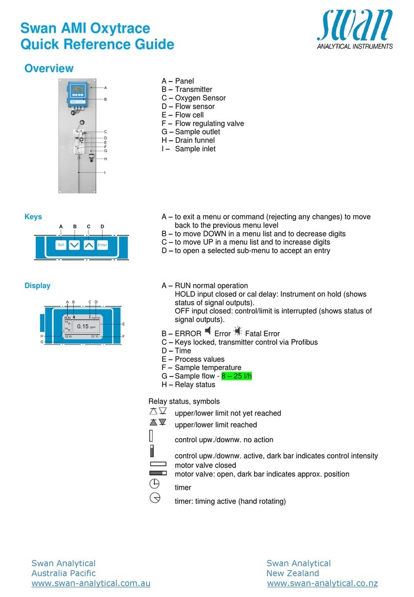
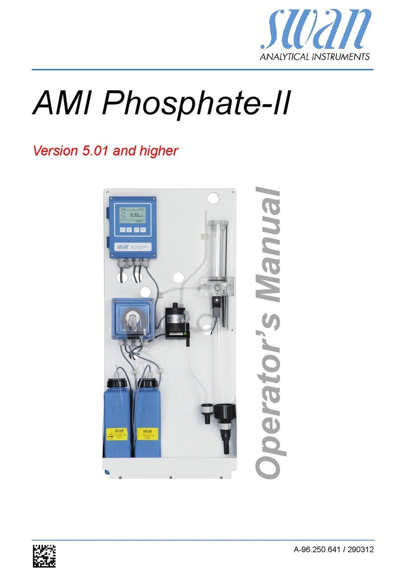
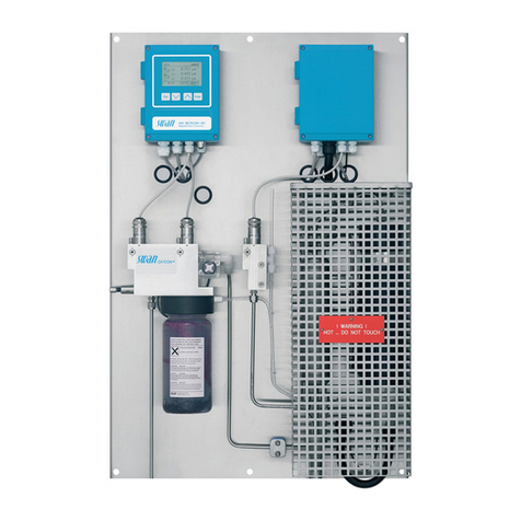
Swann AMU-II Pharmacon User manual

Operator’s Manual
Firmware V1.00 and higher
AMU-II Pharmacon
A-96.150.691 / 041021

© 2021, Swan Analytische Instrumente AG, Switzerland, all rights reserved.
The information contained in this document is subject to change without notice.
Customer Support
Swan and its representatives maintain a fully trained staff of technical specialists around
the world. For any technical question, contact your nearest Swan representative, or the
manufacturer:
Swan Analytische Instrumente AG
Studbachstrasse 13
8340 Hinwil
Switzerland
Internet: www.swan.ch
E-mail: [email protected]
Document Status
Title: AMU-II Pharmacon Operator’s Manual
ID: A-96.150.691
Revision Issue
00 Oct. 2021 First edition

A-96.150.691 / 041021
AMU-II Pharmacon
3
Table of contents
1. Safety Instructions . . . . . . . . . . . . . . . . . . . . . . . . . . . . . . . . . . . . . . . . . . . . . 5
1.1. Warning Notices . . . . . . . . . . . . . . . . . . . . . . . . . . . . . . . . . . . . . . . . . . . . . . . . 6
1.2. General Safety Regulations . . . . . . . . . . . . . . . . . . . . . . . . . . . . . . . . . . . . . . . 8
2. Product Description . . . . . . . . . . . . . . . . . . . . . . . . . . . . . . . . . . . . . . . . . . . . 9
2.1. Description of the System . . . . . . . . . . . . . . . . . . . . . . . . . . . . . . . . . . . . . . . . . 9
2.2. Single Components . . . . . . . . . . . . . . . . . . . . . . . . . . . . . . . . . . . . . . . . . . . . . . 11
2.2.1 AMU-II Pharmacon Transmitter . . . . . . . . . . . . . . . . . . . . . . . . . . . . . . . . . . . 11
2.2.2 Swansensor Pharmacon . . . . . . . . . . . . . . . . . . . . . . . . . . . . . . . . . . . . . . . . 12
3. Installation . . . . . . . . . . . . . . . . . . . . . . . . . . . . . . . . . . . . . . . . . . . . . . . . . . . . 16
3.1. Mounting of the AMU-II Transmitter . . . . . . . . . . . . . . . . . . . . . . . . . . . . . . . . . 16
3.2. Electrical Connections. . . . . . . . . . . . . . . . . . . . . . . . . . . . . . . . . . . . . . . . . . . . 18
3.3. Power Supply . . . . . . . . . . . . . . . . . . . . . . . . . . . . . . . . . . . . . . . . . . . . . . . . . . 19
3.4. Sensor . . . . . . . . . . . . . . . . . . . . . . . . . . . . . . . . . . . . . . . . . . . . . . . . . . . . . . . . 19
3.5. Swan Flow Meter. . . . . . . . . . . . . . . . . . . . . . . . . . . . . . . . . . . . . . . . . . . . . . . . 19
3.6. Input . . . . . . . . . . . . . . . . . . . . . . . . . . . . . . . . . . . . . . . . . . . . . . . . . . . . . . . . . 20
3.7. Relay Contacts . . . . . . . . . . . . . . . . . . . . . . . . . . . . . . . . . . . . . . . . . . . . . . . . . 20
3.7.1 Alarm Relay . . . . . . . . . . . . . . . . . . . . . . . . . . . . . . . . . . . . . . . . . . . . . . . . . . 20
3.7.2 Relay 1 and 2. . . . . . . . . . . . . . . . . . . . . . . . . . . . . . . . . . . . . . . . . . . . . . . . . 20
3.8. Signal Output 1 and 2 (Current Outputs). . . . . . . . . . . . . . . . . . . . . . . . . . . . . . 21
3.9. Interface Options . . . . . . . . . . . . . . . . . . . . . . . . . . . . . . . . . . . . . . . . . . . . . . . . 22
3.9.1 Installation . . . . . . . . . . . . . . . . . . . . . . . . . . . . . . . . . . . . . . . . . . . . . . . . . . . 22
3.9.2 USB Option . . . . . . . . . . . . . . . . . . . . . . . . . . . . . . . . . . . . . . . . . . . . . . . . . . 24
3.9.3 RS485 Option . . . . . . . . . . . . . . . . . . . . . . . . . . . . . . . . . . . . . . . . . . . . . . . . 25
3.9.4 HART Option . . . . . . . . . . . . . . . . . . . . . . . . . . . . . . . . . . . . . . . . . . . . . . . . . 25
3.10. RS232 Interface . . . . . . . . . . . . . . . . . . . . . . . . . . . . . . . . . . . . . . . . . . . . . . . . 26
3.11. Install the Swansensor Pharmacon SAN . . . . . . . . . . . . . . . . . . . . . . . . . . . . . 27
3.12. Install the Swansensor Pharmacon NPT. . . . . . . . . . . . . . . . . . . . . . . . . . . . . . 29
4. Instrument Setup. . . . . . . . . . . . . . . . . . . . . . . . . . . . . . . . . . . . . . . . . . . . . . . 31
4.1. Programming. . . . . . . . . . . . . . . . . . . . . . . . . . . . . . . . . . . . . . . . . . . . . . . . . . . 31
5. Operation . . . . . . . . . . . . . . . . . . . . . . . . . . . . . . . . . . . . . . . . . . . . . . . . . . . . . 33
5.1. Keys . . . . . . . . . . . . . . . . . . . . . . . . . . . . . . . . . . . . . . . . . . . . . . . . . . . . . . . . . 33
5.2. Display. . . . . . . . . . . . . . . . . . . . . . . . . . . . . . . . . . . . . . . . . . . . . . . . . . . . . . . . 34
5.3. Software Structure. . . . . . . . . . . . . . . . . . . . . . . . . . . . . . . . . . . . . . . . . . . . . . . 35
5.4. Changing Parameters and values . . . . . . . . . . . . . . . . . . . . . . . . . . . . . . . . . . . 36
A-96.150.691 / 041021
AMU-II Pharmacon
4
6. Maintenance . . . . . . . . . . . . . . . . . . . . . . . . . . . . . . . . . . . . . . . . . . . . . . . . . . . 37
6.1. Maintenance Schedule. . . . . . . . . . . . . . . . . . . . . . . . . . . . . . . . . . . . . . . . . . . . 37
6.2. Stop of Operation for Maintenance . . . . . . . . . . . . . . . . . . . . . . . . . . . . . . . . . . 37
6.3. Cleaning the Sensor. . . . . . . . . . . . . . . . . . . . . . . . . . . . . . . . . . . . . . . . . . . . . . 38
6.4. Alarm Function According to USP<645> . . . . . . . . . . . . . . . . . . . . . . . . . . . . . . 39
6.5. Transmitter Test . . . . . . . . . . . . . . . . . . . . . . . . . . . . . . . . . . . . . . . . . . . . . . . . . 39
6.6. Quality Assurance of the Instrument . . . . . . . . . . . . . . . . . . . . . . . . . . . . . . . . . 40
6.6.1 Activate SWAN Quality Assurance Procedure . . . . . . . . . . . . . . . . . . . . . . . . 42
6.6.2 Pre-Test . . . . . . . . . . . . . . . . . . . . . . . . . . . . . . . . . . . . . . . . . . . . . . . . . . . . . 42
6.6.3 Connect Instruments. . . . . . . . . . . . . . . . . . . . . . . . . . . . . . . . . . . . . . . . . . . . 42
6.6.4 Carry Out Comparison Measurement. . . . . . . . . . . . . . . . . . . . . . . . . . . . . . . 44
6.6.5 Completion of the Measurement. . . . . . . . . . . . . . . . . . . . . . . . . . . . . . . . . . . 45
6.7. Longer Stop of Operation. . . . . . . . . . . . . . . . . . . . . . . . . . . . . . . . . . . . . . . . . . 45
7. Error List . . . . . . . . . . . . . . . . . . . . . . . . . . . . . . . . . . . . . . . . . . . . . . . . . . . . . . 46
8. Program Overview . . . . . . . . . . . . . . . . . . . . . . . . . . . . . . . . . . . . . . . . . . . . . . 49
8.1. Messages (Main Menu 1). . . . . . . . . . . . . . . . . . . . . . . . . . . . . . . . . . . . . . . . . . 49
8.2. Diagnostics (Main Menu 2) . . . . . . . . . . . . . . . . . . . . . . . . . . . . . . . . . . . . . . . . 50
8.3. Maintenance (Main Menu 3) . . . . . . . . . . . . . . . . . . . . . . . . . . . . . . . . . . . . . . . 51
8.4. Operation (Main Menu 4) . . . . . . . . . . . . . . . . . . . . . . . . . . . . . . . . . . . . . . . . . . 51
8.5. Installation (Main Menu 5) . . . . . . . . . . . . . . . . . . . . . . . . . . . . . . . . . . . . . . . . . 52
9. Program List and Explanations . . . . . . . . . . . . . . . . . . . . . . . . . . . . . . . . . . . 54
1 Messages . . . . . . . . . . . . . . . . . . . . . . . . . . . . . . . . . . . . . . . . . . . . . . . . . . . . 54
2 Diagnostics . . . . . . . . . . . . . . . . . . . . . . . . . . . . . . . . . . . . . . . . . . . . . . . . . . . 54
3 Maintenance . . . . . . . . . . . . . . . . . . . . . . . . . . . . . . . . . . . . . . . . . . . . . . . . . . 56
4 Operation . . . . . . . . . . . . . . . . . . . . . . . . . . . . . . . . . . . . . . . . . . . . . . . . . . . . 56
5 Installation . . . . . . . . . . . . . . . . . . . . . . . . . . . . . . . . . . . . . . . . . . . . . . . . . . . . 57
10. Default Values . . . . . . . . . . . . . . . . . . . . . . . . . . . . . . . . . . . . . . . . . . . . . . . . . 72
11. Notes . . . . . . . . . . . . . . . . . . . . . . . . . . . . . . . . . . . . . . . . . . . . . . . . . . . . . . . . . 74

A-96.150.691 / 041021
AMU-II Pharmacon
Safety Instructions
5
Operator’s Manual
This document describes the main steps for instrument setup,
operation and maintenance.
1. Safety Instructions
General The instructions included in this section explain the potential risks
associated with instrument operation and provide important safety
practices designed to minimize these risks.
If you carefully follow the information contained in this section, you
can protect yourself from hazards and create a safer work environ-
ment.
More safety instructions are given throughout this manual, at the
respective locations where observation is most important. Strictly
follow all safety instructions in this publication.
Target
Audience
Operator: Qualified person who uses the equipment for its intended
purpose.
Instrument operation requires thorough knowledge of applications,
instrument functions and software program as well as all applicable
safety rules and regulations.
OM Location Keep the Operator’s Manual in proximity of the instrument.
Qualification,
Training
To be qualified for instrument installation and operation, you must:
read and understand the instructions in this manual as well as
the Material Safety Data Sheets.
know the relevant safety rules and regulations.

A-96.150.691 / 041021
AMU-II Pharmacon
Safety Instructions
6
1.1. Warning Notices
The symbols used for safety-related notices have the following
meaning:
DANGER
Your life or physical wellbeing are in serious danger if such warn-
ings are ignored.
Follow the prevention instructions carefully.
WARNING
Severe injuries or damage to the equipment can occur if such
warnings are ignored.
Follow the prevention instructions carefully.
CAUTION
Damage to the equipment, minor injury, malfunctions or incorrect
process values can be the consequence if such warnings are ig-
nored.
Follow the prevention instructions carefully.
Mandatory
Signs
The mandatory signs in this manual have the following meaning:
Safety goggles
Safety gloves

A-96.150.691 / 041021
AMU-II Pharmacon
Safety Instructions
7
Warning Signs The warning signs in this manual have the following meaning:
Electrical shock hazard
Corrosive
Harmful to health
Flammable
Warning general
Attention general

A-96.150.691 / 041021
AMU-II Pharmacon
Safety Instructions
8
1.2. General Safety Regulations
Legal
Requirements
The user is responsible for proper system operation. All precautions
must be followed to ensure safe operation of the instrument.
Spare
Parts and
Disposables
Use only official Swan spare parts and disposables. If other parts are
used during the normal warranty period, the manufacturer’s warranty
is voided.
Modifications Modifications and instrument upgrades shall only be carried out by
an authorized service technician. Swan will not accept responsibility
for any claim resulting from unauthorized modification or alteration.
WARNING
Electrical Shock Hazard
If proper operation is no longer possible, the instrument must be
disconnected from all power lines, and measures must be taken
to prevent inadvertent operation.
To prevent from electrical shock, always make sure that the
ground wire is connected.
Service shall be performed by authorized personnel only.
Whenever electronic service is required, disconnect instrument
power and power of devices connected to.
– relay 1,
– relay 2,
– alarm relay
WARNING
For safe instrument installation and operation you must read and
understand the instructions in this manual.
WARNING
Only SWAN trained and authorized personnel shall perform the
tasks described in this document.

A-96.150.691 / 041021
AMU-II Pharmacon
Product Description
9
2. Product Description
2.1. Description of the System
Application
range
The conductivity is a parameter for the total quantity of ions present
in the solution.
The AMU-II Pharmacon transmitter is used together with the two-
electrode inline sensors Pharmacon NPT or Pharmacon SAN for
applications in
purified water (PW)
water for injection (WFI)
Measured
value
The compensated value (tc), the uncompensated value (uc) and the
USP alarm value can be displayed.
Temperature
compensation
The displayed conductivity value is compensated to 25 °C standard
temperature.
USP<645> Alarm function for limit values according to USP<645> Stage 1. By
editing the limit (100% to 20%), an action limit can be set.
Transmitter
test
Check the correct function of the transmitter using high precision re-
sistors (available as accessory).
QA procedure A menu-driven inspection procedure can be carried out using a
certified reference instrument (e.g. AMI Inspector).
Sensor
connection
Sensor connections for a two-electrode sensor with built-in Pt1000
temperature probe (e.g. Swansensor Pharmacon) and for an option-
al digital sample flow meter.
Signal
outputs
Two signal outputs programmable for measured values (freely
scaleable, linear or bilinear) or as continuous control output (control
parameters programmable).
Current loop: 0/4–20 mA
Maximal burden: 510 Ω
Relays Two potential-free contacts programmable as limit switches for mea-
sured values, controllers or timer for system cleaning with automatic
hold function.
Maximum load: 100 mA/50 V

A-96.150.691 / 041021
AMU-II Pharmacon
Product Description
10
Alarm relays Two potential-free contacts (one normally open and one normally
closed). Summary alarm indication for programmable alarm values
and instrument faults.
Normally open contact: closed during normal operation, open on
error and power loss.
Normally closed contact: open during normal operation, closed on
error and power loss.
Maximum load: 100 mA/50 V
Input One input for potential-free contact to freeze the measured value or
to interrupt control in automated installations. Programmable as
HOLD or OFF function.
Communica-
tion interface
(optional)
RS485 interface (galvanically separated) for communication via
Modbus or Profibus DP
USB interface for logger download
HART interface
RS232 for logger download and firmware upload
Safety
features
No data loss after power failure. All data is saved in non-volatile
memory. Over voltage protection of in- and outputs. Galvanic separa-
tion of measuring inputs and signal outputs.

A-96.150.691 / 041021
AMU-II Pharmacon
Product Description
11
2.2. Single Components
2.2.1 AMU-II Pharmacon Transmitter
General Electronics housing:
Protection degree:
Ambient temperature:
Humidity:
Display:
Dimensions:
Cutout size
Weight:
Noryl® resin
up to IP54 (front)
-10 to +50 °C
10–90% rel., non condensing
backlit LCD, 75 x 45 mm
96 x 96 x 85 mm (DIN 43700)
92 x 92 cm
0.30 kg
Power supply AC variant:
DC variant:
100–240 VAC (±10%)
50/60 Hz (±5%)
10–36 VDC
Power consumption: max. 3 VA
Conductivity
sensor type
2-electrode sensor
Measuring
range
Range
0.055–0.999 µS/cm
1.00–9.99 µS/cm
10.0–99.9 µS/cm
100–300 µS/cm
0.30–2.00 mS/cm
Resolution
0.001 µS/cm
0.01 µS/cm
0.1 µS/cm
1 µS/cm
0.01 mS/cm
Sample flow
measurement
with digital SWAN sample flow sensor

A-96.150.691 / 041021
AMU-II Pharmacon
Product Description
12
2.2.2 Swansensor Pharmacon
Two-electrode conductivity sensor for the inline measurement of
purified water and water for injection.
Available in two different models:
Swansensor Pharmacon SAN, with sanitary flange
Swansensor Pharmacon NPT, with NPT ¾” thread
Swansensor
Pharmacon
SAN
Polished surface, no dead volume.
Equipped with fixed cable (~30cm, PTFE) with M16 male plug.
Sensor will be accompanied with
following certificates:
Cell constant,
Material specification
Inspection certificate according to
EN 10204, surface roughness
with SS Pharmacon SAN.
Specifications Measuring range:
Accuracy (at 25°C):
Cell constant:
0.055–1’000 µS/cm
±2% up to 500 μS/cm
±3% above 500 μS/cm up to 1’000 μS/cm
0.1 cm-1
Material: Shaft and electrode:
Isolator:
Roughness:
Temperature sensor:
Sensor mounting:
Operating temperature:
Sterilization temp.:
Operating pressure:
SS 316L (1.4435) stainless steel
PEEK
Ra < 0.4 μm
Pt1000, accuracy ±0.2 °C
sanitary flange 1 ½"
-10 to +120 °C
-10 to +155 °C
17 bar at 25 °C, max. 7 bar at +95 °C

A-96.150.691 / 041021
AMU-II Pharmacon
Product Description
13
Dimensions Total length:
Insertion length:
153 mm
85 mm
153 mm / (6,03 in)
85 mm / (3,35 in)
IP 67 M1
dia. 24 mm / (0,95 in)
dia. 50.5 mm / (1 1/2“)
dia. 16 mm / (0,63 in)

A-96.150.691 / 041021
AMU-II Pharmacon
Product Description
14
Swansensor
Pharmacon
NPT
Polished surface, no dead volume.
Equipped with fixed cable (~30cm, PTFE) with M16 male plug.
The sensor is accompanied with the
following certificates:
Cell constant
Material specification
Inspection certificate according
to EN 10204 (surface roughness
with SS Pharmacon NPT).
Specifications Measuring range
Accuracy (at 25°C):
Cell constant:
0.055 –1’000 µS/cm
±2% up to 500 μS/cm
±3% above 500 µS/cm up to 1’000 μS/cm
0.1 cm-1
Material: Shaft & Electrode:
Isolator:
Roughness:
Temperature sensor:
Sensor mounting:
Operating temperature:
Sterilization temp.:
Operating pressure:
SS 316L (1.4435) stainless steel, titan
PEEK
Ra < 0.4 μm
Pt1000, accuracy ±0.2 °C
NPT thread ¾”
-10 to +120 °C
-10 to +155 °C
17 bar at 25 °C, max. 7 bar at +95 °C

A-96.150.691 / 041021
AMU-II Pharmacon
Product Description
15
Dimensions Total length:
Insertion length:
102 mm
29 mm
IP 67 M1
SW 28 mm / 1,26 in
102 mm / 4.02 in
29 mm / 1.14 in
9 mm / 0.35 in
dia. 12.7 mm / 0.5 in
3/4 NPT

A-96.150.691 / 041021
AMU-II Pharmacon
Installation
16
3. Installation
3.1. Mounting of the AMU-II Transmitter
Transmitter
dimensions
96.0 mm / 3.78"
96.0 mm / 3.78"
85.0 mm / 3.35"
78.0 mm / 3.07"
89.8 mm / 3.54"

A-96.150.691 / 041021
AMU-II Pharmacon
Installation
17
Cutout
dimensions
92 mm / 3.62"
92 mm / 3.62"

A-96.150.691 / 041021
AMU-II Pharmacon
Installation
18
3.2. Electrical Connections
Connection
diagram
CAUTION
Use only the terminals shown in this diagram, and only for the
mentioned purpose. Use of any other terminals will cause short
circuits with possible corresponding consequences to material
and personnel.

A-96.150.691 / 041021
AMU-II Pharmacon
Installation
19
3.3. Power Supply
CAUTION
Do not apply power to the transmitter until all electrical
connections have been made.
Installation
requirements
The installation must meet the following requirements:
Mains cable according to standards IEC 60227 or IEC 60245;
flammability rating FV1
Mains equipped with an external switch or circuit-breaker
– near the instrument
– easily accessible to the operator
– marked as interrupter for AMU-II Pharmacon
3.4. Sensor
Terminals: see Connection diagram, p. 18.
Sensor settings: see Instrument Setup, p. 25.
3.5. Swan Flow Meter
Terminals: see Connection diagram, p. 18.
A
B
C
Pluggable terminal
block
Phase/(+) conductor
Neutral/(-) conductor
A
B
C

A-96.150.691 / 041021
AMU-II Pharmacon
Installation
20
3.6. Input
Note: Use only potential-free (dry) contacts.
Terminals 16/8
For programming see Program List and Explanations, p. 51.
3.7. Relay Contacts
3.7.1 Alarm Relay
Note: Max. load 100 mA/50 V
Alarm output for system errors. For error codes see Error List, p. 43.
3.7.2 Relay 1 and 2
Note: Max. load 100 mA/50 V
Terminals 3/4: Relay 1
Terminals 5/6: Relay 2
For programming see Program List and Explanations, p. 51,
Installation menu.
Terminals Description
NC
Normally
Closed
9/10 Active (opened) during normal operation.
Inactive (closed) on error and loss of
power.
NO
Normally
Open
1/2 Active (closed) during normal operation.
Inactive (opened) on error and loss of
power.
Table of contents
Other Swann Measuring Instrument manuals

Swann
Swann AMI Sodium P User manual

Swann
Swann AMI Phosphate-II User manual

Swann
Swann AMI Codes-II CC User manual

Swann
Swann AMI INSPECTOR pH User manual

Swann
Swann AMI pH / Redox User manual

Swann
Swann AMI Rescon User manual

Swann
Swann AMU-II Oxytrace User manual

Swann
Swann Chematest 30 User manual

Swann
Swann AMI Phosphate-II User manual

Swann
Swann SecuraView User manual
Popular Measuring Instrument manuals by other brands

Dyacon
Dyacon Mi-Met WSD-1 manual

Pentax
Pentax R-2500NS Series instruction manual

Vaisala
Vaisala 26150GM Quick reference guide

SICK
SICK DUSTHUNTER SP100 Ex-3K operating instructions

Acrel
Acrel ADL200 user manual

elsner elektronik
elsner elektronik KNX eTR M1 Technical specifications and installation instructions