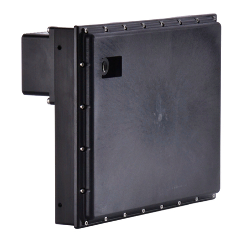
SWARCO CAIMAN-PRO Series User manual

SWARCO
CAIMAN-PRO
User Manual
CAIMAN-PRO
WIDE BEAM STOP+MOTIO
RADAR DETECTOR
CAIMAN-PRO_UserManual_BE_10

www.swarco.com
SWARCO TRAFFIC SYSTEMS GMBH, Niederkircher Straße 16, D-54294 Trier, Germany
T. +49-651-21002-0, +49-651-21002-999, E. detection@swarco.de
2/85
CONTENT
1Introduction.................................................................................................................................... 5
1.1 Abbreviations...........................................................................................................................5
1.2 Reference Documents.............................................................................................................5
2About the CAIMAN-PRO Radar Sensor....................................................................................... 6
2.1 Fields of Application ................................................................................................................6
2.2 Outstanding Features..............................................................................................................6
2.3 Principle of Operation..............................................................................................................7
2.3.1 Network operation............................................................................................................7
2.3.2 Flexibility of Radar Waveform..........................................................................................7
2.4 Tracked Object Interface.........................................................................................................7
2.5 Statistics Module V2 (SM2).....................................................................................................8
2.6 Event Trigger Module V2 (ETM2)............................................................................................9
2.7 Fail-Safe Capabilities.............................................................................................................10
2.8 Communication Interfaces.....................................................................................................10
2.8.1 Standard CAIMAN-PRO................................................................................................10
2.8.2 Relay Output Option......................................................................................................11
2.8.3 Wireless.........................................................................................................................11
2.9 Antenna overview..................................................................................................................12
2.10 Sensor Description and Hardware ID....................................................................................12
2.11 Coordinate System................................................................................................................13
2.12 Grounding Requirements ......................................................................................................14
2.13 Field Cable Specification.......................................................................................................14
2.13.1 Tested Field cables .......................................................................................................14
2.14 Accessories ...........................................................................................................................15
2.14.1 Brackets.........................................................................................................................15
2.14.2 Junction Box..................................................................................................................16
2.14.3 RS485 to USB Converter ..............................................................................................16
2.14.4 Other Accessories .........................................................................................................16
3Selecting the right CAIMAN-PRO Model and Sensor Location ..............................................17
3.1 Selecting the right antenna....................................................................................................17
3.1.1 Comparison low power vs. high power..........................................................................18
3.2 Select Area of Interest...........................................................................................................19
3.3 Verify the Radar Beam covers your Area of Interest.............................................................20
3.4 Vertical Installation Angle......................................................................................................21
3.5 Finding the optimal mounting position...................................................................................22
3.6 Standard Settings..................................................................................................................23
3.6.1 Type 80 Standard Setting..............................................................................................23
3.6.2 Type 32 Standard Setting..............................................................................................24
3.7 TMConfigurator Beam Simulation .........................................................................................25

www.swarco.com
SWARCO TRAFFIC SYSTEMS GMBH, Niederkircher Straße 16, D-54294 Trier, Germany
T. +49-651-21002-0, +49-651-21002-999, E. detection@swarco.de
3/85
4Getting Started.............................................................................................................................26
4.1 Quick Reference Guides .......................................................................................................26
4.2 TMConfigurator set-up software............................................................................................26
4.3 HOW TOs..............................................................................................................................26
5Data Communication...................................................................................................................27
5.1 Parameters............................................................................................................................27
5.1.1 TMConfigurator to send a Command............................................................................27
5.1.2 Basic Commands...........................................................................................................28
5.1.3 Special Commands .......................................................................................................29
5.2 Fail-Safe Capabilities.............................................................................................................29
6How to… .......................................................................................................................................30
6.1 How to use the Simulation-Modes.........................................................................................30
6.1.1 Simulation Mode 1: Targets and Objects ......................................................................30
6.1.2 Simulation Mode 4: Trigger Output Simulation..............................................................32
6.2 How to change the frequency band.......................................................................................33
6.3 How to read and change sensor parameters (experts only) .................................................35
6.3.1 Request Status..............................................................................................................36
6.4 How to export data to CSV format.........................................................................................36
6.5 How to use the polygon feature (experts only)......................................................................38
6.5.1 Configure Polygons .......................................................................................................38
6.5.2 Polygon settings ............................................................................................................40
6.5.3 Expert Options for “Limited” polygon .............................................................................41
7The TMConfigurator software ....................................................................................................42
7.1 TMConfigurator software installation and registration...........................................................42
7.2 Usage of the TMConfigurator software .................................................................................42
7.2.1 TMC window (former Easy Mode).................................................................................42
7.2.2 Create a new project .....................................................................................................43
7.3 Setup Process .......................................................................................................................44
7.3.1 Step 1: Find Intersection or Highway location...............................................................44
7.3.2 Step 2: Load Satellite Map ............................................................................................45
7.3.3 Step 3: Add a Sensor ....................................................................................................45
7.3.4 Step 4: Configure lanes, detection Zones and Stop bars..............................................46
7.3.5 Step 5: Assign Relays (Event Triggers) ........................................................................47
7.3.6 Step 6: Traffic Statistics.................................................................................................48
7.3.7 Step 7: Coverage Check ...............................................................................................49
7.3.8 Step 8a: Check communications...................................................................................50
7.3.9 Step 8b: Elevation and Roll ...........................................................................................51
7.3.10 Step 9: Guided alignment..............................................................................................52
7.4 Firmware Update...................................................................................................................53
8Frequency Approval....................................................................................................................54
8.1 Declaration of Conformity for Europe....................................................................................54
9Important Legal Disclaimer Notice ............................................................................................55

www.swarco.com
SWARCO TRAFFIC SYSTEMS GMBH, Niederkircher Straße 16, D-54294 Trier, Germany
T. +49-651-21002-0, +49-651-21002-999, E. detection@swarco.de
4/85
10 Appendix I: CAIMAN-PRO 32 Detector Data Sheet..............................................................56
10.1 User Safety Warning Information ..........................................................................................56
10.2 Sensor Data Sheet ................................................................................................................58
10.2.1 Sensor Photograph........................................................................................................58
10.3 Function Description..............................................................................................................59
10.4 Application Characteristics....................................................................................................61
10.4.1 Intersection Management..............................................................................................61
10.4.2 Arterial Management .....................................................................................................63
10.5 General Performance Data....................................................................................................65
10.5.1 Start-up time..................................................................................................................66
10.5.2 Self-Diagnose................................................................................................................66
10.5.3 Sensor Network.............................................................................................................66
10.5.4 Ethernet connection.......................................................................................................66
10.5.5 Compliance and Certifications.......................................................................................67
10.6 Sensor Dimensions ...............................................................................................................68
10.7 Connector..............................................................................................................................70
11 Appendix II: CAIMAN-PRO 80 Detector Data Sheet............................................................. 71
11.1 User Safety Warning Information ..........................................................................................71
11.2 Sensor Data Sheet ................................................................................................................73
11.2.1 Sensor Photograph........................................................................................................73
11.3 Function Description..............................................................................................................74
11.4 Application Characteristics....................................................................................................76
11.4.1 Intersection Management..............................................................................................76
11.4.2 Arterial Management .....................................................................................................78
11.5 General Performance Data....................................................................................................80
11.5.1 Start-up time..................................................................................................................81
11.5.2 Self-Diagnose................................................................................................................81
11.5.3 Sensor Network.............................................................................................................81
11.5.4 Ethernet connection.......................................................................................................81
11.5.5 Compliance and Certifications.......................................................................................82
11.6 Sensor Dimensions ...............................................................................................................83
11.7 Connector..............................................................................................................................85

www.swarco.com
SWARCO TRAFFIC SYSTEMS GMBH, Niederkircher Straße 16, D-54294 Trier, Germany
T. +49-651-21002-0, +49-651-21002-999, E. detection@swarco.de
5/85
1 Introduction
1.1 Abbreviations
CAN Controller Area Network
CSV Comma Separate Value
EIRP Equivalent Isotropically Radiated Power
ETM Event Trigger Module
GUI Graphical User Interface
PC Personal computer
SM Statistics Module
TBC To be confirmed
TBD To be defined
TMC Traffic Management Configurator
1.2 Reference Documents
Quick Guides
CAIMAN-PRO Installer Quick Reference Guide
CAIMAN-PRO SRO Quick Reference Guide
CAIMAN-Grounding-Recommendations
Descriptions and Manuals
CAIMAN-PRO-Bracket Description
CAIMAN-PRO-JunctionBox Description
CAIMAN-PRO-JunctionBox-Installation Manual
Data Sheets
CAIMAN / CAIMAN-PRO B
CAIMAN / CAIMAN-PRO M
CAIMAN / CAIMAN-PRO I
CAIMAN / CAIMAN-PRO T

www.swarco.com
SWARCO TRAFFIC SYSTEMS GMBH, Niederkircher Straße 16, D-54294 Trier, Germany
T. +49-651-21002-0, +49-651-21002-999, E. detection@swarco.de
6/85
2 About the CAIMAN-PRO Radar Sensor
2.1 Fields of Application
The CAIMAN-PRO sensor family can be used for many applications. Among those are:
Intersection Management
oStop Bar Detection
oCombined Stop Bar and Advance Detection
oAdvance Detection
oQueue Length Measurement
Arterial Management
oTraffic Counting and Classification
oWrong Way Vehicles detection
oIncident Detection
Note:
Please note that the Radar system –like any other sensor system –although being
well optimized and providing excellent performance, will not achieve a 100%
detection probability and will not achieve a false alarm rate equal to zero.
2.2 Outstanding Features
Truly Universal –serves a variety of applications
The most Advanced Tracking Radar
Lane Specific Detection
Individual Object Tracking
Flexible Installation
Statistics and Event Trigger Modules
Easy-to-use TMConfigurator Setup Software

www.swarco.com
SWARCO TRAFFIC SYSTEMS GMBH, Niederkircher Straße 16, D-54294 Trier, Germany
T. +49-651-21002-0, +49-651-21002-999, E. detection@swarco.de
7/85
2.3 Principle of Operation
Each individual CAIMAN-PRO sensor directly measures the following parameters of all moving
objects simultaneously in the field of view: (relative to the sensor)
Range
Radial Relative Speed
Azimut Angle
Those data are stabilized by tracking algorithms. Stopped objects are kept in the tracking
memory. The true vector of the relative speed is calculated. A data transformation into
Cartesian co-ordinates is performed. Those tracked and transformed data are transmitted over
the chosen communication interface.
The radar system will thus detect objects in the field of view of the sensor and cyclically report
the data ([x,y] position and relative speed vector) of those on an external interface. The
interface to the superior system (detector card, PC or the like) is a list of tracked objects
transmitted via RS485 or Ethernet
1
(or other) interface.
Each sensor comprises a RS485 interface for communication (standard interface) and an
Ethernet or CAN interface (deactivated by default).
2.3.1 Network operation
A sensor can be operated standalone or in a network of sensors.
2.3.2 Flexibility of Radar Waveform
The CAIMAN-PRO supports a variety of stand-alone or combined radar waveforms. The
operation mode can be determined by the radar firmware.
2.4 Tracked Object Interface
In a stationary application, usually the sensor output is a list of detected targets (reflectors) in
the sensor data output with the parameters
Range
Horizontal Angle (to determine the Position)
Vertical Angle (to determine the Height)
Radial Speed
Reflectivity level
Type of Target (Reliability Figure)
In addition to that, status and diagnose data from the sensor are reported.
The result of the tracking is an object list with the following parameters:
x position
y position
velocity magnitude and heading
2
size estimate or class estimate of the reflector
1
Ethernet will be made available in a future software update.
2
For compatibility reasons, an output of x speed and y speed is available as a option.

www.swarco.com
SWARCO TRAFFIC SYSTEMS GMBH, Niederkircher Straße 16, D-54294 Trier, Germany
T. +49-651-21002-0, +49-651-21002-999, E. detection@swarco.de
8/85
In any case, a visualization both of the targets and the objects is possible using the
TMConfigurator software in any PC equipped with a CAN, RS485 or Ethernet interface
3
.
For further information about the CAIMAN-PRO Sensor performance and communication
options refer to the further documentation.
2.5 Statistics Module V2 (SM2)
The Statistics Module is an Application based on the Tracked Object Interface. While the
Tracked Objects provide a high update rate of per vehicle data, the Statistics Module interprets
and accumulates those data to reduce the data amount transferred to the user and at user
selectable time intervals. The user can select to obtain the Statistics Data only.
The basic features provided are:
Lane specific report
Reports per measurement zone (32 measurement zones max.)
Report of Statistical Data
oVolume
oOccupancy
oAverage Speed
The extended features
4
provided are:
Reports per Vehicle class
Report of Statistical Data
o85 percentile speed
oHeadway
oGap
Capability to either polling or reporting activity
Figure 1 shows an example of the Statistics Module V2 output.
Figure 1:Statistics Module output example in TMConfigurator
3
Depending on interfaces offered by the CAIMAN PRO purchased. Check TMConfigurator system requirements.
4
Provided as a future software update

www.swarco.com
SWARCO TRAFFIC SYSTEMS GMBH, Niederkircher Straße 16, D-54294 Trier, Germany
T. +49-651-21002-0, +49-651-21002-999, E. detection@swarco.de
9/85
2.6 Event Trigger Module V2 (ETM2)
The Event Trigger Module V2 is an Application based on the Tracked Object Interface. With a
focus on events, the user can define and select from a variety of trigger conditions on zones.
Those triggers can be linked to Virtual Relays. Up to 64 Virtual Relays are supported per
sensor. The user can select to obtain output from the Virtual Relay States conditions only. The
output rate can be selected by the user.
Figure 2: Event Trigger Module example in TMConfigurator
The following features are provided:
Lane specific report
Reports per zone (32 zones max.)
Up to 64 Virtual Relays are triggered
Types of Trigger
oPresence
oSpeed
oEstimated Time of Arrival
5
oVehicle Class
6
oWrong Direction
oQueue Length
7
oCustom Trigger
Individual Delay and Extension of Trigger Signals
Figure 2 shows an example of the Event Trigger Module set-up and output.
5
In the United States, a one-time ETA is provided.
6
Provided as a future software update
7
Provided as a future software update

www.swarco.com
SWARCO TRAFFIC SYSTEMS GMBH, Niederkircher Straße 16, D-54294 Trier, Germany
T. +49-651-21002-0, +49-651-21002-999, E. detection@swarco.de
10/85
2.7 Fail-Safe Capabilities
This capability is planned for a future software update.
The sensor offers diagnostics for different classes of failures. They are named “Error
Diagnostic” conditions. It is clearly pointed out that not all possible failures can be detected by
the onboard diagnostics, and that the diagnostic features do not have 100%detectionrate and
/ or 0% false alarm rate.
The Error Detection triggers all assigned outputs both in communication protocol (and on
hardware, where SRO equipped). The Error Detection triggers by default
at critical sensor internal errors (detected by on-board diagnose) and
on detection of heavy rain.
It is possible to disable or adjust the Error Detection operation. Please refer to section 5.2.
2.8 Communication Interfaces
2.8.1 Standard CAIMAN-PRO
The Standard CAIMAN-PRO supports the following interfaces:
RS485 full-duplex, 115kbps (default, selectable)
CAN 2.0b (high-speed), 250kbps (default, selectable)
10/100 Mbps Ethernet (default, selectable)
8
Those interfaces can be accessed through the rear sensor connector. Please refer to the
CAIMAN-PRO sensor datasheets in the appendix for the pin-outs.
Figure 3: CAIMAN-PRO Traffic sensor –rear side
8
Interface is present on the hardware. Future software update will activate this functionality.

www.swarco.com
SWARCO TRAFFIC SYSTEMS GMBH, Niederkircher Straße 16, D-54294 Trier, Germany
T. +49-651-21002-0, +49-651-21002-999, E. detection@swarco.de
11/85
2.8.2 Relay Output Option
The Sensor Relay Option (RD_CaimanPRO_Relay) adds to the back of the standard
CAIMAN-PRO sensor. It can be ordered as a separate option to the CAIMAN-PRO sensor.
Eight contact pairs together with RS485 and Ethernet and CAN are provided by the SRO-
01xxxx. Furthermore, surge protection is offered on all signals.
For more details, please refer to the SRO Installer Quick Reference and to the Detector Data
Sheet.
Figure 4: RD_CaimanPRO_Relay module mounted to an CAIMAN-PRO Sensor (rear side)
2.8.3 Wireless
Several GSM and HSDPA modems have been tested and validated to work with the CAIMAN-
PRO sensor.
Among those are:
Airlink Raven XE (World)
9
Sierra Wireless LS300
10
Moxa OnCell G3151
Moxa OnCell G3150
Those devices are seamless integrated into SWARCO’s TMConfigurator setup tool (refer to
section 7 also).
9
Ethernet Input to that modem is required.
10
Ethernet Input to that modem is required.

www.swarco.com
SWARCO TRAFFIC SYSTEMS GMBH, Niederkircher Straße 16, D-54294 Trier, Germany
T. +49-651-21002-0, +49-651-21002-999, E. detection@swarco.de
12/85
2.9 Antenna overview
The table gives an overview for the latest antenna types and their preferred usage.
Table 2-1: CAIMAN-PRO Antenna overview
Type I80 / M80 / B80
Type I36 / M36 / B36
Applications
Stop Bar Detection
Stop Bar Detection
Advance Detection
Azimuth detection range
-40° to +40°
-18° to +18°
Azimuth measurement resolution
No resolution. Digital RX beam forming is used for beam
shaping and the resolution of simpler scenarios.
Elevation detection range
-12° to +12°
Number Antenna beams on receive:
(phase monopulse, fully overlapping)
Four RX antennas, phase monopulse principle. Digital RX
beam forming is applied.
Number Antenna beams on transmit:
(covering Field of View in total)
1, the full field of view given 4 lines above is illuminated.
Two way Azimut 3dB-beamwidth: xx°
-21° to +21°
-7° to +7°
Two way Elevation 3dB-beamwidth: xx°
-5° to +5°.
-5° to +5°
Sensitivity11 (typical) on
-Small car
-Truck
120m
250m
150m
320m
Dimensions (WxHxD):
Antenna size 97x79 mm plus housing
2.10 Sensor Description and Hardware ID
Every CAIMAN-PRO sensor housing is tagged with a type sticker containing the product
description and the serial number. It also contains a mark which side of the sensor is top.
Figure 5: Type sticker example
11
Assuming 20dBm EIRP output power.
Sensor model info
Sensor serial no.

www.swarco.com
SWARCO TRAFFIC SYSTEMS GMBH, Niederkircher Straße 16, D-54294 Trier, Germany
T. +49-651-21002-0, +49-651-21002-999, E. detection@swarco.de
13/85
For all standard housing versions, the cable outlet is on the rear side.
For special housing versions, when looking at the front of the sensor (radome), thecable outlet
is on the right side. It may be required that the sensor is mounted Bottom Up. In that case the
cable outlet is on the left side.
2.11 Coordinate System
The coordinate system of the CAIMAN-PRO sensor is illustrated in Figure 6 and Figure 7.
Origin
Variables:
rX–range in X-direction
rY–range in Y-direction
vX–speed in X-direction
vY–speed in Y-direction
|v| –speed magnitude
Ψ –heading
rr–range radial
vr–speed radial
–angle
X (rX, vX)
Y (rY, vY)
rr, vr
Ψ
|v|
Figure 6: Drawing of coordinate system
Figure 7: Angle sign in the coordinate system
Y
X
Negative angle
Positive angle

www.swarco.com
SWARCO TRAFFIC SYSTEMS GMBH, Niederkircher Straße 16, D-54294 Trier, Germany
T. +49-651-21002-0, +49-651-21002-999, E. detection@swarco.de
14/85
2.12 Grounding Requirements
The housing of the CAIMAN-PRO sensor is not electrically floated. It is connected to the
negative supply voltage instead. To assure correct operation of the sensor, please refer to
CAIMAN-Grounding-Recommendations for grounding instructions.
2.13 Field Cable Specification
The minimum cable requirements for an infield installation of the CAIMAN-PRO sensor are:
CAIMAN-PRO:
For use with Junction Box:
oOuter diameter 9 mm to 13 mm
oCable outlet for 6.5 mm to 9.5 mm also available
Power pair:
oAWG18 / cross section 1 mm² or better recommended
12
oFor all installations: the minimum voltage indicated in the data sheet has to be
granted for the operating unit
oFor NEMA cabinet installations: less than 14 V of voltage drop
Data pairs:
oTwisted pair (CAN 2.0b; RS485 full-duplex)
oTwo data pairs each as twisted pair (RS485 full-duplex; 10/100 Mbps Ethernet)
oZ = 100 Ohm to 120 Ohm @ 100 kHz / 1 MHz
oAWG24 / cross section 0.22 mm² or better
oLoop resistance better than 190 Ohm / 1000 m
Note:
SWARCO cannot provide a guarantee for cable types other than those verified by
SWARCO testing and advertised as such. The customer is required to verify by
testing the cable candidate for his particular purpose and installation variants, esp.
with regard to communication capabilities.
2.13.1 Tested Field cables
The following field cables have been verified by testing:
-Lapp UNITRONIC BUS YV COMBI IBS 3x2x0.22 , 3x1.0 ROHS
-Manufacturer part no. 2170217; Rated for direct burial / natural UV resistance.
-Tested distance 161m / 528ft.
-Lapp UNITRONIC LAN 1000 s/FTP Cat. 7 (L) PE 4x2xAWG 23/1
-Manufacturer part no. 2170198; Cat.7 cable; Rated for direct burial
-Tested distance 100m / 328ft.
-Olympic Wire 61530B Manufacturer part no. OLY 6150B
(https://www.olympicwire.com/)
-Tested distance up to 500ft. / 100+ installations.
-Tested by 3rd party using CAIMAN. SWARCO grants no guarantee for fit for purpose.
-Medikabel 9DB280431C01 (www.medikabel.de)
-UV rated cable for CAIMAN
12
For use with JBOX: conductor reduction at clamp on 0.5 mm² is requested

www.swarco.com
SWARCO TRAFFIC SYSTEMS GMBH, Niederkircher Straße 16, D-54294 Trier, Germany
T. +49-651-21002-0, +49-651-21002-999, E. detection@swarco.de
15/85
2.14 Accessories
The CAIMAN-PRO sensor is enriched by a set of accessories tomeet various customer needs.
A selection is briefly displayed below. For the most recent products, please visit
www.swarco.com.
2.14.1 Brackets
In order to mount and align the sensor the here described brackets can be used.
Standard Brackets (see Figure 8: BFW_Caiman_36S with sensor front Figure 8)
Standard brackets allow for adjustments of the elevation angle. They are designed for pole
mount, wall mount and tripod usage. Please refer also to the Bracket Description.
Advanced Brackets (see Figure 9)
Advanced brackets allow for adjustments of both the azimuth and elevation angle. They are
designed to further cover both horizontal and vertical bar mount as well as straight or angled
orientation. Please refer also to the Bracket Description.
Figure 8: BFW_Caiman_36S with sensor front
Figure 9: BFW_Caiman_36Awith sensor front, straight
orientation

www.swarco.com
SWARCO TRAFFIC SYSTEMS GMBH, Niederkircher Straße 16, D-54294 Trier, Germany
T. +49-651-21002-0, +49-651-21002-999, E. detection@swarco.de
16/85
2.14.2 Junction Box
The SWARCO Junction Box (RD_CaimanPRO_JB) offers a universal and easy to use field
installable way of connecting and surge protecting a CAIMAN-PRO sensor to the home run
cable. It can be easily added to the back of the standard CAIMAN-PRO.
Figure 10: RD_CaimanPRO_JB
2.14.3 RS485 to USB Converter
By means of the RS485 to USB converter, you can connect the CAIMAN-PRO sensor to a PC
easily and at low cost. For 24/7 installations, an industrial solution like Moxa Uport 1130I is
suggested.
Figure 11: RS485 USB converter –industrial solution: Moxa UPort 1130(I)
2.14.4 Other Accessories
Please find more accessories (and cables) for the Traffic Management CAIMAN-PRO on the
SWARCO website: www.swarco.com.

www.swarco.com
SWARCO TRAFFIC SYSTEMS GMBH, Niederkircher Straße 16, D-54294 Trier, Germany
T. +49-651-21002-0, +49-651-21002-999, E. detection@swarco.de
17/85
3 Selecting the right CAIMAN-PRO Model and Sensor
Location
Note:
Country dependent frequency regulations may require usage of the low power
version.
3.1 Selecting the right antenna
Select CAIMAN-PRO B32 / I32 / M32 if:
oThis is the default antenna
oFor large intersections (high distance to stop bar / extension)
oRoad is rather straight
o# of lanes monitored is 1-4, but verify coverage of all lanes + allowance
Select CAIMAN-PRO B80 / I80 / M80 if:
oIf type 32 cannot be applied
oDistance to stop bar is short
Figure 12: general characteristics of CAIMAN-PRO

www.swarco.com
SWARCO TRAFFIC SYSTEMS GMBH, Niederkircher Straße 16, D-54294 Trier, Germany
T. +49-651-21002-0, +49-651-21002-999, E. detection@swarco.de
18/85
3.1.1 Comparison low power vs. high power
Figure 13: Type 80 low power vs. high power
Figure 14: Type 32 low power vs. high power

www.swarco.com
SWARCO TRAFFIC SYSTEMS GMBH, Niederkircher Straße 16, D-54294 Trier, Germany
T. +49-651-21002-0, +49-651-21002-999, E. detection@swarco.de
19/85
3.2 Select Area of Interest
The following figure shows how Tracked Objects are built by the CAIMAN-PRO inside the
sensor beam.
Figure 15: Select Area of Interest
The planner / installer has to check the following steps:
Verify that there are 20+m (60ft) between max. range and area of interest
Verify the lanes are fully covered
Include some allowance at beam limits –example (B) is too tight
Verify the horizontal angle to road is within -20 deg .. +20 deg
Verify the horizontal angle to road is within -25 deg .. +25 deg
Verify the vertical angle to ground is within -3 .. +3 deg typical,
allowed are -9 .. +5 deg
(A)
(B)

www.swarco.com
SWARCO TRAFFIC SYSTEMS GMBH, Niederkircher Straße 16, D-54294 Trier, Germany
T. +49-651-21002-0, +49-651-21002-999, E. detection@swarco.de
20/85
3.3 Verify the Radar Beam covers your Area of Interest
The radar beam creates an oval shaped spot on the ground. The installer / planner has to
verify that the measurement point lies inside the covered area.
Please check these points:
Verify that there are 20m (60ft) covered by the beam between max. range and area of
interest (on all lanes)
Verify the lanes are fully covered by the beam; stop bar shall be fully covered by the
green beam.
Green beam shall not cover too much additional area right or left of stop bar. Use T45
if the stop bar area is small. Do not use CAIMAN-PRO 80 by default at every location.
Include some allowance at beam limits (on all lanes)
Recommended mounting parameters: see chapter 3.6.
Figure 16: Verify Radar Beam coverage
This manual suits for next models
9
Table of contents
Other SWARCO Security Sensor manuals
Popular Security Sensor manuals by other brands

aguilera electronica
aguilera electronica AE/C5-TV Installation guidelines

optrel
optrel weldCap quick start guide

Afriso EURO-INDEX
Afriso EURO-INDEX LAG-14 ER operating instructions

Bosch
Bosch ISN-AP1 installation instructions

Spectrex
Spectrex SharpEye 20/20R User and maintenance manual

Panasonic
Panasonic SF4B-F31G(V2) instruction manual

Niko
Niko 350-41750 Programming guide

PCB
PCB 2302-01A Installation and operating manual

Jula
Jula 400-235 operating instructions

Conrad Electronic
Conrad Electronic 182622 operating instructions

Honeywell
Honeywell Fire Sentry FS7-2173-2RP Installation guide and operating manual

Hytronik
Hytronik HIR23 quick start guide