CONTENTS
1. SPECIFICATIONS ...................................................................................... 1
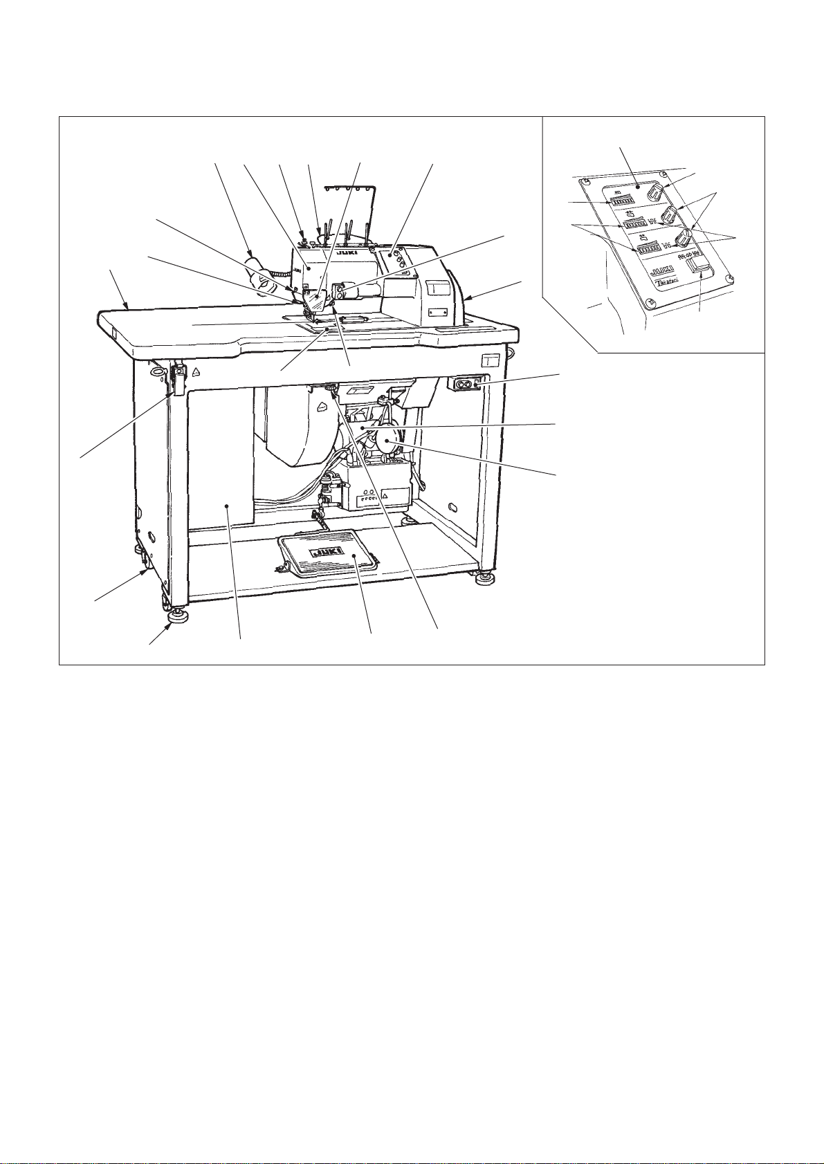
2. EXPLANATION OF UNITS......................................................................... 2
(1) Configuration .............................................................................................................2
(2) Operation panel (1Operation panel) .......................................................................3
3. EXPLANATION OF STITCH LENGTH COMPENSATION FUNCTION..... 5
(1) Function.....................................................................................................................5
1) In case the upper stitch becomes small...........................................................................................5
2) In case the upper stitch becomes large ...........................................................................................5
(2) Operation...................................................................................................................5
4. NEEDLE BAR CURVE AND TIMING ADJUSTMENT CHART ................. 6
5. STANDARD ADJUSTMENT ...................................................................... 8
(1) Before making the adjustments ................................................................................8
(2) Adjusting the home position (adjusting the graduation)............................................8
(3) Adjusting the needle bar groove cam and the left looper cam ...............................10
(4) Adjusting the needle bar.........................................................................................12
1) Adjusting the height of the support cylinder of the upper needle bar.............................................12
2) Adjusting the height of the support cylinder of the lower needle bar .............................................12
3) Adjusting the timing of transferring the needle ..............................................................................14
4) Centering the needle bar ...............................................................................................................14
(5) Adjusting the needle guide claw .............................................................................16
1) Adjusting the needle and the needle guide claw ...........................................................................16
2) Adjusting the thread tension of the needle guide claw ..................................................................16
3) Adjusting the timing of opening/closing the tubular cam of the needle guide claw........................18
(6) Adjusting the thread path guide..............................................................................18
(7) Adjusting the thread haul lever ...............................................................................20
1) Cam timing.....................................................................................................................................20
2) Adjusting the thread haul lever ......................................................................................................20
(8) Adjusting the brush cam .........................................................................................22
(9) Adjusting the hook finger ........................................................................................22
1)Adjusting the movement amount of the hook finger .......................................................................22
2) Adjusting the rotating shaft and the tension spring........................................................................24
3) Adjusting the clearance between the hook finger and the needle .................................................24
(10) Adjusting the hook finger to release the thread tension .......................................26
(11) Adjusting the eccentric amount of the eccentric pin .............................................26
(12) Adjusting the lower feed .......................................................................................28
1) Adjusting the feed eccentric boss and the lifting cam....................................................................28
2) Adjusting the height of the lower feed dog and the throat plate.....................................................28
(13) Adjusting the upper feed dog and the lower feed dog ..........................................30
(14) Adjusting the presser foot.....................................................................................30
(15) Adjusting the upper feed eccentric shaft ..............................................................32