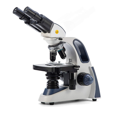
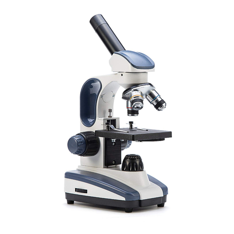
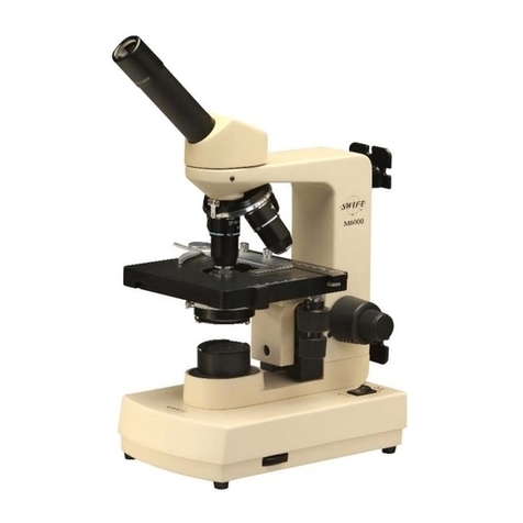
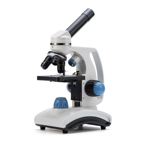
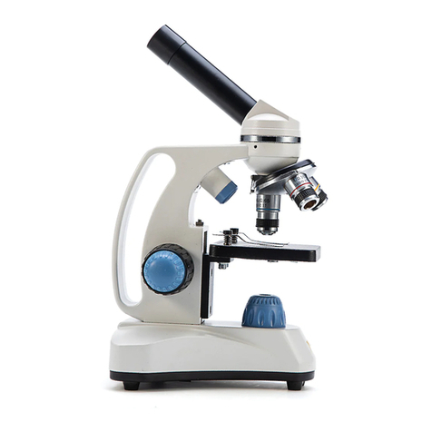
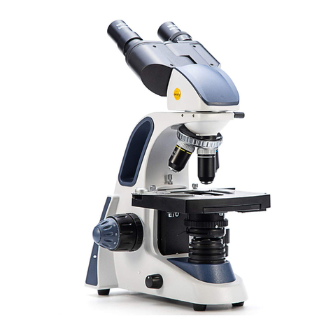
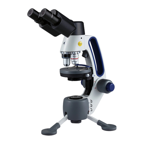
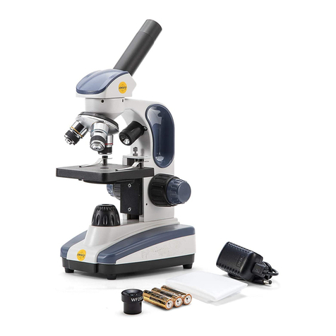
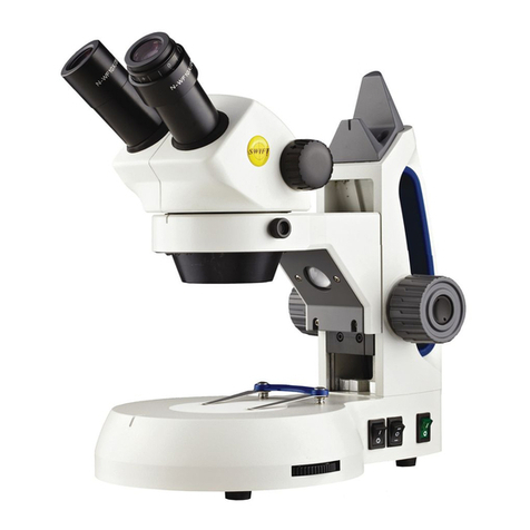
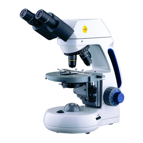
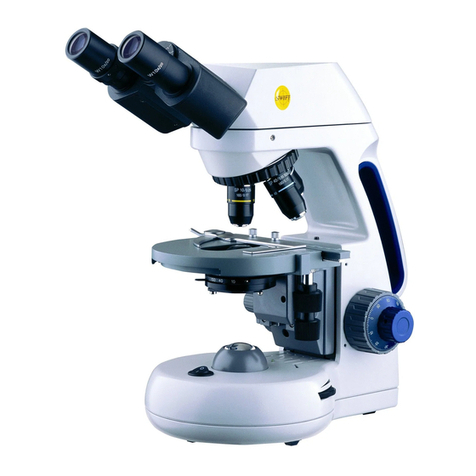
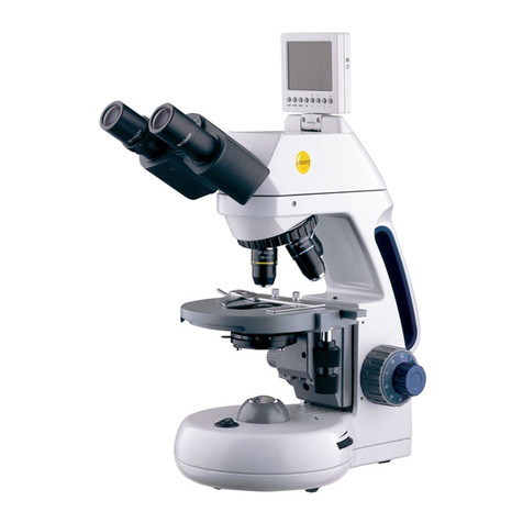
Swift M10L Series User manual


1
SWIFT M10L SERIES
Your Swift M10L microscope is an instrument of precision, both
optically and mechanically, that is designed to last a lifetime with a
minimum amount of maintenance. It is built to the highest and
most rigid optical and mechanical standards and has many built-in
features to ensure durability and high performance in the hands of
both student and professional users. The Swift M10L Series
combines traditional microscopy with advanced technology. This
microscope is equipped with superior optics offering bright clarity
and crisp resolution, a built-in 5 Megapixel digital camera for
capturing still images or streaming video, an internal SD card
reader/writer to save captured images, and a built-in 3” LCD screen
for shared viewing. The M10L also provides USB and Mini AV plug
outputs for direct connection to a computer, TV monitor or
video/LCD projectors.
2
Nosepiece
Swift M10L Series
Illuminator
Objective
Slide Holder
Finger Lever
Head LCD Screen
E
y
e
p
iece
On/Off Switch
Illuminator Rheostat
Iris Diaphragm
Mechanical
Stage Control
Coarse Focus
Control
Diopter
Adjustment
Fine Focus
Control
A/C Adapter
Power Port
Power Button
USB Port
Analo
g
Out
p
ut

3
COMPONENTS OF THE MICROSCOPE
ARM – the vertical column (attached to the base) which supports the
stage, and contains the coarse and fine adjusting knobs and
mechanism.
BASE – the platform of the instrument to which the arm is attached.
The base stands on rubber feet and contains the illuminator
assembly
COARSE FOCUS – the larger, outer knob of the focus control which
facilitates rapid and heavy movement of the focusing mechanism. In
order to prevent gear damage, the focus control is equipped with
an upper limit stop that protects the high magnification objectives
and slides.
COAXIAL CONTROLS – the focusing control mechanism moves the
stage up and down to bring the specimen into focus. A coaxial focus
control combines the coarse and fine focus mechanisms into one
control with inner and outer knobs, which are located on both sides
of the arm. This coaxial focus control incorporates a clutch
mechanism which allows for slippage at the extreme ends of the
focus range to prevent damage to the gears.
CONDENSER – the function of the condenser is to provide full
illumination to the specimen plane and to enhance the resolution
and contrast of the object being viewed. The standard condenser of
the M10L Series has a Numerical Aperture of 1.25 with filter carrier
and iris diaphragm. It is mounted in a sub–stage focusing assembly
that can be raised or lowered for precise light control.
DIOPTER ADJUSTMENT – designed to help compensate for the
difference between the user’s eyes and is located on the left
eyepiece of the binocular head
EYEPIECES – the upper optical element that further magnifies the
primary image of the specimen and brings the light rays in focus at
the eyepoint.
FINE FOCUS – the smaller inner knobs of the focus control which
allows for slow and subtle focusing movement to bring the specimen
into sharp focus.
HEAD – the upper portion of the microscope which contains the
refracting prisms and the eyepiece tubes which hold the eyepieces.
4
ILLUMINATION – the M10L Series uses a variable intensity 3 watt
Light Emitting Diode (LED).
IRIS DIAPHRAGM – a multi-leaf round shaped device which is
controlled by a lever. It is similar to a camera shutter, and is
installed under the condenser. By moving the lever back and forth,
the iris diaphragm opens and closes, increasing and decreasing the
contrast of the specimen. If the image is “washed out” the iris
diaphragm is opened too wide. If the image is too dark the iris is not
open wide enough.
MONOCULAR – a microscope head with a single eyetube and
eyepiece.
NOSEPIECE – the revolving turret that holds the objective lenses,
permitting changes in magnification by rotating different powered
objective lenses into the optical path. The nosepiece must “click”
into place for the objectives to be in proper alignment.
OBJECTIVES – the optical systems which magnify the primary image
of the instrument. Magnifications are typically 4X, 10X, 40X and
100X
SEIDENTOPF – a binocular head design where the interpupillary
adjustment (increasing or decreasing the distance between the
eyepieces) is achieved by twisting the eyepiece tubes in an up and
down arc motion similar to binoculars.
STAGE – the table of the microscope where the slide is placed for
viewing. This component moves upward and downward when the
focusing knobs are turned. The stage of the M10L has a built-in
mechanical stage with a below-stage ergonomic “X” and “Y” axis
controls. A finger clip holds the slide securely and is designed to
provide a slow return to provide protection to the specimen.
IMPORTANT TERMINOLOGY
DEPTH OF FOCUS - the ability of a lens to furnish a distinct image
above and below the focal plane. Depth of focus decreases with the
increase of numerical aperture or with the increase of
magnification.
5
DIN – (Deutsche Industrial Normen originally Deutsches Institut für
Normung). A German standard for the manufacturing of microscope
lenses.
EYE POINT or EYE RELIEF – the distance from the eye lens of the
eyepiece to your eye where a full field of view is seen.
FIELD OF VIEW - the area of the object that is seen when the image
is observed. It may range in diameter from several millimeters to
less than 0.1mm.
FOCAL LENGTH - parallel rays of light after refraction through a
lens will be brought to a focus at the focal point. The distance from
the optical center of the lens to the focal point is the focal length.
NUMERICAL APERTURE (NA) – a measure of an objective’s light
gathering capabilities. The concept may be compared to the F-stop
in photographic lenses. Generally speaking, N.A. values of less than
1.00 are "Dry" objectives. Values of 1.00 or greater require oil as a
medium. Please note that condensers are part of the optical system
and are also assigned an N.A. value. That value must be at least as
high as that of the highest objective used.
PARFOCAL – a term applied to objectives and eyepieces when
practically no change in focus is needed when changing objectives.
The objectives on your microscope are parfocalized at the factory
so that only a slight adjustment of the fine focus knob is needed to
maintain focus when switching magnification.
RESOLUTION or RESOLVING POWER – the ability of a lens to define
the details of the specimen at a maximum magnification. This is
governed by the NA (Numerical Aperture) of the lens. For example,
a 40X objective with NA 0.65 has a maximum resolving power of
650X, equal to 1000 times the NA. This rule of NA x 1000 is true of
all achromatic objectives.
WORKING DISTANCE – the distance from the lens of the objective to
the cover slip on the slide, when the specimen is in focus.
USING THE SWIFT M10L SERIES MICROSCOPE
Once you have learned the terminology and purpose of each
component of the microscope, use of the microscope is simple. By
6
following these steps, you will be able to begin studying specimens
quickly and easily.
1. Open the slide holder of the mechanical stage by pressing the
slide holder finger lever, and carefully place the slide against
the fixed side and back edge of the mechanical stage. Now
slowly release the slide holder finger lever allowing the “finger”
to hold the slide in place.
2. Align the specimen under the objective lens by using the
adjustment knobs under the mechanical stage. The bottom knob
moves the slide from right/left while the top knob adjusts the
slide from front/back. These knobs allow for precise movement
and scanning of the slide.
3. Rotate the nosepiece to place the lowest power objective (4XD)
over the specimen. Be sure the objective “clicks” into position.
(If you do not have a Swift M10L with Binocular Head please omit
step 4-5.)
4. Adjust the interpupillary distance of the Seidentopf binocular
head for a comfortable view. Adjust the eyepiece tubes of the
binocular head by moving the eyepiece tubes in an arc motion
to the position where one perfect circle can be seen in the field
of view.
5. For increased viewing comfort when using the Binocular Head,
use the left eye diopter adjustment to compensate for the
differences between the user’s eyes. Set the adjustable left eye
diopter at zero. Close your left eye and focus with your right
eye only by using the coaxial focusing knobs. Now using your
left eye only (close your right eye), adjust the diopter ring until
a clear image is seen. Now the binocular head is set for you to
observe the specimen.
6. While viewing through the eyepiece, rotate the coarse focus
knob to bring the specimen into focus. This should be done
slowly and carefully.
7. To adjust the contrast of the specimen, open the iris diaphragm
to its largest aperture. If additional contrast is required to
permit accurate viewing of the specimen, the diaphragm should
be slowly closed until the details of the specimen are sharply
defined. Be careful not to close the aperture too much, as you
may be achieving a higher contrast, but the fine structure of the
image may be destroyed. Reducing the aperture increases the
contrast and depth of focus, but it also reduces resolution and

7
introduces diffraction. The aperture must be adjusted for each
objective.
8. Next, use the fine focus control to refine the focus and provide
the sharpest image.
9. Now you can rotate the nosepiece to higher magnification
objectives. The objectives are parfocalized, meaning that once
the lowest objective (4XD) is focused, only a slight turn of the
fine focusing knob is required when changing to the 10XD,
40XRD and 100XRD objectives.
OIL IMMERSION
It is desirable to use immersion oil with the 100XRD objective. Oil
generates a fine resolution and brightens the image viewed through
the microscope. Place a tiny amount of oil (1 very small drop) onto
the slide (between the slide and the objective tip) prior to focusing
with the 100XRD objective. It is essential to thoroughly clean the
objective tip after use. Please contact Swift Optical or your
authorized Swift dealer for the appropriate immersion oil to use.
IMPORTANT: The working distances from the 100XRD and 40XRD
objectives to the slide surface are very close. Even though the
objectives are sealed to prevent oil contamination, it is a good
practice to avoid dragging these objectives through an oiled slide.
PHASE CONTRAST
The phase contrast microscope reveals fine detail in transparent
objects which possess very little contrast. Unstained living
organisms and cells can be studied without danger of artifacts
produced by killing, fixing or staining reagents. The M10L can be
outfitted with a multi-phase system (MA10050) that includes a set of
Plan Phase objectives and a special phase condenser carousel.
Please refer to the detailed instruction sheet enclosed with each
phase kit for proper use.
Immersion Oil
100XRD Objective
Slide
8
DIGITAL HEAD SPECIFICATIONS
Still Image Resolution- 5 MP Real/12 MP Interpolated
Memory- 8 MB Internal/ Up to 2 GB SD Card through expansion slot
(not supplied)
Video Out- Analog to RCA with supplied cable (480 lines of
resolution)
Battery- NP-40, 3.7V, 550 mAh, LI-ION. Built-in battery lasts up to 2
hours on continuous use with full charge
Digital Out- Through USB 2.0 to Swift Software at 640 x 480
Screen- Flip up 3’ TFT Screen
Optical Head- Binocular with WF10X 20mm Eyepieces or Monocular
with WF10X 18mm Eyepiece
LCD SCREEN
To use the built in LCD Screen, lift the screen back to bring the
screen into the viewing position. The screen can also be slightly
rotated right or left for easier viewing between multiple users.
Please use caution when rotating the screen. It is not designed to
be rotated 360 degrees.
An A/C adapter has been included with the microscope to provide
constant power to the LCD screen and camera. The 4.2 volt A/C
adapter power port is located on the right side of the LCD screen
housing below the power button.
PLEASE NOTE: The LCD screen and camera can also be operated for
approximately 2 hours by using the built-in rechargeable battery.
The battery life icon is shown in the upper left corner of the LCD
screen. (Please see battery charging section)

9
LCD SCREEN BUTTON FUNCTIONS
1. The SNAP button captures an image in the still image mode or
starts/stops the capturing of a movie in video mode.
2. The MODE button will scroll through the three camera modes
shown on the LCD screen (Still Image/Video/Playback).
3. The MENU button displays the setting choices for each of the
three modes. Once inside the menu, you will notice two tabs.
The selected tab will show a blue background. Each tab has
several choices beneath it. You can switch back and forth
between the two tabs by pressing the LEFT and RIGHT arrow
buttons.
4. The ZOOM/UP button is used to zoom in while viewing a live or
saved image. It can also be used to scroll up when viewing a
zoomed image or navigate through menu options.
5. The LEFT button is used to navigate through a menu, cycle
through saved images, scroll left when viewing a zoomed image
and to exit a menu.
6. The OK button is used to confirm an action within the menu or
to switch from zoom to scroll when viewing a zoomed image.
7. The RIGHT button is used to navigate to the right in a menu. It
can also remove icons from view on the LCD Screen, switch off
the LCD screen, scroll right when viewing a zoomed image and
cycle through saved images. 10
8. The ZOOM/DOWN button can be used to zoom out while
viewing a live or saved image. It can also be used to scroll
down when viewing a zoomed image or navigate through menu
options.
9. The POWER button can be used to turn the LCD screen and
camera on and off.
OPERATING THE BUILT-IN CAMERA
1. Press the POWER button (9) on the right side of the LCD screen
to turn the camera on. A Swift logo will briefly appear on the
screen.
2. The camera will start in the default still image capture mode.
Bring the specimen into focus and capture an image by pressing
the SNAP button (1).
3. Press the MODE button (2) to cycle through the various camera
modes:
A. Image capture
B. Video capture
C. Playback
The icons shown above will be displayed in the upper right corner
of the LCD Screen.
IMAGE CAPTURE MODE
This mode allows you to capture images and save them to the
internal memory or an SD Card. When you are using the camera in
image capture mode, you can use the zoom keys to zoom in
(ZOOM/UP(4)) and zoom out (ZOOM/DOWN(8)) on the live image.
You can click the RIGHT(7) button to hide the on-screen icons.
Press RIGHT(7) again and the display will turn off. Note that in this
mode, the camera is still operational and by pressing SNAP(1) an
image can still be captured.
The blue numbers in the lower right corner of the LCD screen
indicate how many still images can be captured and saved to
memory with the current image size and quality settings. Image
quality (indicated by stars), picture size (indicated by white

11
number) icons are also displayed on the LCD screen as a quick
reference, but will not appear on a captured image.
VIDEO CAPTURE MODE
This mode allows you to capture a video of what you see on the LCD
screen. For instance: If you move the stage controls after starting
the video mode, any movement will be seen on the LCD Screen.
In video capture mode, the ZOOM buttons (4 & 8) allow you to zoom
in and out of the image displayed on the LCD Screen. You can click
the RIGHT button (7) to hide the video icon. Clicking the right
button a second time will blank out the LCD Screen. Please note
that the camera is still operational and by pressing SNAP (1) a video
can still be recorded. The remaining length of video that can be
saved to memory and the video setting information is displayed in
the lower right corner of the LCD screen, but will not appear on the
captured video.
PLAYBACK MODE
“No image” will be displayed on the playback mode until an image
or video is captured to internal memory or an SD Card is inserted
and images are captured.
In the playback mode, you can scroll through the images and video
files you have captured by using the LEFT and RIGHT buttons. Click
on the ZOOM/UP button(4) to play or pause a video file. Pressing
the OK button(6) during playback will increase the speed of the
playback (1x, 2x, 4x, and 8x speed). Pressing the LEFT button
during playback will play the video backwards and pressing the
RIGHT button will resume playing the video forwards. If you are
viewing a saved still image, you can use the zoom keys to zoom in
(ZOOM/UP(4)) and out (ZOOM/DOWN(8)) on the captured image. If
you zoom in (ZOOM/UP(4)), you can press the OK button(6) and use
the Arrow keys (4,5,7 and 8) to navigate around the image. Press
the OK button (6) again and zoom out of the image
(ZOOM/DOWN(8)) to return to the normal view.
A counter in the lower right corner of the LCD screen will display
the order in which images or videos have been captured. The
counter will increase as more images and videos are captured.
MENU FUNCTIONS
12
To access the camera’s setting menu, press the MENU button(3).
Inside the menu for each of the three modes, you can manually set
certain camera parameters such as the ISO, color, white balance,
saturation, and sharpness as well as other camera functions. We
suggest that you change these functions only when you are familiar
with the basic operation of the camera.
Each menu has two tabs with options. The image capture, video
capture, and playback modes have a unique tab. The setup tab in
each of the three modes will have the same options. You can move
between the two tabs by pressing the RIGHT (7) and LEFT (5)
buttons. To navigate up or down in a menu, use the UP (4) or DOWN
buttons (8). To select an option in a menu press OK (6). Once a
choice is selected, press the LEFT (5) button to leave that screen.
Depending where you are in a menu, you may need to press the
LEFT button (5) up to three times to totally leave the menu screen
HELPFUL HINT: If you get into the menus and get lost and are
unsure how to proceed, pressing the MODE button will let you
escape.
The image capture, video capture, playback and setup menus are
documented on the next page:

13
STILL IMAGE CAPTURE MENU
Setting Default Options
12M 3M
Size 5M 8M 2M
5M 1.3M
Fine
Qualit
y
Fine Standard
Econom
y
Auto Portrait
Scene
Mode Auto Sport Landscape
Night Backlight
2
1
0
-1 -2
EV 0 1
2/3 2/3 - 1/3
-1 1/3
1
1/3 1/3 - 2/3
-1 2/3
Auto Tungsten
White
Balance Auto Daylight Cloud
y
Balance Fluorescent
Auto
ISO Auto 100
200
Standard
Colo
r
Standard Vivid
Sepia
Monochrome
High
Saturation Normal Normal
Lo
w
High
Sharpness Normal Normal
Lo
w
Off
Time
Stamp Off Date Only
Date & Time
14
SIZE – Selects the megapixel size of still images. The M10’s built-in
camera has a maximum true resolution of 5 megapixels. The pixels
of still images taken with the size setting above 5 megapixels will be
interpolated (software will add pixels to the image to simulate a
higher resolution).
QUALITY – Adjusts the quality of the images. The FINE setting will
offer the best image quality, but will require more memory. The
ECONOMY setting will require the lowest amount of memory, but
the image may lose some clarity. The STANDARD is a compromise
between image quality and required memory space.
SCENE MODE – Changes the camera’s capture settings to preset
values that best suit the type of subject that is being captured. For
most microscopy purposes it is best to leave this setting on AUTO.
Users capturing pictures of moving objects may use SPORT mode or
phase contrast users may use MONOCHROME mode with improved
results.
EV (exposure value) – represents the combination of aperture,
shutter speed, and camera sensitivity. In AUTOMATIC mode, the
camera will determine the optimal combination of aperture, shutter
speed, and sensitivity for the best image.
WHITE BALANCE - Adjusts the white balance settings to the optimal
setting for different shooting conditions. The AUTO setting is
recommended.
ISO – Adjusts the shutter speed settings. AUTO is the preferred
setting for most circumstances. The ISO setting can be manually
increased to raise the shutter speed which reduces the potential for
capturing blurred moving objects.
COLOR – The STANDARD setting captures colors normally. The VIVID
setting emphasizes the contrast and color saturations to capture
bold colors. The SEPIA setting captures in sepia tones. The
MONOCHROME setting remaps colors so they fall within shades of a
single color.
SATURATION – Adjusts the intensity of the color in an image.
NORMAL is the default setting. The HIGH setting will artificially
intensify color and the LOW setting will add a gray scale affect to
the image.
SHARPNESS – Adjusts the clarity of details in a captured image.
NORMAL is the default setting, but improved results may be
achieved by trying different settings for a particular specimen.

15
TIME STAMP – The default setting is set to OFF. If desired, a date or
date and time setting can be selected to display information on the
LCD screen and captured image.
VIDEO CAPTURE MENU
Setting Default Options
Size VG
A
VG
A
QVG
A
EV +0.0 Selectable from -2 TO
+2
White Balance Auto Auto
Daylight
Cloud
y
Tungsten
Fluorescent
SIZE – Selects the pixel size of the video output. VGA for 640 x 480
or QVGA for 320 x 240
EV – (exposure value) – represents the combination of aperture,
shutter speed, and camera sensitivity. The EV can be adjusted from
-2 to +2.
WHITE BALANCE – Adjusts the white balance settings to the optimal
setting for different shooting conditions. The AUTO setting is
recommended.
16
PLAYBACK MENU
Setting Default
Options
Delete Next
Menu Single
All
Select
Copy To
Card
Slide Sho
w
3 Sec.
3 Sec.
5 Sec.
10 Sec.
DPOF Next
Menu Single
All
Protect Next
Menu Single
All
Select
Thumbnail Execute
Volume 8
Selectable
1-8
DELETE – Options to remove single or all captured images from
memory.
COPY TO CARD – Copies all images stored in the microscope’s
internal memory to a removable SD card.
SLIDE SHOW – Selects the length of time a picture is displayed
during a slide show before it is replaced by another image.
DPOF - (Function disabled)
PROTECT – Adds or remove file protection to images to help prevent
accidental deletion.
THUMBNAIL – Displays reduced size versions of saved images for
quicker navigation through stored images.
VOLUME - (Function disabled)

17
SETUP MENU (ALL THREE MODES)
Setting Default Options
Format Next
Menu Cancel
Execute
Beep On On
Off
Language English English French
German Italian
Spanish Portuguese
Chinese
Auto Off 3 Min 1 Min 3 Min
5 Min Off
Sys. Reset Next
Menu Cancel
Execute
Light Freq. 60 Hz 60Hz
50Hz
TV Out NTSC NTSC
PAL
Date Input Next
Menu Off
Set
USB PC Cam PC Cam
Disk Drive
FORMAT – Select this option to reformat the internal or SD card
memory and erase all of the saved data.
BEEP – (Function disabled)
LANGUAGE – Used to change the default ENGLISH setting to display
menu information in another language.
AUTO OFF – Used to automatically turn the LCD screen off after a
preset amount of time to conserve battery power. The default
setting is 3 minutes, but can be set to OFF to disable this feature.
18
SYSTEM RESET – Used to reset all the settings to the factory default
setting.
LIGHT FREQUENCY – This setting should be set to 60HZ for users in
the United States.
TV OUTPUT – Used to select the proper regional video output. The
NTSC setting should be selected for users in the United States.
DATE INPUT – Used to select the format of the date being displayed
and to set the time and date.
USB – Used to change the way a computer detects and recognizes
the M10’s hardware when connected via the USB cable. The M10’s
internal memory will be detected as a flash drive when the DISK
DRIVE setting is selected. To use the M10’s camera with the
Swiftcam II software the PC CAM setting must be selected. The
PRINTER setting is disabled and will not function.
USING THE CAMERA WITH AN ANALOG IMAGING DEVICE
The analog cable that was included with the microscope can be used
to connect the camera to a device that accepts an RCA video input.
Simply plug the Mini A/V plug end of the cable into the left side of
the microscope’s LCD housing and the other end to an available RCA
input on the analog imaging device. Make sure the correct video
input mode is selected on the imaging device. The microscope’s
LCD screen will not display a live image while the RCA cable is
connected to the microscope’s camera.
* In order to ensure that the correct format is displayed, do the
following: Click on Menu (3), then click on the Right (7) button to
access the setup menu. Scroll down using the Down button (8) to
ensure the light frequency is set to 60HZ and the TV Output is set to
NTSC.
USING THE CAMERA WITH A COMPUTER
The microscope’s LCD screen will not display a live image while
the USB cord is connected to the microscope’s camera. Power to
the camera will be provided by the computer’s USB port so it is
not necessary to have the A/C adapter plugged in at the same
time.

19
Detailed instructions on how to install and use the software is
included on the Swiftcam Imaging II software CD. The instructions
shown below will give users the basic steps to getting started
with using the camera with a computer.
The Swiftcam II Imaging software must first be installed on a
computer before a live camera image can be viewed on a computer.
The minimum computer requirements to use the camera is having
an available USB 2.0 port, 512MB of RAM, 1GHz CPU, 500MB free HD
space and either Windows XP or Vista on the computer.
1. Press the power button on the right side of the LCD screen
housing to turn on the LCD screen and camera.
2. Insert the mini USB end of the cable that was supplied with
the microscope into the mini USB port on the left side of the
LCD screen housing. Connect the other end of the USB cable
to an available USB 2.0 port on a PC computer. The video
signal that was being sent to the LCD screen will now be
sent through the USB cable instead.
3. Install the Swiftcam II Imaging software on the PC computer
you will be using with the microscope. The software should
automatically detect and install the correct “Swift DV
Camera” driver.
IMPORTANT: The next time you connect the M10 to a
computer, make sure the USB cable is connected to the
same USB port that was used during initial installation or
the software driver will have to be re-installed).
4. After the software is installed, start the Swiftcam II Imaging
program and click on the CAPTURE (camera) icon to view a
live image.
5. The background balance setting will need to be adjusted to
compensate for any uneven illumination light patterns.
Place a slide on the stage. Use the mechanical stage
controls to move the specimen out of the field of view so an
empty/blank spot of the slide is being displayed. Click on
the “Background Balance” adjustment box found on the
bottom of the basic setting toolbar to smooth out the light
pattern.
6. Use the mechanical stage controls to bring the specimen
into the field of view and use the microscope’s focusing
controls to bring the specimen into focus.
7. Use the mouse pointer and hold the left mouse button while
dragging the mouse to create a small box in an area of the
image that should be displayed as a white color. (The size of
20
the box does not make a difference as long as it is only in an
area that should be displayed as white). Click on the “White
Balance” adjustment box found on the toolbar.
8. Click on the camera icon in the upper left corner of the
screen to switch to the “Capture” toolbar. An image can be
captured by clicking on the “Capture” box. A video clip can
be recorded by clicking the “Record” box.
9. Captured Images and video clips can be viewed by selecting
the “Swiftcam Imaging II” window found on the windows
toolbar at the bottom of the computer screen.
ACCESSING THE INTERNAL MEMORY
The microscope’s USB output is set to be detected by a computer as
a camera device by default. The USB output setting can be changed
to allow a computer access to the microscope’s internal memory to
transfer saved images.
To change the USB setting to hard drive mode:
Click on MENU (3), then click on RIGHT button (7) to access the
Setup mode. Scroll down with the DOWN button (8) to view the USB
setting. Click OK button to access to the USB choices. Scroll to the
Disk Drive setting and press OK to select it. Press the LEFT button
twice to exit the menu.
Insert the mini USB end of the cable that was supplied with the
microscope into the mini USB port on the left side of the LCD screen
housing. Connect the other end of the USB cable to an available USB
2.0 port on a PC computer. The computer will detect the
microscope’s internal memory as an external storage device which
can be accessed from the computer’s “My Computer” window.
SD CARD
Please ensure the camera is OFF before inserting or removing the
SD card.
The M10’s digital head has a built-in memory of 8MB. The SD Card
Expansion Slot, found on top of the LCD screen housing, can be used
to increase the amount of images that can be saved. The SD Card
Expansion Slot is compatible with SD cards up to 2GB of memory.

21
The SD Card must be inserted into the slot in the orientation shown.
Notice the orientation of the notch on the SD Card. It must match
the picture shown above the slot on the LCD Screen. When the card
is properly inserted in the top of the LCD Screen it will click into
place and lock. To remove the card, push down gently on the top of
the SD Card and it will unlock and can be removed.
BATTERY CHARGING
The internal rechargeable battery can be used to power the LCD
screen and camera. It can be charged by using the 4.2 volt A/C
adapter included with the microscope or by connecting it to a
computer via the USB cable. The A/C adapter can charge the
battery while the screen is powered on or off. When using a
computer’s USB port to charge the battery, the LCD screen must be
turned off before the USB cable is connected. The LED indicator
above the USB connection on the side on the LCD screen housing will
be green if the battery is charging properly via USB. The LCD and
camera will run for approximately 2 hours after a 2 1/2 hour charge.
CARE AND CLEANING
CLEANING – the front lens of the objectives (particularly the 40XRD
and 100XRD) should be cleaned after use. First, brush with a soft,
camel hair brush or blow off with air pressure from a rubber syringe
to remove dust particles. Then, wipe gently with a soft lens tissue
moistened with lens cleaning solution or distilled water, and dry
immediately with a clean lens paper.
CAUTION - Objectives should never be disassembled by the user.
If repairs or internal cleaning should be necessary, this should
only be done by qualified, authorized Swift microscope repair
technician.
The eyepiece(s) may be cleaned in the same manner as the
objectives, except in most cases, lens cleaning solution will not be
required. In most instances breathing on the eyepiece to moisten
22
the lens and wiping dry with a clean lens tissue is sufficient to clean
the surface.
Lenses should never be wiped while dry as this will surely scratch or
otherwise mar the surface of the glass.
The finish of the microscope is hard epoxy and is resistant to acids
and reagents. Clean this surface with a damp cloth and mild
detergent.
Periodically, the microscope should be disassembled, cleaned and
lubricated. This should be done only by a qualified, authorized
Swift microscope repair technician.
DUST COVER AND STORAGE – All microscopes should be protected
from dust by a dust cover when not in use or in storage. A dust
cover is the most cost-effective microscope insurance you can buy.
Ensure that the storage space is tall enough to allow the microscope
to be placed into the cabinet or onto a shelf without making undue
contact with the eyepieces. Never store microscopes in cabinets
containing chemicals, which may corrode your microscope. Also, be
sure that the objectives are placed in the lowest possible position
and the rotating head is turned inward and not protruding from the
base. Microscopes with mechanical stages should be adjusted
toward the center of the stage to prevent the moveable arms of the
mechanical stage from being damaged during storage in the cabinet.
LED REPLACEMENT
The Swift M10L is equipped with a 3 watt LED illumination system.
The life of the LED may vary depending on use and intensity. To
prolong the life of the LED, you should always turn off the unit when
not in use.
It is important that you only use a Swift replacement LED because it
is integrated onto a circuit board. This LED has been tested and
approved for life span, color temperature and brightness. Please
call the Swift Optical Parts Department at (877) 967-9438 for
replacement parts information.
Make sure the microscope is unplugged before replacing the LED.
1. Remove the eyepiece(s) from the head if they are not secured
in place so they do not accidently fall out of the microscope.
Remove any slide that may be on the stage.

23
2. Carefully turn the microscope on its side. Remove the 4 screws
on the bottom of the microscope. Remove the base cover to
access the LED.
3. The LED is integrated onto a circuit board. This LED circuit
board is held into the illuminator housing by a black ring.
Unscrew this black ring from the illuminator housing to remove
the LED circuit board.
4. Unplug the LED’s power wire from the circuit board attached to
the base cover.
5. Carefully cut the cable tie that bundles the electrical
component wiring together. (Using a cutter tool with a thin
cutting tip will help prevent damage to wiring insulation while
cutting the cable tie). Replacing the cable tie is not necessary,
but will help prevent pinching wires while re-installing the base
plate.
6. Reverse steps 1-4 to install the new LED.
COMMON PROBLEMS IN MICROSCOPY
If you have a problem, you may be able to correct it yourself. Here
are a few common problems and easy solutions you may want to try
before calling for service:
CAUTION – Never disassemble electrical, mechanical or optical
components. This servicing should only be done by an authorized
Swift technician. The Limited Lifetime Warranty will be null and
void if disassembled by any unauthorized repair person.
A. PROBLEM : The LCD screen powers on, then the screen turns
blank.
CORRECTION :
1. The LCD screen will not operate when there is insufficient
battery power. Recharge the battery or plug in the A/C
adapter.
2. The camera may be connected to a computer’s USB port.
The LCD screen will automatically turn off. The USB port is
designed to automatically override the LCD screen video
output when a USB cable is connected. Unplug the USB
cable from the USB port and the video image will appear on
the LCD screen.
24
B. PROBLEM : The LCD screen turns off while displaying an image
CORRECTION :
1. The AUTO OFF TIMER is set to shut off the screen to
conserve power. Go to the Setup Menu and change the
AUTO OFF setting to OFF.
C. PROBLEM : Illumination “hot spots” and uneven brightness in
the field of view
CORRECTION :
1. The swing-out diffusing filter below the condenser should be
placed in the light path
2. Check to see if the Abbe condenser is positioned correctly
3. Check to see if the objective has been rotated completely
into the proper position.
D. PROBLEM : Image appears “washed out” or weak
CORRECTION :
1. Slowly close the iris diaphragm.
2. Objective lens is dirty. See “Care and Cleaning” Section
3. Eyepiece is dirty. See “Care and Cleaning” Section
E. PROBLEM – Hairs or dust seem to be moving in the image
CORRECTION – The iris diaphragm is not open wide enough.
Slowly open the iris diaphragm to increase the size of the
opening allowing for additional illumination.
F. PROBLEM – Unable to bring specimen into focus with any
objective
CORRECTION – Eye lens of the eyepiece is partially unscrewed.
Remove the eyepiece and screw the two sections together.
G. PROBLEM – Image of the specimen goes out of the focus all by
itself.
CORRECTION - Tighten the focusing tension control collar found
on the spindle near the right coarse focus knob.
H. PROBLEM – Focusing knobs turn with difficulty even with
tension-collar loosened.
CORRECTION – Microscope should be disassembled by qualified,
authorized Swift repair technician, cleaned and re-lubricated.

Table of contents
Other Swift Microscope manuals

Swift
Swift M10 Series User manual

Swift
Swift SW350 Series User manual

Swift
Swift M3200 series User manual

Swift
Swift MZ800 Installation instructions

Swift
Swift M29TZ-SM99CL-BTW1 User manual

Swift
Swift M2252DGL Series User manual

Swift
Swift STELLAR 1 Series User manual

Swift
Swift S30 Series User manual

Swift
Swift SW50 User manual

Swift
Swift M3-M User manual

Swift
Swift M27LED Series User manual

Swift
Swift M970 series User manual

Swift
Swift SW350T User manual

Swift
Swift M250 series Installation instructions

Swift
Swift SW380T User manual

Swift
Swift M( series Guide

Swift
Swift SW350B User manual

Swift
Swift M240 SERIES User manual

Swift
Swift M3 User manual

Swift
Swift M2000DF Series Installation instructions