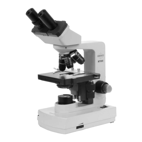
Swift M2252DGL Series User manual


1
SWIFT SERIES M2252DGL MICROSCOPE
The M2252DGL Series is ideal for elementary to high school classrooms.
Built to withstand student use, this series has locked-on eyepieces,
objectives, illuminator housing and a “slip-clutch” focusing system to
protect gears from over-focusing. The M2252DGL Series incorporates a
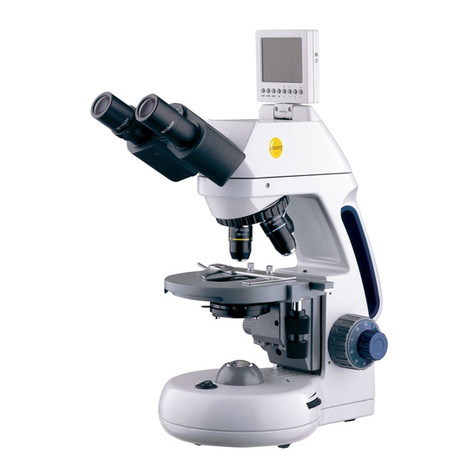
digital camera into the monocular head with a maximum resolution of
1280 X 1040 and LED illumination for efficient, cool, white light that
rarely needs to be replaced.

2
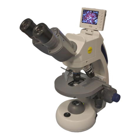
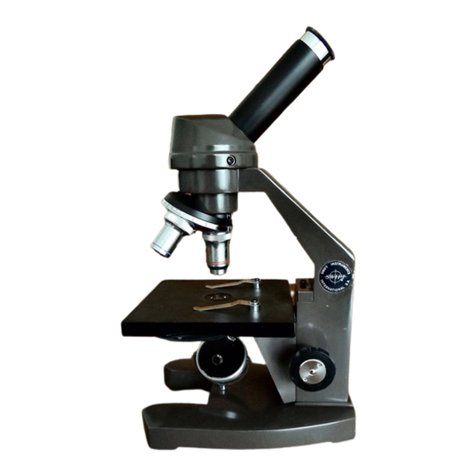
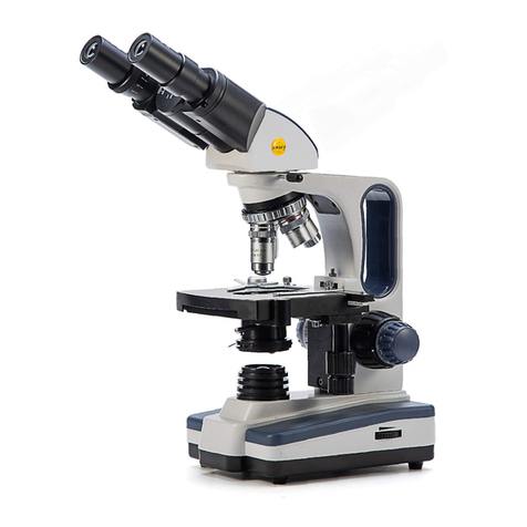
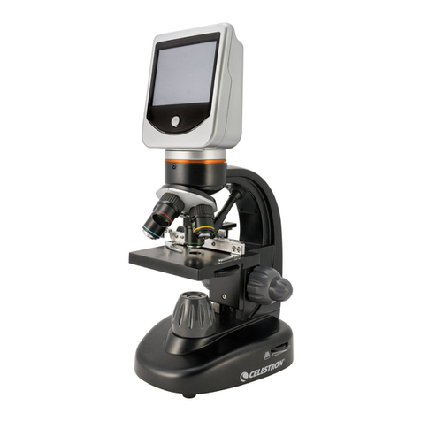
PICTURED M2252DGL

3
COMPONENTS OF THE MICROSCOPE
ARM – the vertical column (attached to the base) which supports the
stage and contains the coarse and fine adjusting knobs and focusing
mechanism.
BASE – the housing and platform of the instrument to which the arm is
attached. The base stands on rubber feet and contains the illuminator
assembly. The bulb replacement part number is printed on the underside
of the base.
COARSE FOCUS CONTROLS – this model is a stage focusing model
meaning the stage moves up or down by means of a brass rack and steel
pinion gear to bring the specimen into focus. The movement is achieved
by two large knobs on the sides of the arm. In order to prevent gear
damage, the focus control is equipped with a slip clutch that allows
slippage at both ends of the focusing range. The system is also furnished
with a tension control to prevent “stage drift”.
CONDENSER – the condenser is mounted in the stage and it is used in
conjunction with the iris diaphragm. The function of the condenser is to
provide full illumination to the specimen plane and to enhance the
resolution and contrast of the object being viewed.
EYEPIECE – the upper optical element that further magnifies the primary
image of the specimen and brings the light rays in focus at the eyepoint.
FINE FOCUS CONTROLS – the fine focusing knobs, located on either side
of the microscope, in front of and slightly lower than the coarse focusing
knobs, are used for precise focusing adjustments once the specimen has
been brought into view with the coarse focus controls
HEAD – it is the top portion of the microscope that contains the
refracting prisms and the eyepiece tube. The eyepiece is locked onto the
eyepiece tube with a set screw. The head rotates allowing operation of
the microscope from the front or the back, whichever is more convenient,
or allows the microscope to be shared by simply rotating the head.
ILLUMINATION INTENSITY KNOB – allows the user to control the
brightness of the LED illumination system

4
IRIS DIAPHRAGM - a round multi-leaf device mounted below the
condenser which is controlled by a lever. It is similar to a camera shutter
and controls the amount of light entering the condenser, allowing the
user to control contrast.
NOSEPIECE – a revolving turret that holds the objective lenses,
permitting changes in magnification by rotating different powered
objective lenses into the optical path.
OBJECTIVES – the optical systems which magnify the primary image of
the instrument. Typical magnifications are 4X, 10X, and 40X.
ON/OFF SWITCH – turns the illuminator electrical power on or off
STAGE – the platform on which the specimen slide is placed. The
standard version comes equipped with locked-on stage clips, and is
pre-drilled to accept an optional mechanical stage.
TERMINOLOGY
“COATED” LENS – in attempting to transmit light through glass, much of
the light is lost through reflection. Coating a lens increases the light
transmission by reducing or eliminating reflection, thus allowing more
light to pass through.
EYE POINT or EYE RELIEF – the distance from the eye lens of the
eyepiece to your eye where a full field of view is seen.
FIELD OF VIEW – the actual circular area seen through the eyepiece.
PARFOCAL – a term applied to objectives when very little fine focusing is
needed to bring the specimen into focus when changing objectives.
RESOLUTION or RESOLVING POWER – the ability of a lens to define the
details of the specimen at a maximum magnification. This is governed by
the N.A. (Numerical Aperture) of the lens. For example, a 40X objective
with N.A. 0.65 has a maximum resolving power of 650X, equal to 1000
times the N.A. This rule of N.A.x1000 is true of all achromatic objectives.
WORKING DISTANCE – the distance from the lens of the objective to the
cover slip on the slide, when the specimen is in focus.

5
USING YOUR MICROSCOPE
Once you have learned the terminology, the operation of the microscope
is simple. By following these easy steps, you will be able to begin
studying the specimen quickly and easily:
1. Use the slide holder to secure the slide in place. Be sure the specimen
is directly over the opening in the stage.
2. Rotate the nosepiece to place the lowest power 4X objective over the
specimen. Be sure the objective “clicks” into position.
3. While viewing through the eyepiece, rotate the coarse focusing knob
to bring the specimen into view. Next, sharpen the focus using the
fine focus knob.
4. If the image of the specimen appears pale, the iris diaphragm should
be closed slightly. This will increase contrast in the specimen’s
image. If the specimen appears dark, slightly open the iris diaphragm.
5. Use the mechanical stage controls to position the specimen directly
into the center of the field of view.
6. Rotate the nosepiece to the highest power objective. A slight turn of
the fine focusing knob may be required to bring the image of the
specimen into sharp focus. Once the specimen is in focus with the
highest power objective, it will be in focus with each lower power
objective.
EYEPIECE OBJECTIVE MAGNIFICATION
FIELD OF VIEW
W10X 4X,10X,40X 40X,100X,400X
4.10mm,1.65mm,
0.41 mm

6
DIGITAL PHOTOGRAPHY
The M2252DGL Series microscope features a built-in 1280 X 1024 pixel
digital camera to capture still images or video clips onto a computer. In
order to use the camera, the software must first be installed on a
computer. The minimum computer requirements to use the camera is
having an available USB 2.0 port and either Windows XP or Mac OS X
operating systems installed on the computer. Instructions on how to
install and use the software is included on the software CD that was
packaged with the M2252DGL Series microscope.
M2252DGL PARTS AND ACCESSORIES
MA10071 4XDObjective
MA10072 10XDObjective
MA10073S 40XRDObjective
MA10074 100XRDObjective
MA10512 W10XEyepiece
MA10513 W10XEyepiecewithpointer
MA14283 ColdHolder(Pair)
MA2215 3.4V,.06W
MA336 Dustcover

7
CARE OF YOUR SWIFT SERIES M2252DGL MICROSCOPE
Swift M2252DGL microscope is designed to function satisfactorily with
minimum maintenance. Certain components should be cleaned
frequently to ensure ease of viewing.
CLEANING – the front lens of the objectives (particularly the 40XRD and
100XRD) should be cleaned after use. First brush with a soft, camel hair
brush or blow off with clean compressed air to remove dust particles.
Then wipe gently with a soft lens tissue, moistened with optical cleaner
(eyeglass or camera lens) or clean water and immediately dry with a
clean lens paper.
CAUTION - Objectives should never be disassembled by the user. If
repairs or internal cleaning should be necessary, this should only be done
by a qualified, authorized technician.
The eyepiece may be cleaned in the same manner as the objectives,
except in most cases optical cleaner will not be required. In most
instances breathing on the eyepiece to moisten the lens and wiping dry
with a clean lens tissue is sufficient to clean the surface. Lenses should
never be wiped while dry as this will surely scratch or otherwise mar the
surface of the glass.
The finish of the microscope is hard epoxy and is resistant to acids and
reagents. Clean this surface with a damp cloth and mild detergent.
Periodically, the microscope should be disassembled, cleaned and
lubricated. This should only be done by a qualified, authorized
technician.
DUST COVER AND STORAGE – All microscopes should be protected from
dust by a dust cover when in storage or not in use. A dust cover is the
most cost-effective microscope insurance you can buy. Ensure that the
storage space is tall enough to allow the microscope to be placed into
the cabinet or onto a shelf without making undue contact with the
eyepieces. Never store microscopes in cabinets containing chemicals,
which may corrode your microscope. Also, be sure that the objectives
are placed in the lowest possible position and the rotating head is turned
inward and not protruding from the base. Microscopes with mechanical
stages should be adjusted toward the center of the stage to prevent the
moveable arms of the mechanical stage from being damaged during
storage in the cabinet.
8
BULB REPLACEMENT - To prolong the life of the bulb you should always
turn off the unit when not in use.
To replace an LED, you must first turn the power off and unplug the
microscope’s electrical cord from the electrical socket and remove
any slides on the stage. Use the small allen wrench (.09mm) that was
included with the microscope to loosen the set screws that hold the
black plastic illuminator housing onto the base of the microscope.
Remove the illuminator housing to expose the LED. Simply pull the LED
straight up to remove it from the light socket. Align the 2 metal socket
pins with the holes at the bottom of the new LED and push the LED onto
the socket. Re-install the illuminator housing.
TENSION CONTROL OF FOCUSING MOVEMENT
The focus tension is easily adjusted by using the collar found on the
coarse focusing controls, between the knob and upright support. A
clockwise turn of this collar moves it toward the upright support and
increases tension, while a counter clockwise turn moves the collar
toward the knob and decreases tension.
COMMON PROBLEMS IN MICROSCOPY
A. PROBLEM: The illuminator light does not come on
CORRECTION:
1. Make sure the microscope is plugged into a functional electrical
socket.
2. The bulb may need to be replaced. See “Bulb Replacement” on
page7.
B. PROBLEM: Image appears “washed out” or weak.
CORRECTION:
1. Slightly close the iris diaphragm.
2. Objective lens is dirty. Clean as described under “Cleaning”.
3. Eyepiece is dirty. Clean as described under “Cleaning”.
C. PROBLEM: Dust or hairs seem to be moving in the image.
CORRECTION: Disc diaphragm is at too small an aperture. Rotate to
larger aperture.

9
D. PROBLEM: Unable to bring specimen into focus.
CORRECTION:
1. Eye lens of the eyepiece is partially unscrewed. Remove the
eyepiece and screw the two sections together.
2. The nosepiece may need to be rotated to “click” an objective into
the correct position.
3. The specimen may not be centered properly on the stage and
needs to be re-positioned to be in the optical path
E. PROBLEM: Image of the specimen goes out of the focus all by itself.
CORRECTION: Use the tension control collar to tighten the focusing
mechanism found on the coarse focus spindle.
F. PROBLEM: Focusing knobs turn with difficulty even with tension-
collar loosened.
CORRECTION: Microscope should be disassembled, cleaned and
re-lubricated by a qualified, authorized technician.


Table of contents
Other Swift Microscope manuals

Swift
Swift STELLAR 1 Series User manual

Swift
Swift S30 Series User manual

Swift
Swift M3-M User manual

Swift
Swift SW380 Series User manual

Swift
Swift M6001CL User manual

Swift
Swift SW200DL User manual

Swift
Swift M10D Series User manual

Swift
Swift SW350 Series User manual

Swift
Swift SW150 User manual

Swift
Swift M3 User manual

Swift
Swift SM100 Series User manual

Swift
Swift M27LED Series User manual

Swift
Swift S7 Series User manual

Swift
Swift M3500 SERIES User manual

Swift
Swift SM91 User manual

Swift
Swift SM100 Series User manual

Swift
Swift SW380B User manual

Swift
Swift M15 Series User manual

Swift
Swift SW350B User manual

Swift
Swift M970 series User manual