4
✓
Welcome to SWIFTY power assisted cycling
Essentially your new electric bike works exactly the same as a standard bike,
peddling to propel the bike forward using the gears to suit the terrain and the
speed you want to go....only now you have an electric power assistance at
your ngertips to take the strain out of those tough uphill struggles and
making cycling a much more pleasant experience.
Simply explained this is how your electric bike works.
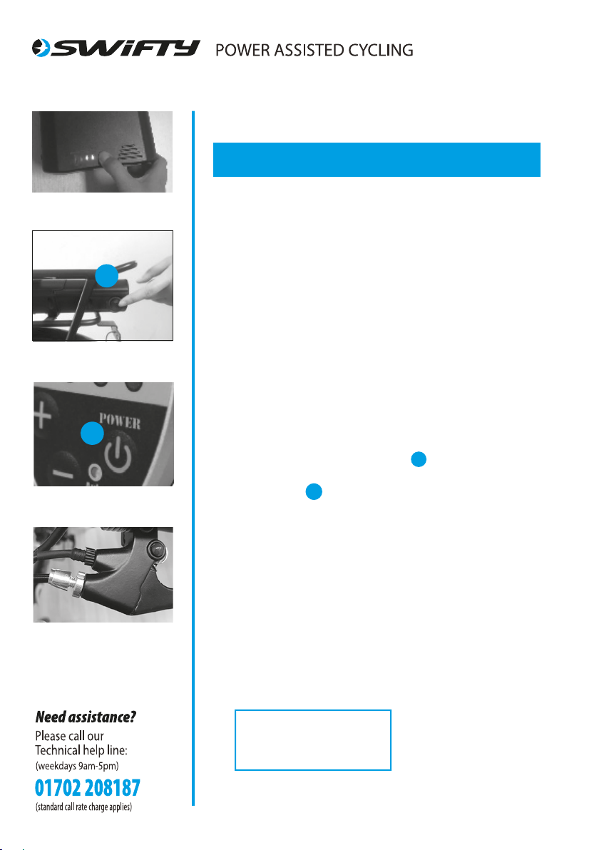
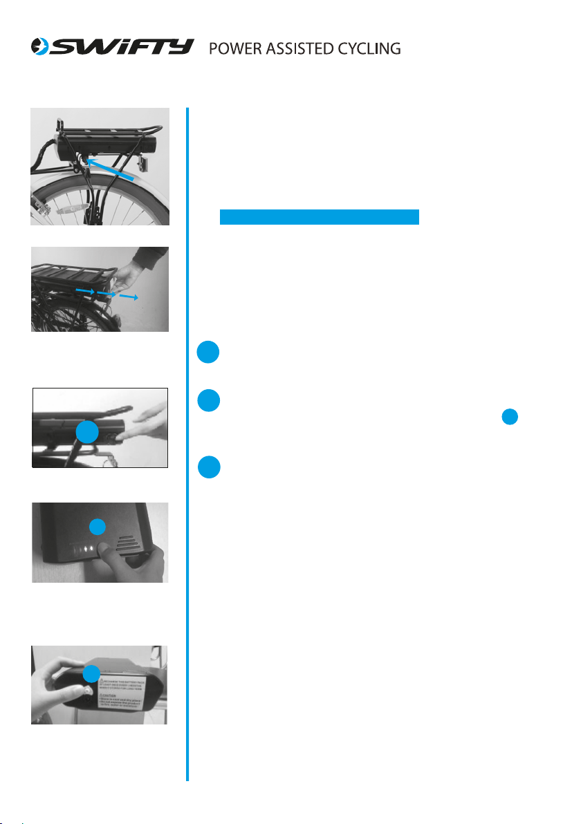
1. Switch the battery to ON, with the switch on the side left-hand side of the
battery.
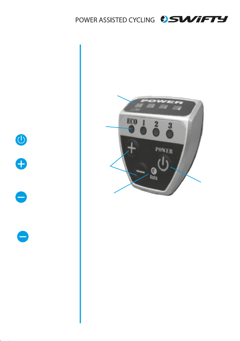
2. Switch the power on by pressing the‘POWER’ button on your controller on
the handlebars.
3. As you begin to pedal a sensor will read the level of eort needed to turn
the wheels of your bike.
4. After one complete turn of the pedal the electric motor kicks in making
pedaling much easier.
5. There are 3 setting on your controller on the handlebar, allowing you to set
the level of assistance you require. For example: Riding up a hill you’ll
probably use‘level 3’, mode.
6. Change the level of assistance you need, any time and as often as you wish.
7. The motor works to assist pedalling, stop pedalling and the motor stops
too.
8. Applying the brakes cuts the motor
9. You can also choose to switch the assist OFF and ON on the controller at any
point in your journey. This helps to save battery power if its not needed.
The more you use the assist, the more power it uses, each rider is dierent so
gures can vary considerably with dierent rider weight and the terrain you
ride. Generally with normal use, you should be able to obtain around 20 miles,
before you need to re-charge your battery.
We Recommend that you get used to your new e.bike and the level of assist
you place on it, you’ll soon be able to work out how long a journey you can
make and safely return under assist. You can of course ride as you would a
normal bike if the charge runs out.
The A-weighted emission sound pressure level at the Rider’s ears is
less than 70dB (A).
Firstly may we congratulate you on
purchasing your new electric power
assisted e.bike.
Please take time to read your manual.
We have tried to write it in a way that is
simple and easy to follow, whilst
explaining how your bike works and
how it is maintained.
At any point if you feel you need help
we have a tehnical helpline for support.
Please call our
Technical help line:
(weekdays 9am-5pm)
(standard call rate charge applies)