2
1. INTRODUCTION
Respirator system is intended to be used to provide protection when the user working in
the contamination environment. The equipment is able to filter the contaminate air via
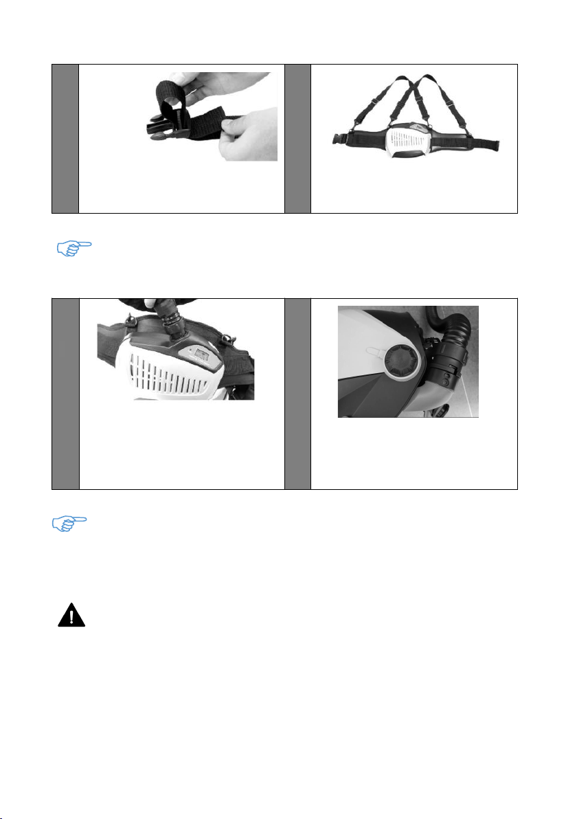
the filter build in to the blower and then supply fresh air from breathing tube to the
welding faceshield, so that the user can continually working in contamination
environment. It is a combined face and breathing protection device for increased safety
and comfort during welding. Please read these instructions carefully before unpacking.
For proper use, see user instructions or contact manufacturers for help.
2. APPROVALS
The system complies with the requirements of PPE Regulation 2016/425 and
European Standard EN 12941: 1998+A2:2008 class TH3 P R S L . The respirator
system is designed to provide a supply of filtered air via a breathing tube to a welding
headpiece. The equipment can be used in environment that requires a class TH3P
breathing protection device. It protects against articulate contamination.
All components used in respirator system must be manufacturer approved parts, and
must be used in accordance with the instructions in this manual.
1. The approval is not valid if the product is incorrectly used together
with non-approved parts or components.
2. Only the particle filter and pre-filter can be used together with this
system. Filters fromother manufacturersshould under nocircumstances
be used.
PAPR PRECAUTIONS
Notified Body: Vyzkumny ustav bezpecnosti prace, v. v. i., Jeruzalémská 1283/9, 11
0 00 Praha 1, Czech Republic (Notified body number 1024)
3
3.WARNING AND LIMITATIONS TO USE
Before each use, inspect the respirator system for damage and verify it operates
properly. Before using the respirator system, test air flow to verify it is providing an
adequate volume of air.
Always wear the respirator system and do not remove the head top or turn off the air
filter unit until outside the contaminated area, otherwise, there is a risk of high
concentration of CO2and oxygen level in the head top will fall, thus little or no protection
is given.
If you are not sure about the concentration of pollution, or about equipment performance,
ask the industrial safety engineer.
he manufacturer is not responsible for injury due to the following
incorrect use or incorrect choice of equipment.
Warning:
This respirator devices should be used with well trained person and qualified person
only.
Before using the devices ensure you have understood that at very high work rates the
pressure in the device may become negative at peak inhalation flow.
Before and during using the devices, attention shall be drawn to possible incorrect use
and, where appropriate, the possibility of looped hoses and/or cables becoming caught
up.
Before or during using the devices if the devices in the power-off state little or no
respirator protection is to be expected, and that this is considered to be an abnormal
situation.
Please leave the work place and remove the headgear, when the devices in the
power-off state a rapid build-up of carbon dioxide and depletion of oxygen within the
hood may occur.
The filters shall only be fitted to the turbo unit and not directly to the helmet/hood.
The user should not confuse the markings on a filter relating to any standard other than
EN 12941 with the classification of this device when used with this filter.
DO NOT use SparX Air with the blower unit switched off.