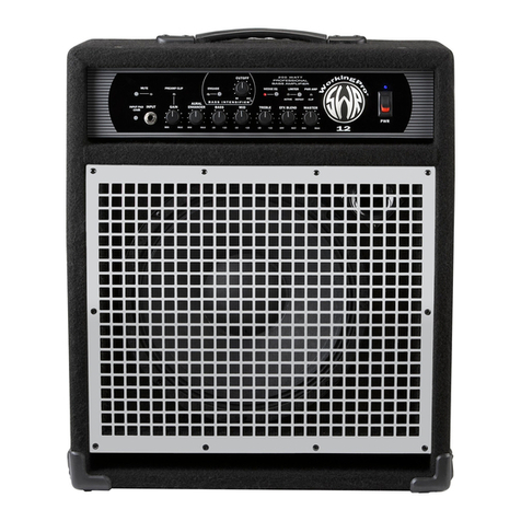
SWR WORKINGMAN'S 10 User manual

WORKINGMAN’SWORKINGMAN’S
SERIESSERIES
BASS COMBOSBASS COMBOS
OWNEROWNER’’S MANUALS MANUAL
SWR • SCOTTSDALE, AZ • USA
INCLUDES:INCLUDES:
WORKINGMAN’S 10
WORKINGMAN’S 12
WORKINGMAN’S 15
’’

TABLE OF CONTENTSTABLE OF CONTENTS
WORKINGMAN’S COMBOS OWNER’S MANUAL • 11
INTRODUCTION . . . . . . . . . . . . . . . . . . . . . . . . . . . . . . . . . . . . . . . . . . . . . . . . . . .1
WORKINGMAN’S 10 . . . . . . . . . . . . . . . . . . . . . . . . . . . . . . . . . . . . . . . . . . . . . . .2
TOP PANEL FEATURES . . . . . . . . . . . . . . . . . . . . . . . . . . . . . . . . . . . . . . . . . . . . .2
REAR PANEL FEATURES . . . . . . . . . . . . . . . . . . . . . . . . . . . . . . . . . . . . . . . . . . . .4
SUGGESTED SETTINGS . . . . . . . . . . . . . . . . . . . . . . . . . . . . . . . . . . . . . . . . . . . . .6
WORKINGMAN’S 12 . . . . . . . . . . . . . . . . . . . . . . . . . . . . . . . . . . . . . . . . . . . . . . .7
FRONT PANEL FEATURES . . . . . . . . . . . . . . . . . . . . . . . . . . . . . . . . . . . . . . . . . . .7
REAR PANEL FEATURES . . . . . . . . . . . . . . . . . . . . . . . . . . . . . . . . . . . . . . . . . . .10
SUGGESTED SETTINGS . . . . . . . . . . . . . . . . . . . . . . . . . . . . . . . . . . . . . . . . . . . .13
WORKINGMAN’S 15 . . . . . . . . . . . . . . . . . . . . . . . . . . . . . . . . . . . . . . . . . . . . . .14
FRONT PANEL FEATURES . . . . . . . . . . . . . . . . . . . . . . . . . . . . . . . . . . . . . . . . . .14
REAR PANEL FEATURES . . . . . . . . . . . . . . . . . . . . . . . . . . . . . . . . . . . . . . . . . . .18
SUGGESTED SETTINGS . . . . . . . . . . . . . . . . . . . . . . . . . . . . . . . . . . . . . . . . . . . .20
IMPORTANT SAFETY INFORMATION . . . . . . . . . . . . . . . . . . . . . . . . . . . . . . . . .21
WARRANTY & SERVICE INFORMATION . . . . . . . . . . . . . . . . . . . . . . . . . . . . . . .22
COVERS & REPLACEMENT PARTS . . . . . . . . . . . . . . . . . . . . . . . . . . . . . . . . . . .22
INTRODUCTIONINTRODUCTION
Congratulations on your purchase of an SWR Workingman’s Series bass combo. By choosing an
SWR bass amplification system you have made a soundsound desicion that could very well be the best of
your life!
Just a little humor there, but true nonetheless. For over 15 years we here at SWR have been putting
everything we know about bass into the SWR product line. We’ve earned a reputation for designing and
manufacturing gear that has changed the way bassists hear themselves. That’s why you’ll find our bass
amps, cabinets, and combos on stages and in recording studios all over the world, and why you’ll hear
SWR on countless recordings, spanning all genres of music.
Inside this User Guide you’ll find specifications, features, and usage suggestions for every Workingman’s
Series bass combo we make. New SWR user and seasoned user alike will benefit from reading through
this brief but informative manual.
Thanks for choosing SWR for your bass amplification system.
Sincerely,
SWR

WORKINGMAN’S 10WORKINGMAN’S 10
80 watt, 1x10 combo amplifier with tweeter. A small yet
powerful bass cube, extremely portable. The SWR Sound
“to go.”
Speaker Complement:Speaker Complement:
(1) Custom Designed 10" SWR driver
(1) Custom Designed Piezo tweeter
Power Output:Power Output: 80 Watts RMS, 100 Watts RMS @ 4 Ohms
(with 8 ohm extension speaker)
Impedance:Impedance: 8 Ohms (internal)
Dimensions:Dimensions: 16.25" W x 14.5" H x 14" D
Weight:Weight: 32 lbs.
TOP PANEL FEATURES
INPUT JACK
This jack accepts any standard instrument cable that connects via 1/4" plugs. The Workingman’s 10
Input Jack accomodates both passive and active instruments. The high input impedance assures perfect
compatibility for all active/passive/magnetic and piezo pick-up systems.
VOLUME CONTROL
Turning the Volume Control clockwise or toward “Max” increases the volume of the Workingman’s 10.
Turning it counter-clockwise or toward “Min” decreases the volume. If the Volume Control is in the full
counter-clockwise position, no sound will be audible.
Playing your Workingman’s 10 at excessive volume can result in clipping of the power amplifier section.
If you hear distortion through your speakers, decrease the setting of the Volume Control. Clipping will not
harm the Workingman’s 10 electronics, but can cause damage to the internal speaker components and
is not recommended.
NOTE: Overdriving the Workingman’s 10 for extended periods of time can activate the amplifier’s
thermal protection circuitry, resulting in temporary loss of output.
If you require more volume than the Workingman’s single 10" speaker can provide, we recommend
adding an extension speaker cabinet with an impedance of no lessno less than 8 ohms.
AURAL ENHANCER
The Aural Enhancer was developed to bring out the fundamental low notes of the bass, reduce certain
frequencies that can “mask” fundamentals, and enhance the high-end transients. The effect becomes
more pronounced as the control is turned up. The result is a more transparent sound. Listening to a
passive bass with the control set all the way down, and then turning it all the way up, can be likened to
listening to the bass suddenly becoming “active.”
TONE CONTROL SECTION
The Workingman’s 10 Tone Control section is a three-band set of level controls centered around the fre-
quencies 80 Hz (bass), 800 Hz (mid range) and 5kHz (treble). Each control can cut or boost its band a
maximum of 15dB. Each control has a flat (center click) position that defeats its function.
In this position, the tone controls are inactive.
22 • WORKINGMAN’S COMBOS OWNER’S MANUAL

For each tone control, rotating the knob counter-clockwise from the center “click” position will reduce or
cut its designated frequency. Rotating the knob clockwise will boost its designated band or frequency.
Using the Tone Controls
To get the most out of the Tone Controls of your Workingman’s 10, it would be best to first understand
how the Aural Enhancer works, and how it interacts with the Bass, Midrange and Treble controls. Think
of it as a variable tone curve, changing with its position. As you raise the control from “0,” or the fully
counterclockwise position, you are elevating the whole range of sound (lows, mids, and highs) at fre-
quency points different than those selected for the individual Tone Controls. This remains true up to
about the “2 o’clock” position, at which point the mids start to drop off. The curves involved here are
gentle, as opposed to the very extreme curves you can create with the Tone Controls. Most significantly,
the Aural Enhancer will raise the low end at a point lower than the Bass control itself.
For a typical 4-string bass, the Bass control itself will suffice. For the 5-string player, the Aural Enhancer
will help bring out the fundamentals of your instrument (in the 30-60 Hz range). Discretion should be
used when doing this without an extension cabinet. True low fundamentals (one of the sonic signatures
of all SWR amplifiers) require lots of headroom and air motion. That’s why we recommend that 5-string
players use an extension cabinet to increase the power output of the amplifier and get more air moving.
Bass Control
The Bass control, as stated above, works in a range that will be useful under most “normal” conditions.
Its musical use might be thought of as a “fatness” control. Leaving the Aural Enhancer in a position
lower than 12 o’clock will not boost the extreme bottom so much as to make indistinct the working of
the Bass control. The overall “punch” of your instrument, from your low E-string on up about two
octaves (midway up the G-string), will be determined with this control. With passive instruments, this will
be straightforward. With active instruments having bass-boost controls, more exploration will be worth-
while. (Some active tone circuits have boost-cut controls, while others have straight boost controls).
Mid Range Control
The Mid Range control operates in a crucial area for most instruments. Many basses, particularly those
strung with roundwound strings, can have a very “honky” or nasal sound. Dropping the Mid Range con-
trol can go a long way toward smoothing out your tone. We suggest, though, that what sounds best
when you’re listening to your tone by yourself may not be what works best in a band or on a recording.
Sometimes that objectionable quality may be just the right “hair” on your note to still have an audible
presence in the track or on stage.
Treble Control
The Treble control operates in a tonal area that extends through and beyond the usual Treble control
range. It may be thought of as a “transparency” control. Boosting the control will open up the sound of
a dull instrument, particularly in conjunction with the piezo tweeter in the Workingman’s 10. However,
this is also the range of string rattle, finger slides, pickup clicks, etc. Again, we recommend you experi-
ment with the control alone with your instrument while finding your tone, and listen again in a band con-
text, both near to and away from the Workingman’s 10. Qualities such as punch, fatness, presence and
bite can be fairly well spread out. Treble, despite the broad dispersion of the piezo tweeter, is a very
directional quality. Spend some time exploring what you hear in this area as you move around.
EFFECTS BLEND
The Effects Blend control mixes the signal coming from your instrument with the sound coming from your
effect. With the Blend control fully counterclockwise, no signal from your effect will be heard. As you turn
WORKINGMAN’S COMBOS OWNER’S MANUAL • 33

this control clockwise, more of the effect can be heard in the overall sound. When the Blend control is fully
clockwise, no dry or unaffected signal is heard other than the output of your effect device.
This type of control and patching arrangement is very effective in reducing noise caused by effects
devices and in maintaining a more natural sound. If your effects device has a similar control, we
suggest leaving it set to its maximum effect/minimum dry signal position and using the Effects Blend
control for this function. Please read the “Effects Loop” section for more information.
POWER SWITCH
Pressing the Power Switch to the ON position activates the Workingman’s 10 electronics as indicated by
the LED above the switch.
REAR PANEL FEATURESREAR PANEL FEATURES
TO TUNER
The To Tuner send jack allows the user to connect their instrument tuner to the Workingman’s 10 with-
out having to unplug and go back and forth from amp to tuner to amp. This feature is isolated from the
rest of the circuitry and no other controls other than your instrument have an effect on it. Being on an
isolated sidechain also avoids loading down of the instrument, which can cause a loss
in dynamic range.
To use this feature, plug in a shielded patch cord from this jack to the INPUT of your tuning device. Turn
the amp on and you’re ready to go. If you don’t want to monitor your sound while tuning, turn down the
Volume control or position the selector switch on the back panel to the “headphones only” (middle)
position.
EFFECTS LOOP
The Effects Loop is located POST EQ in the signal path. The level appearing at the Send jack is con-
trolled by the Volume control on the front panel. If you are getting too hot a signal to the input of your
effect, reduce the level of the Volume control. By using the Volume and Effects Blend controls, optimum
performance should be easily obtainable with any effects device.
The Effects Loop is designed as a “sidechain” (parallel) function similar to those found on mixing consoles.
Use of the Effects Loop should greatly reduce noise generated by effects devices (as compared to in-line
effects loops). Additional features of this type of loop can be found below under “Receive Jack.”
Send Jack
Run a shielded patch cable from the Send jack to the input of your effects device. This jack may be
used as an additional line level output, in which case its level is determined by the setting of the Volume
control.
Receive Jack
Run a shielded patch cable from the output of your effects device to the Receive jack.
One unique feature of the Receive jack is the ability to practice along with pre-recorded music. Insert a
sound source into the Receive jack (make sure it is a mono source). Use the Effects Blend control to
mix the level of the recorded music with your instrument’s level. The combined signal will be heard
through the internal speakers or your headphones. The send jack is not used.
NOTE: Inserting a plug into the Receive jack activates the Effects Blend control by receiving a “com-
mand” through the ground created. Therefore, only a mono (2-conductor) phone plug should be
44 • WORKINGMAN’S COMBOS OWNER’S MANUAL

used. If you have a stereo (3-conductor) plug only, tie the ring and the sleeve (ground) together.
If you are not getting any “effect” through the speakers, check the position of the Effects Blend control.
EXTENSION SPEAKER JACK
Use an unshielded 2-conductor cable (NOT A GUITAR CORD!) to connect an additional speaker cabinet.
Use a high quality, heavy gauge cable of at least 18 gauge (the lower the gauge, the heavier the cable).
The impedance of the speaker should be 8 ohms or greater. If you wish to connect two additional cabi-
nets be sure their combined impedance is not less than 8 ohms (equivalent to two 16 ohm speaker
cabinets in parallel).
Recommended speaker cabs from SWR are: Workingman’s 1X10T, Workingman’s 1X15T,
Workingman’s 2X10T, Workingman’s 4X10T.
STEREO HEADPHONES JACK
By inserting a set of stereo headphones into this jack you will be able to monitor your sound or practice
without disturbing your neighbors. The headphone volume level is adjusted by the Volume control. We
suggest you begin with the Volume off (fully counterclockwise), then slowly bring the volume up to your
desired level. If you hear some distortion in your headphones that is not present with the speakers on,
turn down the volume—you are overdriving your headphones and could ruin them.
Any impedance stereo headphones will work. However, optimum impedance is 75 ohms.
THREE WAY SELECTOR SWITCH
The top position, labeled Full Range, activates both the tweeter and the 10" woofer in the
WorkingMan’s 10, as well as the extension speaker jack. This position is the most typical setting.
The middle position, labeled Headphones Only, disconnects the signal going to the internal speakers and
extension speaker jack. Use this position when listening with heaphones only or for silent tuning (refer to To
Tuner section). The Headphones jack is always active regardless of the switch’s position.
The bottom position, labeled Horn Off, disconnects the tweeter located in the upper right hand corner of
the speaker cabinet. It will not affect the 10" woofer, headphones or any extension cabinet. If you prefer
a “darker” sound or are getting a lot of fret buzz, clicks, or pick or finger noise, you may want to use this
position.
BALANCED DIRECT RECORD OUT
The Balanced XLR output is a true balanced output. No front panel controls affect its signal. The tone and
output level are controlled only by the instrument plugged into one of the input jacks. To use this feature,
run an XLR (Cannon) cable from the Balanced D.I. to the input of a tape machine, mixing console, etc.
This output is also suitable for sending a signal to a house mixer in live situations.
Wiring for the XLR connector is as follows: Pin 1 = ground, Pin 2 = +, Pin 3 = –. (American standard)
NOTE: Do not apply phantom power (48V supply) to this output. Doing so may damage the inter-
nal circuitry.
A/C LINE FUSE
The line fuse can open (blow) due to power surges or high powerline transients. This fuse will also open
in the event of an electronics failure inside your amplifier. Correct size and rating of the Line (Mains)
fuse: 3AG, 2 amp slo-blow for 120V operation (North America), and 1 amp slo-blo for 240V operation.
A/C LINE CORD RECEPTACLE
Accepts a standard A/C power cable (supplied with the Workingman’s 10 in the United States), used with
almost all current musical, professional and household electronic devices. If it becomes misplaced,
WORKINGMAN’S COMBOS OWNER’S MANUAL • 55

replacement will be easy at almost any computer, electronics or pro audio store.
NOTE: The rating for this cable is 3-conductor, 10 amperes. This is a rating of the current capacity
of the cable, designated for higher power-drawing devices like amplifiers. If replacement is neces-
sary, or if you wish to buy a longer cable, look for the rating on the cable and be sure it is at least
10 amps.

66 • WORKINGMAN’S COMBOS OWNER’S MANUAL
WORKINGMAN’SWORKINGMAN’S 1010
Suggested Settings

WORKINGMAN’S 12WORKINGMAN’S 12
120 watt, 1x12 combo amplifier with tweeter. A little powerhouse. Great
for both electric and upright basses.
Speaker Complement:Speaker Complement:
(1) Custom Designed 12" SWR driver
(1) Custom Designed Piezo tweeter
Power Output:Power Output: 120 Watts RMS, 160 Watts RMS @ 4 Ohms
(with 8 ohm extension speaker)
Impedance:Impedance: 8 Ohms (internal)
Dimensions:Dimensions: 15.5" W x 22.25" H x 15.25" D
Weight:Weight: 47 lbs.
FRONT PANEL FEATURES
BALANCED DIRECT RECORD OUT
The Balanced XLR output is a true balanced output. No front panel controls affect its signal. The tone and
output level are controlled only by the instrument plugged into one of the input jacks. To use this feature,
run an XLR (Cannon) cable from the Balanced D.I. to the input of a tape machine, mixing console, etc.
This output is also suitable for sending a signal to a house mixer in live situations.
Wiring for the XLR connector is as follows: Pin 1 = ground, Pin 2 = +, Pin 3 = –. (American standard)
TO TUNER
The To Tuner send jack allows the user to connect their instrument tuner to the Workingman’s 12 with-
out having to unplug and go back and forth from amp to tuner to amp. Like the Balanced D.I.
output, this feature is isolated from the rest of the circuitry and no other controls other than your instru-
ment have an affect on this feature. Being on an isolated sidechain also avoids loading down of the
instrument, which can cause a loss in dynamic range.
To use this feature, plug in a shielded patch cord from this jack to the INPUT of your tuning device. Turn
the amp on and you're ready to go. If you don’t want to monitor your sound while tuning, turn down the
Master Volume control or position the selector switch on the back panel to the “headphones” (middle)
position.
INPUT JACKS
Two separate and independent input jacks are provided so that the best signal-to-noise ratio can be
obtained without overloading the preamp section. The Passive input has over twice the gain than that of
the Active input. Both inputs can be used simultaneously without affecting the volume or tone of the
other. One use of these inputs would be to plug your bass into the Passive input and practice along with
a drum machine by plugging it into the Active input. A more detailed explanation of these inputs follows.
Passive Input
This input can and should be used if your instrument has passive electronics (no built-in preamp). Some
pickups employ batteries for operation and will work perfectly using this input. Technically speaking, this
input should be used if your instrument has an output voltage of 1 volt RMS or LESS. Consult the owner’s
manual that came with your instrument or ask the manufacturer if you are unsure.
NOTE: Generally speaking, you should try the Passive input jack first. If you hear a small amount of
distortion and the Preamp Clip LED is not activated, try using the Active input jack. Some passive
WORKINGMAN’S COMBOS OWNER’S MANUAL • 77

pickups DO distort. Because of the hi-fi nature of all SWR products, even the smallest amount of
distortion originating at the source (instrument) may be heard.
Active Input
The Active input jack should be used with instruments having a built-in (on-board) preamp that will pro-
duce signals over 1 volt RMS. Some really “hot” pickups installed in your instrument may find the Active
input more compatible. The best judge is your own ears.
NOTE: Using the Active input with passive basses may result in a loss of high-end transients.
Players who roll off their high-end starting at around 2k to 3kHz may find this input more to their
liking.
If your hear some distortion from your active bass and are using the Active input jack, check your
battery. Also, make sure the Preamp Clip LED is not lighting.
PREAMP CLIP LED
The Preamp Clip LED will light whenever the Preamp, Tone section or output buffer reach clipping (that
is, run out of headroom). In the event the Preamp Clip LED lights, turn down the Gain control. Since the
Preamp Clip also monitors the Tone section, boosting any one of the tone controls can cause the LED to
activate. Again, turn down the Gain control if this happens.
NOTE: Constant clipping of the preamp will not harm the electronics in your Workingman’s 12.
However, damage can occur to speakers due to near-DC content present in a clipped waveform.
GAIN CONTROL
The Gain control adjusts the volume of the preamp section. After the Tone controls, Aural Enhancer and
any effects you may be using have been set to your liking, the Gain control should be set to where the
Preamp Clip LED barely flashes upon hitting your loudest note. After setting the Gain, use the Master
Volume to set the desired volume level. Using these controls in this manner assures the maximum sig-
nal-to-noise ratio with no distortion caused by the preamp circuits clipping. Since the Gain control is
similar to a “pad,” a small amount of signal will get through with the Gain control turned all the way
down. The Gain also adjusts the level sent to the Effects send jack. If your effect is being overdriven,
turn down the Gain control.
TONE CONTROL SECTION
The Workingman’s 12 Tone Control section is a three-band set of level controls centered around the fre-
quencies 80 Hz (Bass), 800 Hz (Mid Range) and 5kHz (Treble). Each control can cut or boost its band a
maximum of 15dB. Each control has a flat (center “click”) position that defeats its function. In this posi-
tion, the tone controls are inactive.
For each tone control, rotating the knob counter-clockwise from the center “click” position will cut (reduce)
its designated frequency. Rotating the knob clockwise will boost its designated band or frequency.
Using the Tone Controls
To get the most out of the Tone Controls of your Workingman’s 12, it would be best to first understand
how the Aural Enhancer works, and how it interacts with the Bass, Mid Range and Treble controls. Think
of it as a variable tone curve, changing with its position. As you raise the Aural Enhancer from “0,” or its
fully counterclockwise position, you are elevating the whole range of sound (lows, mids, and highs) at fre-
quency points different than those selected for the individual Tone Controls. This remains true up to about
the “2 o’clock” position, at which point the mids start to drop off. The curves involved here are gentle, as
opposed to the very extreme curves you can create with the Tone Controls.
88 • WORKINGMAN’S COMBOS OWNER’S MANUAL

Most significantly, the Aural Enhancer will raise the low end at a point lower than the Bass control itself.
For a typical 4-string bass, the Bass control itself will suffice. For the 5-string player, the Aural Enhancer
will help bring out the fundamentals of the instrument, in the 30-60 Hz range. Discretion should be
used when doing this without an extension cabinet. True low fundamentals (one of the sonic signatures
of all SWR amplifiers) require lots of headroom and air motion. That’s why we recommend that 5-string
players use an extension cabinet to increase the power output of the amplifier and get more air moving.
Bass Control
The Bass control, as stated above, works in a range that will be useful under most “normal” conditions.
Its musical use might be thought of as a “fatness” control. Leaving the Aural Enhancer in a position
lower than 12 o’clock will not boost the extreme bottom so much as to make indistinct the effect of the
Bass control. The overall “punch” of your instrument, from your low E-string on up about two octaves
(midway up the G- string), will be determined with this control. With passive instruments, this will be
straightforward. With active instruments having bass-boost controls more exploration will be worthwhile.
(Some active tone circuits have boost/cut controls, while others have straight boost controls).
Mid Range Control
The Mid Range control operates in a crucial area for most instruments. Many basses, particularly those
strung with roundwound strings, can have a very “honky” or nasal sound. Dropping the Mid Range con-
trol can go a long way toward smoothing out your tone. We suggest, though, that what sounds best
when your listening to your tone by yourself may not be what works best in a band or recording.
Sometimes that objectionable quality may be just the right “hair” on your note to still have an audible
presence in the track or on stage.
Treble Control
The Treble control operates in a tonal area that extends through and beyond the usual Treble control
range. It may be thought of as a “transparency” control. Boosting the control will open up the sound of
a dull instrument, particularly in conjunction with the piezo tweeter. However, this is also the range of
string rattle, finger slides, pickup clicks, etc. Again, we recommend you experiment with the control
alone with your instrument, and listen again in a band context, both near to and away from the
WorkingMan’s 12. Qualities like punch, fatness, presence and bite can be fairly well spread out. Treble,
despite the broad dispersion of the piezo tweeter, is a very directional quality. Spend some time explor-
ing what you can hear in this area as you move around.
AURAL ENHANCER
The Aural Enhancer was developed to bring out the fundamental low notes of the bass, reduce certain
frequencies that can “mask” fundamentals and enhance the high-end transients. The effect becomes
more pronounced as the control is turned up. The result is a more transparent sound. Listening to a
passive bass with the control set all the way down, and then turning it all the way up, can be likened to
listening to the bass suddenly become “active.”
EFFECTS BLEND CONTROL
The Effects Blend control mixes the signal coming from your instrument with the sound coming from
your effect. With the Blend control fully counter-clockwise, no signal from your effect will be heard.
As you turn this control clockwise, more of the effect can be heard in the overall sound. When the Blend
control is fully clockwise, no dry or unaffected signal is heard other than the output of your effect device.
WORKINGMAN’S COMBOS OWNER’S MANUAL • 99

This type of control and patching arrangement is very effective in reducing noise caused by effects
devices and in maintaining a more natural sound. If your effects device has a similar control, we
suggest leaving it set to its maximum effect/minimum dry signal position and using the Effects Blend
control for this function. Please read the “Effects Loop” section for more information.
MASTER VOLUME
The Master Volume control adjusts the signal level going to the power amplifier. It DOES NOT control the
output of the effects send jack or Balanced Direct Record XLR output. It DOES affect the output of the
internal speakers, headphones, and extension speaker jack. Losses caused by effects units can be
recovered by increasing the Master Volume.
NOTE: If you need more volume than the Workingman’s single 12"can provide, add an extension
speaker cabinet. The extension cabinet should have an impedance of 8 ohms or greater.
LIMITER CIRCUIT
The Workingman’s 12 Limiter Circuit is a soft knee type limiter that prevents distortion of attack tran-
sients or peaks. The Limiter can be used as an effect and is also helpful in preventing speaker damage.
The circuit is located after (post) the master volume and before (pre) the power amplifier; it is driven by
the Master Volume control. Its threshold (starting point) is preset by the factory so that the user can get
maximum overall apparent volume without unduly overdriving the power amplifier.
LIMITER LED
The Limiter LED lights when your signal has reached the Limiter threshold, letting you know that the
Limiter circuit has been activated.
NOTE: No harm is being done to your amplifier when this LED lights or stays lit.
POWER SWITCH
Pressing the Power Switch to the ON position activates the Workingman's electronics as indicated by the
red LED above the switch.
REAR PANEL FEATURESREAR PANEL FEATURES
EFFECTS LOOP
The Effects Loop is located POST EQ and PRE Master Volume in the signal path. The level appearing at
the Send jack is controlled by the Gain control on the front panel. If you are getting too hot a signal to
the input of your effect, reduce the level of the Gain control and raise the level of your Master Volume
control to retain similar overall volume levels. By using the Gain, Master Volume and Effects Blend con-
trols, optimum performance should be easily obtainable with any effects device.
The Effects Loop is designed as a “sidechain” (parallel) function similar to those found on mixing con-
soles. Use of the Effects Loop should greatly reduce noise generated by effects devices (as
compared to in-line effects loops). Additional features of this type of loop can be found below under the
“Receive Jack” section.
Send Jack
Run a shielded patch cable from the Send jack to the input of your effects device. This jack may be
used as an additional line level output, in which case its level is determined by the setting of the Gain
control.
1010 • WORKINGMAN’S COMBOS OWNER’S MANUAL

Receive Jack
Run a shielded patch cable from the output of your effects device to the Receive jack.
One unique feature of the Receive jack is the ability to practice along with pre-recorded music. Insert a
sound source into the Receive jack (make sure it is a mono source). Use the Effects Blend control to
mix the level of the recorded music with your instrument’s level. The combined signal will be heard
through the internal speakers or your headphones. The send jack is not used.
NOTE: Inserting a plug into the Receive jack activates the Effects Blend control by receiving a
“command” through the ground created. Therefore, only a mono (2-conductor) phone plug should
be used. If you have a stereo (3-conductor) plug only, tie the ring and the sleeve (ground) togeth-
er.
If you are not getting any “effect” through the speakers, check the position of the Effects Blend control.
EXTENSION SPEAKER JACK
Use an unshielded 2-conductor cable (NOT A GUITAR CORD!) to connect an additional speaker cabinet.
Use a high quality, heavy gauge cable of at least 18 gauge (the lower the gauge, the heavier the cable).
The impedance of the speaker should be 8 Ohms or greater. If you wish to connect two additional cabi-
nets be sure their combined impedance is not less than 8 ohms (equivalent to two 16 ohm speaker
cabinets in parallel).
Recommended speaker cabs from SWR are: Workingman’s 1X10T, Workingman’s 1X15T,
Workingman’s 2X10T, Workingman’s 4X10T, Son Of Bertha, Goliath III and Big Ben.
STEREO HEADPHONES JACK
By inserting a set of stereo headphones into this jack you will be able to monitor your sound or practice
without disturbing your neighbors. The headphone volume level is adjusted by the Master Volume. We
suggest you begin with the Master Volume off (fully counterclockwise), then slowly bring the volume up to
your desired level. If you hear some distortion in your headphones that is not present with the speakers
on, turn down the volume—you are overdriving your headphones and could ruin them.
Any impedance stereo headphones will work. However, optimum impedance is 75 ohms.
THREE WAY SELECTOR SWITCH
The top position, labeled Full Range, activates both the tweeter and the 12" woofer in the
Workingman’s 12, as well as the extension speaker jack. This position is the most typical setting.
The middle position, labeled Headphones Only, disconnects the signal going to the internal speakers and
extension speaker jack. Use this position when listening with heaphones only or for silent tuning (refer to To
Tuner section). The Headphones jack is always active regardless of the switch’s position.
The bottom position, labeled Horn Off, disconnects the tweeter located in the upper right hand corner of
the speaker cabinet. It will not affect the 12" woofer, headphones or any extension cabinet. If you prefer
a “darker” sound or are getting a lot of fret buzz, clicks, or pick or finger noise, you may want to use this
position.
A/C LINE FUSE
The line fuse can open (blow) due to power surges or high powerline transients. This fuse will also open
in the event of an electronics failure inside your amplifier. Correct size and rating of the Line (Mains)
fuse: 3AG, 3 amp slo-blow for 120V operation (North America), and 1 1/2 amp slo-blo for 240V
operation.
WORKINGMAN’S COMBOS OWNER’S MANUAL • 1111

A/C LINE CORD RECEPTACLE
Accepts a standard A/C power cable (supplied with the Workingman’s 12 in the United States), used
with almost all current musical, professional and household electronic devices. If it becomes misplaced,
replacement will be easy at almost any computer, electronics, or pro audio store.
NOTE: The rating for this cable is 3-conductor, 10 amperes. This is a rating of the current capacity
of the cable, designated for higher power-drawing devices like amplifiers. If replacement is neces-
sary, or if you wish to buy a longer cable, look for the rating on the cable and be sure it is at least
10 amps.
1212 • WORKINGMAN’S COMBOS OWNER’S MANUAL

WORKINGMAN’SWORKINGMAN’S 1212
Suggested Settings
WORKINGMAN’S COMBOS OWNER’S MANUAL • 1313

WORKINGMAN’S 15WORKINGMAN’S 15
200 watt, 1x15 combo amplifier with tweeter. Perfect for small to
medium size gigs. Lightweight!
Speaker Complement:Speaker Complement:
(1) Custom Designed 15" SWR driver
(1) Custom Designed Piezo tweeter
Power Output:Power Output: 160 Watts RMS, 200 Watts RMS @ 4 Ohms
(with 8 ohm extension speaker)
Impedance:Impedance: 8 Ohms (internal)
Dimensions:Dimensions: 20.75" W x 27.625" H x 16.25" D
Weight:Weight: 55 lbs.
FRONT PANEL FEATURES
BALANCED DIRECT RECORD OUT
The Balanced XLR output is a true balanced output. No front
panel controls affect its signal. The tone and output level are con-
trolled only by the instrument plugged into one of the input jacks.
To use this feature, run an XLR (Cannon) cable from the Balanced D.I. to the input of a tape machine,
mixing console, etc. This output is also suitable for sending a signal to a house mixer in live situations.
Wiring for the XLR connector is as follows: Pin 1 = ground, Pin 2 = +, Pin 3 = –. (American standard)
TO TUNER
The To Tuner send jack allows the user to connect their instrument tuner to the Workingman’s 15 with-
out having to unplug and go back and forth from amp to tuner to amp. Like the Balanced D.I.
output, this feature is isolated from the rest of the circuitry and no other controls other than your instru-
ment have an affect on it. Being on a sidechain (isolated) also avoids loading down of the instrument,
which can cause a loss in dynamic range.
To use this feature, plug in a shielded patch cord from this jack to the INPUT of your tuning device. Turn
the amp on and you’re ready to go. If you don’t want to monitor your sound while tuning, turn down the
Master Volume control or position the selector switch on the front panel to the “headphones” (middle)
position.
INPUT JACKS
Two separate and independent input jacks are provided so that the best signal-to-noise ratio can be
obtained without overloading the preamp section. The Passive input has over twice the gain than that of
the Active input. Both inputs can be used simultaneously without affecting the volume or tone of the
other. One use of these inputs would be to plug your bass into the Passive input and practice along with
a drum machine by plugging it into the Active input. A more detailed explanation of these inputs follows.
Passive Input
This input can and should be used if your instrument has passive electronics (no built-in preamp).
Technically speaking, this input should be used if your instrument has an output voltage of 1 volt RMS or
LESS. Consult the owner’s manual that came with your instrument or ask the manufacturer
if you are unsure.
1414 • WORKINGMAN’S COMBOS OWNER’S MANUAL

NOTE: Generally speaking, you should try the Passive input jack first. If you hear a small amount of
distortion and the Preamp Clip LED is not activated, try using the Active input jack. And please note,
some passive pickups DO distort. Because of the hi-fi nature of all SWR products, even the smallest
amount of distortion originating at the source (instrument) may be heard.
Active Input
The Active input jack should be used with instruments having a built-in (on-board) preamp that will pro-
duce signals over 1 volt RMS. Some really “hot” pickups installed in your instrument may find the Active
input more compatible. The best judge is your own ears.
NOTE: Using the Active input with passive basses may result in a loss of high-end transients.
Players who roll off their high-end starting at around 2kto 3kHz may find this input more to their
liking.
If your hear some distortion from your active bass and are using the Active input jack, check your
battery. Also, make sure the Preamp Clip LED is not lighting.
PREAMP CLIP LED
The Preamp Clip LED will light whenever the Preamp, Tone section or output buffer reach clipping (that
is, run out of headroom). In the event the Preamp clip indicator lights, turn down the Gain
control. Since the Preamp Clip also monitors the Tone section, boosting any one of the tone controls
can cause the LED to activate. Again, turn down the Gain control if this happens.
NOTE: Constant clipping of the preamp will not harm the electronics in your Workingman’s 15.
However, damage can occur to speakers due to near-DC content present in a clipped waveform.
GAIN CONTROL
The gain control adjusts the volume of the preamp section. After the Tone controls, Aural Enhancer and
any effects you may be using have been set to your liking, the Gain control should be set to where the
Preamp Clip LED barely flashes upon hitting your loudest note. After setting the Gain, use the Master
Volume to set the desired volume level. Using these controls in this manner assures the maximum sig-
nal-to-noise ratio with no distortion caused by the preamp circuits clipping. Since the Gain control is
similar to a “pad,” a small amount of signal will get through with the Gain control turned all the way
down. The Gain also adjusts the level sent to the Effects send jack. If your effect is being overdriven,
turn down the Gain control.
TONE CONTROL SECTION
The Workingman’s 15 Tone Control section is a three-band set of level controls. The Bass and Treble
controls are centered around the frequencies 80 Hz (Bass), and 5kHz (Treble). The Mid Range controls
comprise a level control and a frequency control knob.
Each control (except Mid Frequency) can cut or boost its band a maximum of 15dB. Each control has a
flat (“center click”) position that defeats its function. In this position, the tone controls are inactive.
For each tone control (except Mid Frequency), rotating the knob counter-clockwise from the center click
position will reduce or cut its designated frequency. Rotating the knob clockwise will boost its designated
band or frequency.
Using the Tone Controls
To get the most out of the Tone Controls of your Workingman’s 15, it would be best to first understand
how the Aural Enhancer works, and how it interacts with the bass, mid range and treble controls. Think
of it as a variable tone curve, changing with its position. As you raise the control from its “0,” or fully
WORKINGMAN’S COMBOS OWNER’S MANUAL • 1515

counterclockwise position, you are elevating the whole range of sound (lows, mids, and highs) at
frequency points different than those selected for the individual Tone Controls. This remains true up to
about the “2 o’clock” position, at which point the mids start to drop off. The curves involved here are
gentle, as opposed to the very extreme curves you can create with the Tone Controls.
Most significantly, the Aural Enhancer will raise the low end at a point lower than the Bass control itself.
For a typical 4-string bass, the Bass control itself will suffice. For the 5-string player, the Aural Enhancer
will help bring out the fundamentals of your instrument, in the 30-60 Hz range. Discretion should be
used when doing this without an extension cabinet. True low fundamentals (one of the sonic signatures
of all SWR amplifiers) require lots of headroom and air motion. It is for this reason that we recommend
that 5-string players use an extension cabinet to increase the power output of the amplifier and get
more air moving.
Bass Control
The Bass control, as stated above, works in a range that will be useful under most “normal” conditions.
Its musical use might be thought of as a “fatness” control. Leaving the Aural Enhancer in a position
lower than 12 o’clock will not boost the extreme bottom so much as to make indistinct the effect of the
Bass control. The overall “punch” of your instrument, from your low E-string on up about two octaves
(midway up the G- string), will be determined with this control. With passive instruments, this will be
straightforward. With active instruments having bass-boost controls more exploration will be worthwhile.
(Some active tone circuits have boost/cut controls, while others have straight boost controls).
Mid Range Controls
The Mid Range controls operate in a crucial area for most instruments. The Mid Level control cuts or
boosts the frequency, which is set by the Mid Frequency control. Starting at mid-position, turning the Mid
Level control counter clockwise cuts the frequency determined by the Mid Frequency control. Turning the
Mid Level control clockwise boosts the frequency determined by the Mid Frequency control.
Many basses, particularly those strung with roundwound strings, can have a very “honky” or nasal sound.
Adjustments made with the Mid Range controls can go a long way toward smoothing out your tone. We
suggest, though, that what sounds best when your listening to your tone by yourself may not be what
works best in a band or recording. Sometimes that objectionable quality may be just the right “hair” on
your note to still have an audible presence in the track or on stage.
NOTE: When the level control is set at the “center click” (mid) position, turning the frequency con-
trol will have no effect on the sound.
To find the mid range area you are looking for:
1. Adjust the Mid Level control to the full boost or cut position.
2. Rotate the Mid Frequency control until the desired area you wish to cut or boost is found.
3. Adjust the Mid Level control to the desired amount of cut or boost for the frequency you have
selected.
The Mid Frequency control sets the area that is to be cut or boosted by the Mid Level function. If the
Level control is set at mid-position, turning the Frequency knob will have NO affect.
Some hints: If you need to “cut through” the band a little more, try boosting 200 to 400 Hz. If you like
a more transparent sound, try cutting at 800 Hz. The midrange area is especially useful in controlling
fretless basses and their inherent qualities.
Treble Control
1616 • WORKINGMAN’S COMBOS OWNER’S MANUAL

The Treble control operates in a tonal area that extends through and beyond the usual Treble control
range. It may be thought of as a “transparency” control. Boosting the control will open up the sound of
a dull instrument, particularly in conjunction with the piezo tweeter in the Workingman’s 15. However,
this is also the range of string rattle, finger slides, pickup clicks, etc. Again, we recommend you experi-
ment with the control alone with your instrument while finding your tone, and listen again in a band con-
text, both near to and away from the Workingman’s 15. Qualities such as punch, fatness, presence and
bite can be fairly well spread out. Treble, despite the broad dispersion of the piezo tweeter, is a very
directional quality. Spend some time exploring what you can hear in this area as you move around.
Transparency Control
The Transparency control is a shelving type tone control that cuts or boosts the high frequencies a full
octave above the treble function. Shelving point for this control is about 5 kHz.
AURAL ENHANCER
The Aural Enhancer was developed to bring out the fundamental low notes of the bass, reduce certain
frequencies that can “mask” fundamentals, and enhance the high-end transients. The effect becomes
more pronounced as the control is turned up. The result is a more transparent sound. Listening to a
passive bass with the control set all the way down, and then turning it all the way up, can be likened to
listening to the bass suddenly become “active.”
EFFECTS BLEND CONTROL
The Effects Blend control mixes the signal coming from your instrument with the sound coming from
your effect. With the Blend control fully counter-clockwise, no signal from your effect will be heard. As you
turn this control clockwise, more of the effect can be heard in the overall sound. When the Blend control is
fully clockwise, no dry or unaffected signal is heard other than the output of the effect device.
This type of control and patching arrangement is very effective in reducing noise caused by effects
devices and in maintaining a more natural sound. If your effects device has a similar control, we
suggest leaving it set to its maximum effect/minimum dry signal position and using the Effects Blend
control for this function. Please read the “Effects Loop” section for more information.
LIMITER DEFEAT SWITCH
Pulling out the Effects Blend knob until a click is felt deactivates the Internal limiter circuit. Pushing the
control back in, activates the circuit.
MASTER VOLUME
The Master Volume adjusts the signal level going to the power amplifier. It DOES NOT control the
output of the effects send jack or Balanced Direct Record XLR output. It DOES affect the output of the
internal speakers, headphones, and extension speaker jack. Losses caused by effects units can be
recovered by increasing the Master Volume.
NOTE: If you need more volume than the Workingman’s single 15” can provide, add an extension
speaker cabinet. The extension cabinet should have an impedance of no less than 8 ohms.
LIMITER CIRCUIT
The Workingman’s 15 Limiter Circuit is a soft knee type limiter that prevents distortion of attack tran-
sients or peaks. The Limiter can be used as an effect and is also helpful in preventing speaker damage.
The circuit is located after (post) the master volume and before (pre) the power amplifier; it is driven by
the Master Volume Control. Its threshold (starting point) is preset by the factory so that the user can get
maximum overall apparent volume without unduly overdriving the power amplifier.
WORKINGMAN’S COMBOS OWNER’S MANUAL • 1717

LIMITER LED
The Limiter LED lights when your signal has reached the Limiter threshold, letting you know that the
Limiter circuit has been activated.
NOTE: No harm is being done to your amplifier when this LED lights or stays lit.
THREE WAY SELECTOR SWITCH
The top position, labeled Full Range, activates both the tweeter and the 15" woofer in the
Workingman’s 15, as well as the extension speaker jack. This position is the most typical setting.
The middle position, labeled Headphones Only, disconnects the signal going to the internal speakers and
extension speaker jack. Use this position when listening with heaphones only or for silent tuning (refer to To
Tuner section). The Headphones jack is always active regardless of the switch’s position.
The bottom position, labeled Horn Off, disconnects the tweeter located in the upper right hand corner of
the speaker cabinet. It will not affect the 15" woofer, headphones or any extension cabinet. If you prefer
a “darker” sound or are getting a lot of fret buzz, clicks, or pick or finger noise, you may want to use this
position.
STEREO HEADPHONES JACK
By inserting a set of stereo headphones into this jack you will be able to monitor your sound or practice
without disturbing your neighbors. The headphone volume level is adjusted by the Master Volume. We sug-
gest you begin with the Master Volume off (fully counter-clockwise), then slowly bring up the volume to the
desired level. If you hear some distortion in your headphones that is not present with the speakers on, turn
down the volume—you are probably overdriving your heaphones and could ruin them.
Any impedance headphones will work. However, optimum impedance is 75 ohms.
POWER SWITCH
Pressing the Power Switch to the ON position activates the Workingman’s 15 electronics as indicated by
the LED above the switch.
REAR PANEL FEATURESREAR PANEL FEATURES
EFFECTS LOOP
The Effects Loop is located POST EQ and PRE Master Volume in the signal path. The level appearing at
the Send jack is controlled by the Gain control on the front panel. If you are getting too hot a signal to
the input of your effect, reduce the level of the Gain control and raise the level of your Master Volume
control to retain similar overall volume levels. By using the Gain, Master Volume and Effects Blend con-
trols, optimum performance should be easily obtainable with any effects device.
The Effects Loop is designed as a “sidechain” (parallel) function similar to those found on mixing con-
soles. Use of the Effects Loop should greatly reduce noise generated by effects devices (as
compared to in-line effects loops). Additional features of this type of loop can be found below under the
“Receive Jack” section.
Send Jack
Run a shielded patch cable from the Send jack to the input of your effects device. This jack may be
used as an additional line level output, in which case its level is determined by the setting of the Gain
control.
1818 • WORKINGMAN’S COMBOS OWNER’S MANUAL
Other manuals for WORKINGMAN'S 10
1
This manual suits for next models
2
Table of contents
Other SWR Amplifier manuals

SWR
SWR Super Redhead User manual

SWR
SWR WorkingPro 2x10C User manual

SWR
SWR Mini-Mo Mini-Mo' Preamp With Mo' Control 2 Master Footswitch... User manual

SWR
SWR BASS 750 User manual

SWR
SWR WorkingPro WorkingPro 700 User manual

SWR
SWR Baby Blue Head User manual

SWR
SWR Natural Blonde User manual

SWR
SWR amplite User manual

SWR
SWR Strawberry Blonde II User manual

SWR
SWR SM-500 User manual