SWS SPEEDCUT 50 User manual

PLASMA CUTTING SYSTEM
Operating Manual
WWW.SWSWELDING.COM.AU
SPEEDCUT 50

THANK YOU FOR YOUR PURCHASE OF THE SWS SPEEDCUT™ 50 PLASMA
CUTTING SYSTEM.
At SWS, we take pride in the professional quality, innovation, and support we deliver to our customers and
the welding industry as a whole. The SPEEDCUT™50 is the next step in our progression as the new standard
in welding and cutting products delivered fast marking the continuing evolution of SWS. This Plasma Cutting
system is the latest development in inverter technology. It has been tested and approved by production
welders and the best fabricating professionals in the industry.
Providing better outcomes through innovation and new product creation have been staples of SWS since
its inception. It is the very principle by which we do business. Our goal has always been to provide an
outstanding product that not only stands out from the competition but also reflects the quality we strive
for in every aspect of our business philosophy. From our second to none customer service excellence to
technical support, we work hard at what we do so that you can too.
We know you will enjoy using this machine!
The SPEEDCUT™50 is manufactured and compliant with AS60974.1:2006, IEC60974.10, CE
Guaranteeing you electrical safety and performance.
CAUTION!: The SPEEDCUT 50 Operating Manual has been designed to instruct you on the proper use and
operation of your SWS product. Your satisfaction with this system and its safe operation is our primary
concern. It is important to take the time to read the entire manual, especially the safety sections. They will
help you to avoid potential hazards that may exist when working with this product.
™

Terms of Warranty
This SWS product has a limited warranty that covers manufacturing and material defects only. The warranty
commences on the day of purchase and does not cover any freight, packaging and insurance costs. Verbal
promises that do not comply with terms of warranty are not binding on SWS.
Limitations on Warranty
The following conditions are not covered under terms of warranty: loss or damage due to or resulting
from natural wear and tear, non‑compliance with operating and maintenance instructions, connection to
incorrect or faulty voltage supply (including voltage surges outside equipment specs), incorrect gas pressure
overloading, transport or storage damage or fire or damage due to natural causes (e.g. lightning or flood).
This warranty does not cover direct or indirect expenses, loss, damage of costs including, but not limited to,
daily allowances or accommodation and traveling costs.
Modification of the 15A primary input plug or fitting of a lower rated primary input plug will render the
warranty null and void.
NOTE: Under the terms of warranty, welding torches and their consumables are not covered. Direct or
indirect damage due to a defective product is not covered under the warranty. The warranty is void if
changes are made to the product without approval of the manufacturer, or if repairs are carried out using
non‑approved spare parts. The warranty is void if a non‑authorised agent carries out repairs.
Warranty Period
The warranty is valid for *5 years from the date of purchase provided the machine is used within the
published specification limits.
Warranty Repairs
A SWS approved service provider must be informed within the warranty period of any warranty defect. The
customer must provide proof of purchase and serial number of the equipment when making a warranty
claim using the form on our website https://www.swswelding.com.au/pages/warranty
NOTE: Store the product box and packaging materials for ease of return if in the event of a claim.
*5‑Years warranty website registered users / 3‑years standard warranty
Where Purchased:
Purchase Date:
Power Supply Serial #:
WARRANTY INFORMATION
This product comes standard with a 3‑year warranty, but if you register
your product with us here https://www.swswelding.com.au/pages/
product‑registration you will receive an extra 2 years coverage this also
helps us to assist you quickly in case of a claim.
SWS WELDING & CUTTING
WEBSITE: WWW.SWSWELDING.COM.AU
EMAIL: SUPPORT@SWSWELDING.COM.AU
TELEPHONE: (03) 5766 2331

SPEEDCUT 50
TABLE OF CONTENTS
INTRODUCTION 1
1.0 Welcome 1‑1.0
1.2 Specifications 2‑1.2
SAFETY 3
2.0 Hazards 3‑2.0
2.1 Precautions 4‑2.1
PLASMA CUTTING 5
3.0 Plasma cutting process 5‑3.0
RECEIPT OF EQUIPMENT 6
4.0 Unboxing 6‑4.0
INSTALLATION 7
5.0 Working Environment 7‑5.0
5.1 Preliminary Checks 7‑5.1
5.2 Machine Installation 7‑5.2
PLASMA TORCH 8
6.0 Plasma Torch Parts 8‑6.0
6.1 Consumables Wear 8‑6.1
MACHINE OPERATION 9
7.0 Trigger 9‑7.0
7.1 Operation 9‑7.1
SERVICE 10
8.0 General Maintenance 10‑8.0
TROUBLESHOOTING 11
9.0 Machine Codes 11‑9.0
9.1 Other Troubleshooting 11‑9.1

SPEEDCUT 50
SPEEDCUT 50
SPEEDCUT 50 OPERATING MANUAL 1
INTRODUCTION
1.0 Welcome
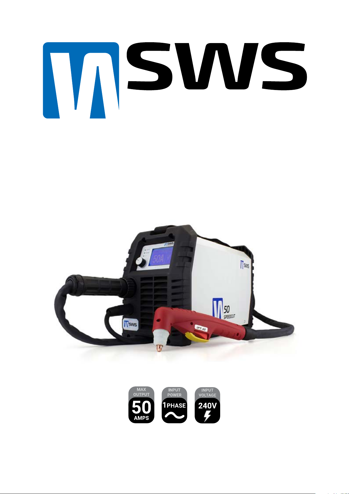
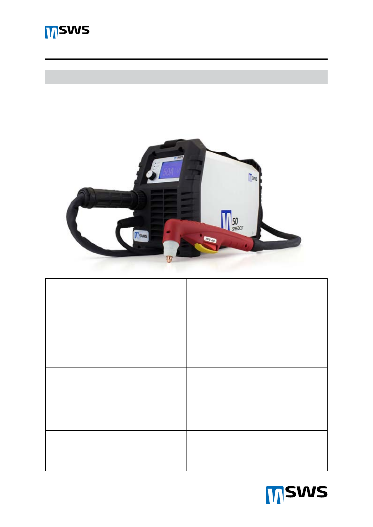
The SWS SPEEDCUT™ 50 is one of the highest quality and most aordable plasma systems on the Australian
market for cutting and gouging of all conductive metals. Featuring pilot arc with auto ignition and automatic
air regulation for optimum performance, you can now depend on a machine that cuts all day at its rated
cutting capacity and to pack more punch when you need it most.
Latest Inverter Technology
Embedded microprocessor with Infineon
components delivers ultimate durability and perfect
cutting characteristics.
Revolutionary Digital Display
Large high visibility durable display allows easy
viewing from a distance and continually provides
you with necessary feedback for optimum cuts.
Smart Programming
The system programming tells you when it’s time
to change consumables, let it cool if the duty cycle
is reached and gives constant feedback with real
time cutting amps displayed maintaining optimal
performance and cut quality.
Pilot Arc
With pilot arc, you benefit from being able to
cut rusty and painted metals while significantly
increasing consumable life.
Automatic Pilot Arc Restart
This feature gives you the ultimate in eiciency by
automatically controlling the pilot arc when cutting
expanded metal or multiple cuts. The pilot arc will
switch on and o when cutting expanded metal
and provides maximum performance when cutting
thicker metal. You benefit from this with less hand
fatigue and the best cutting performance.
Thermal Overload Protection
You can depend on your SWS machine to withstand
harsh working conditions. Thermal overload
protection will kick in once the 50% duty cycle
limit is reached (40° C). Duty cycle will increase as
environmental temperature decreases.
Highly Portable
Dependable IGBT inverter technology ensures a
highly portable and lightweight unit weighing only
11kg.
Meets the Highest Standards
Meets and exceeds the latest Australian, NZ and
International electrical and electromagnetic
compatibility standards. AS60974.1:2006,
IEC60974.10, CE

SPEEDCUT 50
SPEEDCUT 50
SPEEDCUT 50 OPERATING MANUAL 2
INTRODUCTION
1.2 Specications
Cuttable Metals Aluminium, Mild Steel, Stainless Steel, Specialty Metals
Industries General Aluminium Fabrication, Steel and Stainless Steel Fabrication, Stainless
Steel Tank and Pipe Fabrication, Boat Building / Shipyards, Motorcycle custom
shops, Automotive customs shops, Automotive Components and Repairs,
Motorcycle Components and Repairs, Technical Schools, Aerospace, Agriculture,
Farming, Building and Construction, Home Repair Workshops.
Mild Steel Cutting
Capacity 20mm (⅝ in) @ 320 Millimetres/minute (25mm severance)
Stainless Steel Cutting
Capacity
12mm (½ in) @ 380 Millimetres/minute
Aluminium Cutting
Capacity
10mm (⅜ in) @ 380 Millimeters/minute
Input Voltage 1 Phase 230V +/‑ 15% (15 Amp Plug)
Input Hz 50/60 Hz
Minimum Air
Compressor
Requirements
100 L/m ‑ 60 psi
Minimum Generator
Requirements
6.6kW (8.5kVA at 0.8 PF)
Duty Cycle 40° AMB 50% @ 45A100% @ 26A
Duty Cycle 25° AMB 60% @ 50A 100% @ 40A
Cutting Current Range 20A ‑ 50A
Dimensions L 410mm H 180mm W 250mm
Weight 11Kg
Manufactured to
Standards
AS60974.1:2006, IEC60974.10, CE

SPEEDCUT 50
SPEEDCUT 50
SPEEDCUT 50 OPERATING MANUAL 3
WARNING!
ELECTRIC SHOCK - Can kill
‑ Connect and earth (ground) the welding or plasma cutting unit adhering to applicable standards.
‑ Do not touch live electrical parts or electrodes with bare skin, wet gloves or wet clothing.
‑ Insulate yourself from the natural ground and the workpiece.
‑ CNC Port torch arc volatge is 1:1 and can kill ensure only qualified persons connect it.
FUMES AND GASES ‑ Can be dangerous to health.
‑ Keep your head out of the fumes.
‑ Use ventilation, extraction at the welding or cutting arc, or both, to take fumes and gases away
from your breathing zone and the surrounding area.
ARC RAYS ‑ Can injure eyes and burn skin.
‑ Protect your eyes and body. Use an approved welding/plasma cutting helmet and filter lens and
wear protective clothing.
‑ Protect bystanders with suitable screens or curtains.
FIRE HAZARD
‑ Sparks (spatter) can cause fires. Make sure therefore that there are no flammable materials
nearby.
NOISE ‑ Excessive noise can damage hearing.
‑ Protect your ears. Use ear mus or other suitable hearing protection.
‑ Warn all bystanders of the risk.
MALFUNCTION - Call an for expert assistance in the event of a malfunction.
CAUTION
This product is only intended for metal removal and cutting. Any other use may
result in personal injury and equipment damage.
CAUTION
Read and understand the instruction manual before installing or operating.
SAFETY
2.0 Hazards
Arc welding and plasma cutting can be dangerous to yourself and others. Take
special care when welding and cutting. Note your employer’s safety practices
which should be based on manufacturers’ hazard data documents.

SPEEDCUT 50
SPEEDCUT 50
SPEEDCUT 50 OPERATING MANUAL 4
SAFETY
2.1 Precautions
Users of SWS welding and plasma cutting products have the primary responsibility for ensuring that anyone
who works on or near this equipment adheres to all the relevant safety precautions. The following listed
recommendations must be observed along with the standard regulations that apply to the workplace.
All use must be carried out by trained personnel well versed with the safe operation of the equipment.
Incorrect operation of plasma cutting or welding equipment may lead to hazardous events which can result
in serious injury to the user and damage to the equipment. Safety precautions must meet the requirements
that apply to this type of welding or plasma cutting equipment.
1. Persons who use welding or plasma cutting equipment must be familiar with the following:
‑ Welding and plasma cutting machine operation
‑ Location of emergency stops
‑ The machines purpose
‑ Relevant safety precautions
‑ Arc welding and / or hand held plasma cutting
2. The user must make sure that:
‑ No unauthorized person in the vicinity of the working area of the equipment when it is used.
‑ No person is unprotected when the arc is started.
3. The workplace must:
‑ Be suitable for the purpose
‑ Be free from weather
4. Personal safety equipment:
‑ Always wear approved personal safety equipment, such as welding helmets, safety glasses, flame proof
clothing and safety gloves.
‑ Never wear loose fitting items, such as hooded jumpers, bracelets, rings, etc., which can become trapped
or cause serious injury burns.
5. General safety precautions:
‑ Ensure the return cable is connected securely.
‑ Work on high voltage equipment must only be carried out by a qualified electrician or electrical
technician.
‑ Approved fire extinguishing equipment must be clearly marked and in the vicinity.
‑ Lubrication and maintenance must not be carried out on the equipment during operation.
READ AND UNDERSTAND THE OPERATING MANUAL BEFORE
INSTALLING OR USING THIS EQUIPMENT - ALWAYS PROTECT
YOURSELF AND OTHERS!

SPEEDCUT 50
SPEEDCUT 50
SPEEDCUT 50 OPERATING MANUAL 7
INSTALLATION
5.0 Working Environment
• The workspace in which this equipment is installed must be free of excessive grinding dust,
natural dust, flammable and corrosive chemicals, flammable gas or materials, etc. And at no
more than a maximum of 80% humidity.
• When using the equipment outdoors protect the machine from precipitation and direct sun
light. The working temperature environment should be kept within –15°C to +40°C.
• Keep this machine as least 250mm away from walls.
• Ensure the working environment is well ventilated with fan extraction when necessary.
5.1 Preliminary Checks
• Always turn the machine on and let it perform boot cycle before connecting
pressurised air line.
• Ensure compressor/gas regulator pressure is set between 75 ‑ 100 PSI.
5.2 Machine Installation

SPEEDCUT 50
SPEEDCUT 50
SPEEDCUT 50 OPERATING MANUAL 8
Worn Nozzle Worn Electrode
PLASMA TORCH
6.0 Plasma Torch Parts
1‑Stand O Guide
2‑Outside Nozzle/Outside Nozzle 6 Holes (Longer life)
3‑Short Tip
4‑Short Tip 2
5‑Medium Tip
6‑Flat Tip
7‑Extended Tip
8‑Extended Flat Tip
9‑Diuser
10‑Short Electrode
12‑Long Electrode
13‑Plasma Torch Head
14‑Plasma Torch Handle
15‑Trigger Safety
16‑Trigger
17‑ Joint
18‑ Cable Assembly
19‑ Electrode Spanner
20‑ 6 Pin Central Adapter
6.1 Consumables Wear
Worn torch consumables will cause poor cutting performance and will cause the ERROR! Missing electrode
or Nozzle code to display once exhausted. The diagram below illustrates an excessively worn nozzle and
electrode.
Consumables that are made for the torch model are to be used only. IPT40, IPT60
or SC50 models must use the correct genuine consumables.
Not using the correct consumables may result in damaging the plasma torch head
and machine.

SPEEDCUT 50
SPEEDCUT 50
SPEEDCUT 50 OPERATING MANUAL 9
MACHINE OPERATION
7.0 Trigger
The pilot arc can cause serious burns - Never engage trigger
switch when torch is directed towards the eyes, face and body
of yourself and others.
Protect your eyes and body. Use an approved welding/plasma cutting
helmet at and filter lens shade #5 and wear protective clothing.
7.1 Operation
Pull trigger system will adjust air
pressure
then start pilot arc aer
2 seconds.
Release trigger to stop arc and
start the cooling cycle
(15 seconds).
Pull then release trigger to stop
cooling cycle prematurely. (Will
cause premature tip wear if large
amounts of cutting have been
performed).
Push safety switch away with
finger.
Place stando guide, drag tip, or position
torch tip 3‑9mm o the metal at 90 degrees
and pull the trigger. Once the cutting starts
begin to slowly move across the workpiece.
Adjust your speed so that sparks are coming
from the backside of the metal. If sparks are
not visible at the bottom of the metal, you are
not penetrating the metal. This can be caused
by moving too fast, insuicient amperage or
too thick of material for the rated capacity. At
the end of the cut angle, your torch past 90
degrees to completely sever the metal.
When cutting thinner materials typically
under 3mm, you can safely drag the
tip. Materials over this thickness may
prematurely wear the torch consumables.
To make a pierce cut sit the edge of
the nozzle on the metal and direct the
torch angle away from your body.
Once the material starts being
removed slightly li and slowly
rotate the torch towards 90
degrees until you see sparks
coming from th underside of the
metal.
Once you have pierced a
hole through the material,
begin to make the cut at
90 degrees.
NOTE: Cut quality is highly dependent on setup and the cutting parameters such as alignment with
the workpiece, torch stando, cutting speed, gas pressures, and operator ability.
i

SPEEDCUT 50
SPEEDCUT 50
SPEEDCUT 50 OPERATING MANUAL 10
SERVICE
8.0 General Maintenance
Each Use
Weekly
3 Months
6 Months
Visual Check of torch tip
and electrode.
Visually inspect the torch body
tip, electrode, start cartridge and
shield cup and torch lead.
Clean exterior of power source
with a dry brush.
Unplug the power source remove cover and visually
check and carefully clean the interior without
touching any internal electrical components wires
or boards.
Inspect the internal filter regulator/filter for contamination
remove and clean if needed.
NOTE: Never use any alcohol based cleaners to clean
filter or assembly use warm mildly soapy water to clean
catchment and rinse throughly. Replace filter if necessary.
Warning!
There is extremely dangerous voltage, and power levels present inside this
product. Do not attempt to open or repair unless you are a qualified electrical
tradespersons and you are qualified in training in power measurements and
troubleshooting techniques. If major complex sub-assemblies are faulty, then the
Cutting Power Source must be returned to an accredited service provider.

SPEEDCUT 50
SPEEDCUT 50
SPEEDCUT 50 OPERATING MANUAL 11
TROUBLESHOOTING
9.0 Machine Codes
ERROR! Under Pressure Adjust air pressure to 75 PSI
ERROR! Missing Shield Cup Turn machine o and check shield cup is firm.
ERROR! Missing Electrode or Nozzle Turn Machine o and check electrode is secure
replace worn electrode & nozzle replace.
ERROR! Over Temperature Let machine finish cooling cycle until error message
has gone.
ERROR! Electrode Short Circuit Turn Machine o and check electrode is secure and
correct type replace worn electrode & nozzle.
Machine over heats easily Check that there is no obstruction to the fan or
cooling vents.
Insuicient Penetration 1.Cutting too fast.
2.Torch angle wrong.
3.Metal over maximum cutting thickness.
4.Worn torch consumables.
5.Cutting Amperage to low.
6. Mains power supply not suicient
Arc Extinguishes 1.Cutting speed to slow.
2.Torch stando too far from workpiece.
3.Cutting current to high for workpiece.
4.Ground working lead not connected.
5.Worn torch consumables.
6. Mains power supply not suicient
Excessive Slag 1.Cutting Speed to slow.
2.Torch stando too far.
3.Worn torch consumables.
4.Improper cutting Amperage.
Machine won’t switch on 1.Check power supply and breakers.
2.Check Power cable for damage.
2.Air pressure connected before turning unit on.
3. Air pressure set past 100 PSI limit.
3.If there is power supply and no cable damage your
machine may need to be repaired contact us for
further information.
Pilot Arc Wont Start 1.Switch machine o wait until display goes blank
wait 10 seconds then switch on again.
2.Check consumables for wear and replace.
3.Check for loose consumables.
4.Press control dial for air test then retry.
5.Check that torch connector is tightened.
9.1 Other Troubleshooting

SPEEDCUT 50
SPEEDCUT 50
SPEEDCUT 50 OPERATING MANUAL 12
This page is intentionally blank

™
SWS WELDING & CUTTING
WEBSITE: WWW.SWSWELDING.COM.AU
EMAIL: SUPPORT@SWSWELDING.COM.AU
TELEPHONE: (03) 5766 2331
FOR MORE PROFESSIONAL PRODUCTS DELIVERED FAST CHECK OUT...
WWW.SWSWELDING.COM.AU
Other manuals for SPEEDCUT 50
1
Table of contents
Other SWS Welding System manuals
Popular Welding System manuals by other brands

Kemppi
Kemppi master 5001 Operation instructions

Paton
Paton VDI-160E Operation manual

Weldmax
Weldmax Pulse Technik Series instruction manual

Nippon Gases
Nippon Gases MICROTIG DC 162 PULSE Operating and safety instructions

EINHELL
EINHELL 15.749.90 operating instructions

LOKERMANN
LOKERMANN GRAND TIG 200 DC user manual

Adler
Adler MMA-200 instruction manual

Thermal Dynamics
Thermal Dynamics Pak Master 25 operating manual

Lincoln Electric
Lincoln Electric power wave ac/dc 1000 sd Operator's manual

Solaris
Solaris MMA-207 user manual

Miller Electric
Miller Electric XMT 456 CC owner's manual

EWM
EWM alpha Q 351 Progress puls MM FDW operating instructions