Toshiba Carrier RBM-A0601UPVA-UL User manual
Other Toshiba Control Unit manuals

Toshiba
Toshiba IK-HD1E User manual
Toshiba
Toshiba LONWORKS LIU007Z User manual
Toshiba
Toshiba IK-TF5U User manual
Toshiba
Toshiba nv Series User manual
Toshiba
Toshiba IK-CU43A User manual
Toshiba
Toshiba G3 Plus Pack User manual
Toshiba
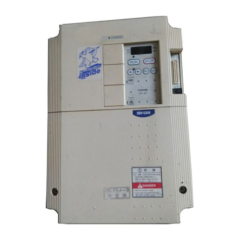
Toshiba TOSVERT VF-A7 User manual
Toshiba
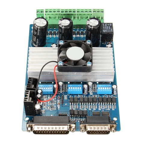
Toshiba 3 axis TB6560 User manual
Toshiba
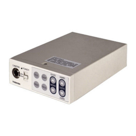
Toshiba IK-CT2D User manual
Toshiba
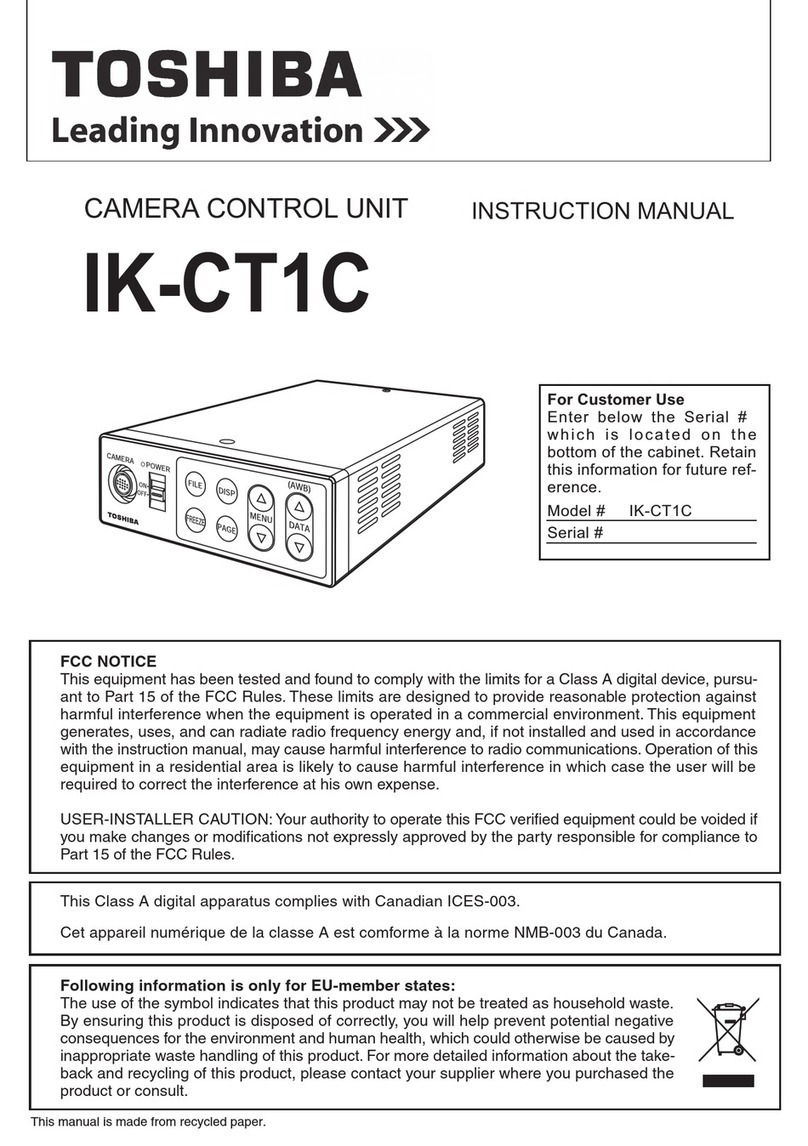
Toshiba IK-CT1C User manual

Toshiba
Toshiba GN-4030-A3 User manual

Toshiba
Toshiba B-8204-QM-R User manual

Toshiba
Toshiba IK-TF7U User manual
Toshiba
Toshiba RBM-SV1121HUPE User manual
Toshiba
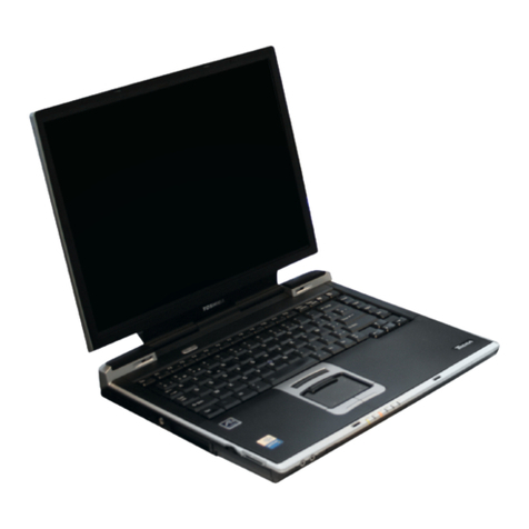
Toshiba TECRA S1 Series Parts list manual
Toshiba
Toshiba V Series User manual
Toshiba
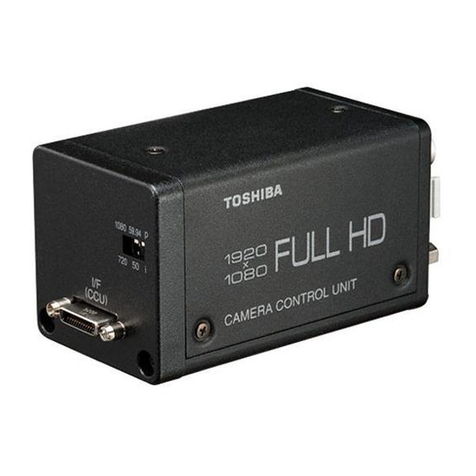
Toshiba IK-HR1CD User manual
Toshiba
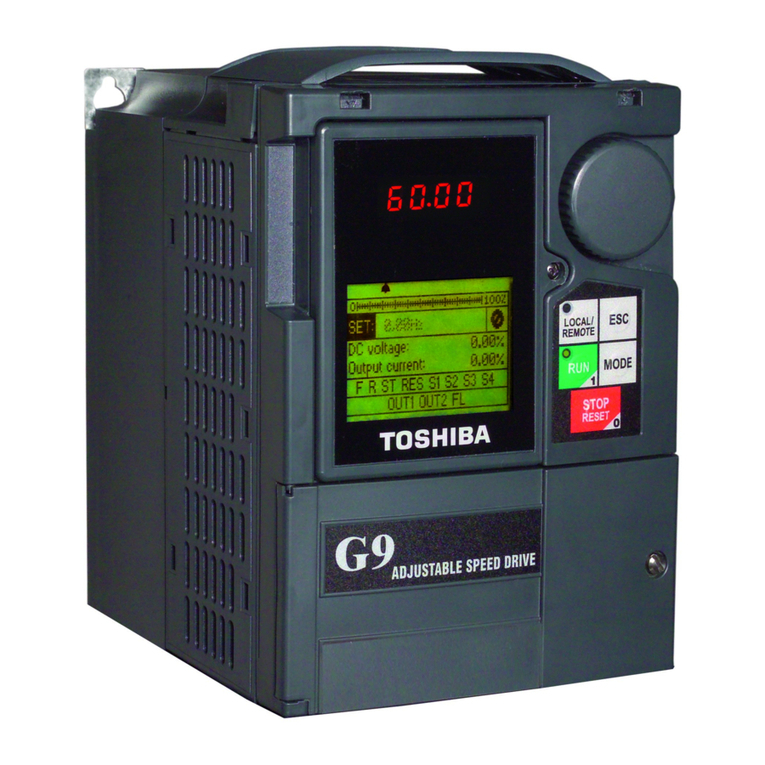
Toshiba ASD 9 Series User manual
Toshiba
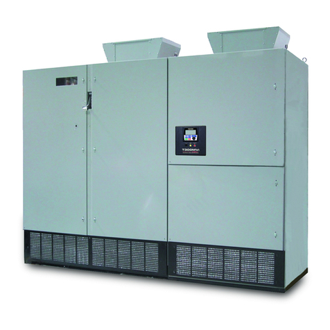
Toshiba T300MVi MEDIUM VOLTAGE User manual
Toshiba
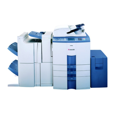
Toshiba e-STUDIO 810 User manual
Popular Control Unit manuals by other brands

Festo
Festo Compact Performance CP-FB6-E Brief description

Elo TouchSystems
Elo TouchSystems DMS-SA19P-EXTME Quick installation guide

JS Automation
JS Automation MPC3034A user manual

JAUDT
JAUDT SW GII 6406 Series Translation of the original operating instructions

Spektrum
Spektrum Air Module System manual

BOC Edwards
BOC Edwards Q Series instruction manual

KHADAS
KHADAS BT Magic quick start

Etherma
Etherma eNEXHO-IL Assembly and operating instructions

PMFoundations
PMFoundations Attenuverter Assembly guide

GEA
GEA VARIVENT Operating instruction

Walther Systemtechnik
Walther Systemtechnik VMS-05 Assembly instructions

Altronix
Altronix LINQ8PD Installation and programming manual
