Sygonix 1888207 User manual

Operating Instructions
Fingerprint code lock
Item No. 1888207

Table of contents
Page
1. Introduction................................................................................................................... 4
2. Explanation of symbols ................................................................................................ 5
3. Intended use................................................................................................................. 5
4. Package contents......................................................................................................... 6
5. Safety instructions........................................................................................................ 7
6. Battery safety information............................................................................................. 9
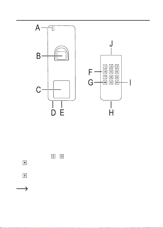
7. Connections and control elements ............................................................................. 10
8. Mounting and connection ........................................................................................... 12
9. Setup.......................................................................................................................... 22
a) IR remote control................................................................................................. 22
b) Code lock ............................................................................................................ 22
10. Programming.............................................................................................................. 23
a) General notes...................................................................................................... 23
b) Activating/exiting programming mode ................................................................. 24
c) Changing the master code .................................................................................. 25
d) Settingtheuserngerprint .................................................................................. 26
e) Tuning-in the user transponder ........................................................................... 30
f) Deleting the user ID............................................................................................. 37
g) Deletingtheuserngerprint ................................................................................ 38
h) Deleting the user transponder............................................................................. 40
i) Deleting all user data........................................................................................... 43
j) Setting the activation duration for output or toggle operation.............................. 44
k) Selecting access mode ....................................................................................... 45
l) Setting the alarm duration ................................................................................... 47
m) Security function for invalid access attempts ...................................................... 48
n) Security function with door sensor ...................................................................... 49
o) Reset................................................................................................................... 50
2

Page
11. Wiegand function........................................................................................................ 52
a) Connection .......................................................................................................... 52
b) Setting Wiegand device ID.................................................................................. 53
c) ConguringtheWiegandoutput.......................................................................... 54
d) UsingngerprintswiththeWiegandcontroller.................................................... 55
12. Interlock function ........................................................................................................ 56
13. Operation.................................................................................................................... 57
a) Enabling the changeover contact........................................................................ 57
b) Enabling the changeover contact via button ....................................................... 57
c) Terminating the alarm sound............................................................................... 57
d) Superuser lock function....................................................................................... 58
14. Sound signals and LED displays................................................................................ 59
15. Troubleshooting.......................................................................................................... 60
16. Care and Cleaning ..................................................................................................... 61
17. Declaration of Conformity (DOC)................................................................................ 61
18. Disposal...................................................................................................................... 62
a) Product................................................................................................................ 62
b) Battery information .............................................................................................. 62
19. Technical Data............................................................................................................ 63
a) Code lock ............................................................................................................ 63
b) IR remote control................................................................................................. 63
3

1. Introduction
Dear customer,
Thank you for purchasing this product.
This product complies with statutory national and European regulations.
To ensure that the product remains in this state and to guarantee safe operation, always
follow the instructions in this manual.
These operating instructions are part of this product. They contain important infor-
mation on setting up and using the product. Do not give this product to a third party
without the operating instructions.
Therefore, retain these operating instructions for reference!
All company and product names are trademarks of their respective owners. All rights re-
served.
If there are any technical questions, please contact: www.conrad.com/contact
4

2. Explanation of symbols
The symbol with the lightning in a triangle indicates that there is a risk to your
health, e.g. due to an electric shock.
The symbol with an exclamation mark in a triangle is used to highlight important
information in these operating instructions. Always read this information carefully.
The arrow symbol indicates special information and tips on how to use the product.
3. Intended use
Thisproductisdesignedtopreventunauthorisedaccesstodoors(e.g.inanofce)andto
activate/disable alarm systems. Control is possible either via suitable transponders or the
integratedngerprintsensor.
Ifyouholdatuned-intransponderinfrontofthecodelockorplaceangerthatisstoredin
thesystemonthengerprintsensor,apotential-freechangeovercontactwillbeactivated
(for contact rating, see chapter “Technical data”). This can be used, for example, to trigger a
door opener or an alarm system.
The product is designed for operation indoors and outdoors (IP66).
For safety purposes, do not convert and/or modify this product. Using the product for pur-
poses other than those described above may damage the product. In addition, improper
usecancausehazardssuchasashortcircuit,reorelectricshock.Readtheinstructions
carefully and store them in a safe place. If you pass the product on to a third party, please
hand over these operating instructions as well.
5

4. Package contents
• Code lock
• IR remote control with CR2025 battery
• 1x transponder card for adding user transponders
• 1x transponder card for deleting user transponders
• Mounting material (2x screws, 2x dowels)
• 1x L-key
• 3x 1N4004 diodes
• Operating instructions
Up-to-Date Operating Instructions
Download the up-to-date operating instructions at www.conrad.com/downloads or scan the
QR code shown. Follow the instructions on the website.
6

5. Safety instructions
Read the operating instructions and safety information carefully. If you do
not follow the safety instructions and information on proper handling in
these operating instructions, we assume no liability for any resulting per-
sonal injury or damage to property. Such cases will invalidate the warranty/
guarantee.
• Theunauthorisedconversionand/ormodicationoftheproductisprohibited
for safety and approval reasons.
• The device is not a toy. Keep out of the reach of children and pets.
• The product is designed for operation indoors and outdoors (IP66). However, it
must never be used in or under water, as this will destroy it.
• Protecttheproductfromextremetemperatures,impacts,ammablegases,
vapours and solvents.
• Never exceed the contact rating for the potential-free changeover contact
speciedinchapter“Technicaldata”.Neverattempttoconnectthecodelock
to a mains voltage, as this may cause a fatal electric shock.
• Please handle the product carefully. Jolts, impacts or a fall even from a low
height may damage the product.
• Do not place the product under any mechanical stress.
• Always observe the safety and operating instructions of any other devices
which are connected to the product (e.g. door openers and alarm systems).
• Always comply with the accident prevention regulations for electrical equip-
ment when using the product in commercial facilities.
• If it is no longer possible to operate the product safely, take it out of opera-
tion and protect it from any accidental use. Safe operation can no longer be
guaranteed if the product:
- is visibly damaged,
- is no longer working properly,
- has been stored for extended periods in poor ambient conditions or
- has been subjected to any serious transport-related stresses.
7

• Do not leave packaging material lying around carelessly. It may become a
dangerous toy for children!
• Maintenance,modicationsandrepairsmustbecarriedoutbyatechnicianor
a specialist repair centre.
• If you are not sure how to operate the product correctly, or if you have any
questions that are not answered in these operating instructions, contact us or
another specialist.
8

6. Battery safety information
Keep batteries out of the reach of children.
Do not leave batteries lying around in the open; there is a risk of them being swallowed by
children or pets. If swallowed, consult a doctor immediately, it could be fatal!
Always ensure that the battery in the IR remote control is inserted with the correct polarity
(observe the plus/+ and minus/- symbols).
Batteriesmust notbe short-circuited,opened, takenapart orthrown intoa re.Thismay
causeareorexplosion!
Never attempt to recharge non-rechargeable batteries, as this may cause an explosion.
Old or depleted batteries may emit chemical liquids that cause damage to the product.
Therefore, if the device is not to be used for a long time (e.g. storage), remove the battery
from the IR remote control.
Leaking or damaged batteries can lead to caustic burning upon skin contact. Therefore, use
suitable protective gloves.
Liquids leaking from batteries are very chemically aggressive. Objects or surfaces coming
into contact with these liquids could be severely damaged. Therefore, store batteries in a
suitable location.
To dispose of batteries in an environmentally friendly manner, see “Disposal” chapter.
9

7. Connections and control elements
A Control LED
B Fingerprint sensor
C Transponder sensor surface
D IR receiver
E Fastening screw
F Keypad for buttons to
G button
H Clip for battery compartment
I button
J IR transmission LED
The wall mounting bracket and the connection cable are located on the back of the
code lock.
10

Connecting cable:
Colour Function
Red 12 V/DC
Black GND
Blue NO contact of the relay
Purple COM contact of the relay
Orange NC contact of the relay
Yellow Input for door opener button (NO contact / normally open contact)
Green Wiegand connection, Data 0, D0
White Wiegand connection, Data 1, D1
Grey Alarm output (minus/-)
Brown Input for door sensor (NC contact / normally closed contact)
Connection for operating voltage (cable: red + black)
The power supply (12 V/DC) must be connected here. Pay attention to the correct polarity.
The code lock requires a current of max. 150 mA. It also requires power for the alarm output
siren (up to 2 A).
Potential-free changeover contact (cable: blue + purple + orange)
The potential-free changeover contact (for contact rating, see “Technical data” chapter) is ac-
tivatedintheeventofasuccessfulaccessattempt(correcttranspondercardorngerprint).
The switching time can be programmed (1 – 99 seconds). Toggle operation is also possible.
Input for separate door opener button (cable: yellow)
By pressing a button (NO contact, normally open contact), the potential-free changeover
contact can be activated. For example, it can be used for manual activation of a door opener.
If you need to connect more than one button, connect them in parallel.
Wiegand data cables (cable: green + white)
You can connect to other devices to the Wiegand interface.
11

Alarm output (cable: grey)
This can be used to control an alarm siren (12 V/DC, max. 2 A).
Input for door sensor (cable: brown)
The code lock uses a door sensor to emit an alarm when the door is opened without a valid
accessattempthavingbeenmadepreviouslyusingatransponderorngerprint.
8. Mounting and connection
Do not mount or connect the product when it is connected to a power supply.
• Unscrew the screw (see chapter 7, item E) on the bottom of the code lock (an L-key for
the special screw is included) and then remove the mounting plate on the back of the
code lock.
• Attach the mounting plate to a wall using suitable screws. Depending on the surface,
dowels may also be required.
If necessary, drill a hole for the connecting cables before attaching the mounting plate.
12

Themountingplatemustbemountedsothatthescrewholeforthexingscrew
points downwards.
Ensure that no cables or wires are damaged when drilling holes or tightening
screws.
• Wire the connection cables according to the following circuit examples. Ensure that there
is suitable insulation (e.g. heat shrink tubing).
• Suitable protective diodes for connecting a door opener are included. They protect the
code lock from damage caused by voltage peaks. Pay attention to the correct polarity,
see following connection examples (the white ring on the protective diode must point in
the direction of the positive terminal/+ when connecting).
Warning!
Never switch the mains voltage via the potential-free changeover contact! There is
a risk of fatal electric shock! Observe the permissible contact rating; see “Technical
data” chapter.
Use suitable cables with different colours. Note the colours and store this informa-
tion together with these instructions.
When connecting the cables, pay attention to the correct polarity (plus/+ and
minus/-).
• Attach the code lock to the mounting plate. Ensure that the cables are not pinched. The
codelockcanbexedtothemountingplateusingthexingscrewonthebottom.Usethe
included L-key that is suitable for the special screw.
13

Connection to conventional voltage/power supply:
If a conventional power supply unit with an output voltage of 12 V/DC will be used to operate
the code lock, please note the following connection diagram:
With “Fail Secure” door opener:
This releases the locking latch only when its operating voltage is applied (common
design for front doors).
Blue
Orange
Purple
Red
Yellow
Brown
Grey
Green
White
Black
A “Fail Secure” door opener
B Power adapter
C Code lock
D Door opener button (NO contact, normally open contact)
E Door sensor (NC contact, normally closed contact)
F Protection diode: The protective diode must be connected near the door opener with the
correct polarity. This protects the code lock from voltage peaks.
G Alarm siren
14

With “Fail Safe” door opener:
The locking latch is only released when the operating voltage is absent (rare type,
used, for example, for escape route doors, as the door can be opened in the event
of a power failure).
Blue
Orange
Purple
Red
Yellow
Brown
Grey
Green
White
Black
A “Fail Safe” door opener
B Power adapter
C Code lock
D Door opener button (NO contact, normally open contact)
E Door sensor (NC contact, normally closed contact)
F Protection diode: The protective diode must be connected near the door opener with the
correct polarity. This protects the code lock from voltage peaks.
G Alarm siren
15

Connection to a special power supply for access control systems:
Suchapowersupplycanbeidentiedbyitsconnectionforthedooropener,amongstother
things.
With “Fail Secure” door opener:
This releases the locking latch only when its operating voltage is applied (common
design for front doors).
Blue
Orange
Purple
Red
Yellow
Brown
Grey
Green
White
Black
A “Fail Secure” door opener
B Special power adapter for access control systems
C Code lock
D Door opener button (NO contact, normally open contact)
E Door sensor (NC contact, normally closed contact)
F Alarm siren
16

With “Fail Safe” door opener:
The locking latch is only released when the operating voltage is absent (rare type,
used, for example, for escape route doors, as the door can be opened in the event
of a power failure).
Blue
Orange
Purple
Red
Yellow
Brown
Grey
Green
White
Black
A “Fail Safe” door opener
B Special power adapter for access control systems
C Code lock
D Door opener button (NO contact, normally open contact)
E Door sensor (NC contact, normally closed contact)
F Alarm siren
17

Circuit diagram with two code locks for double door systems:
For programming, see chapter 12.
The use of two code locks makes it possible, for example, to control special access
systems when accessing a room/area with double doors, of which only one may be
opened.
With “Fail Secure” door opener:
This releases the locking latch only when its operating voltage is applied (common
design for front doors).
A “Fail Secure” door opener
B Power adapter
C Code lock
D Door opener button (NO contact, normally open contact)
E Door sensor (NC contact, normally closed contact)
F Protection diode: The protective diode must be connected near the door opener with the
correct polarity. This protects the code lock from voltage peaks.
18

Blue
Orange
Purple
Red
Yellow
Brown
Grey
Green
White
Black
Blue
Orange
Purple
Red
Yellow
Brown
Grey
Green
White
Black
19

With “Fail Safe” door opener:
The locking latch is only released when the operating voltage is absent (rare type,
used, for example, for escape route doors, as the door can be opened in the event
of a power failure).
A “Fail Safe” door opener
B Power adapter
C Code lock
D Door opener button (NO contact, normally open contact)
E Door sensor (NC contact, normally closed contact)
F Protection diode: The protective diode must be connected near the door opener with the
correct polarity. This protects the code lock from voltage peaks.
G Alarm siren
20
Table of contents
Other Sygonix Door Lock manuals