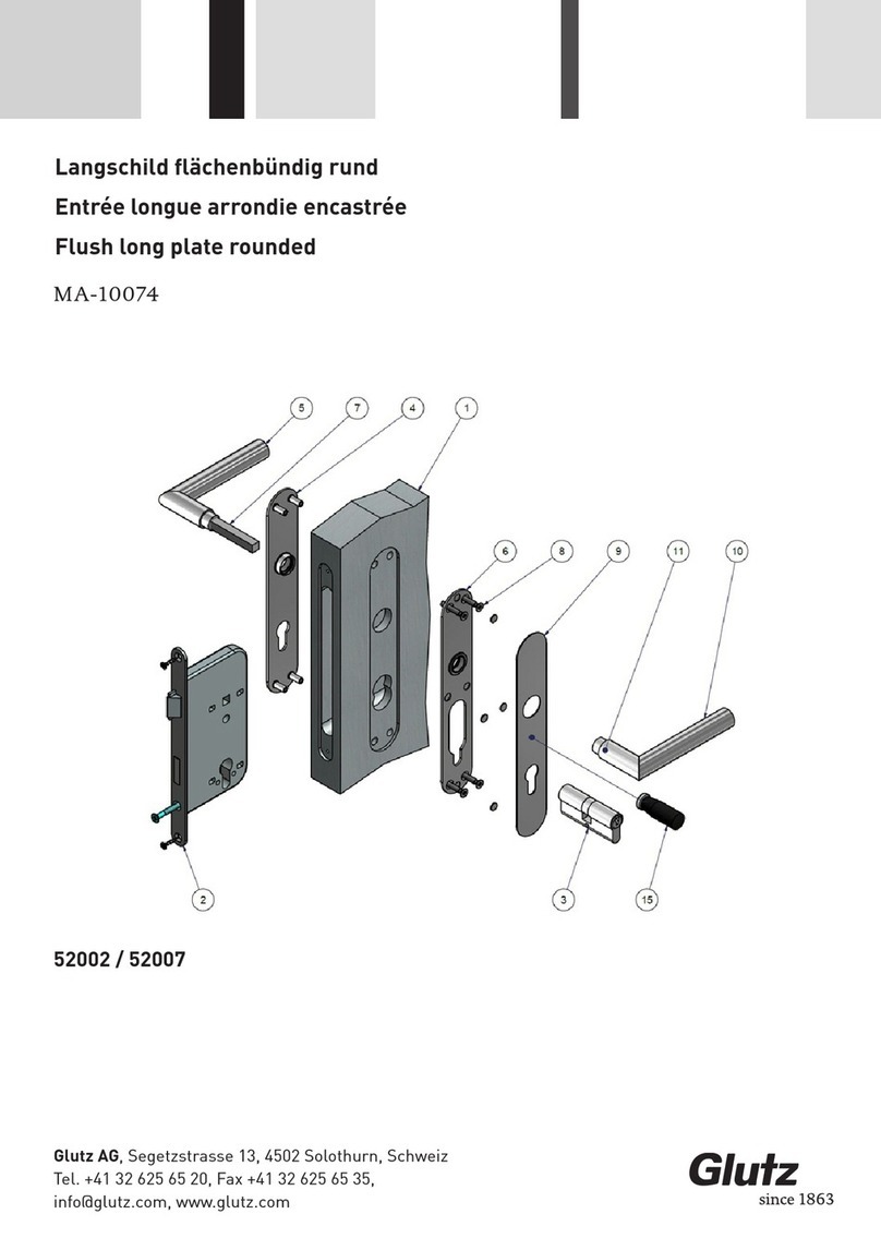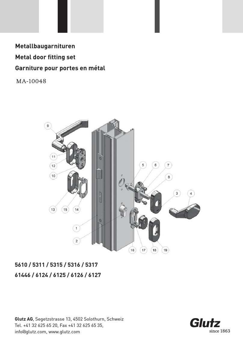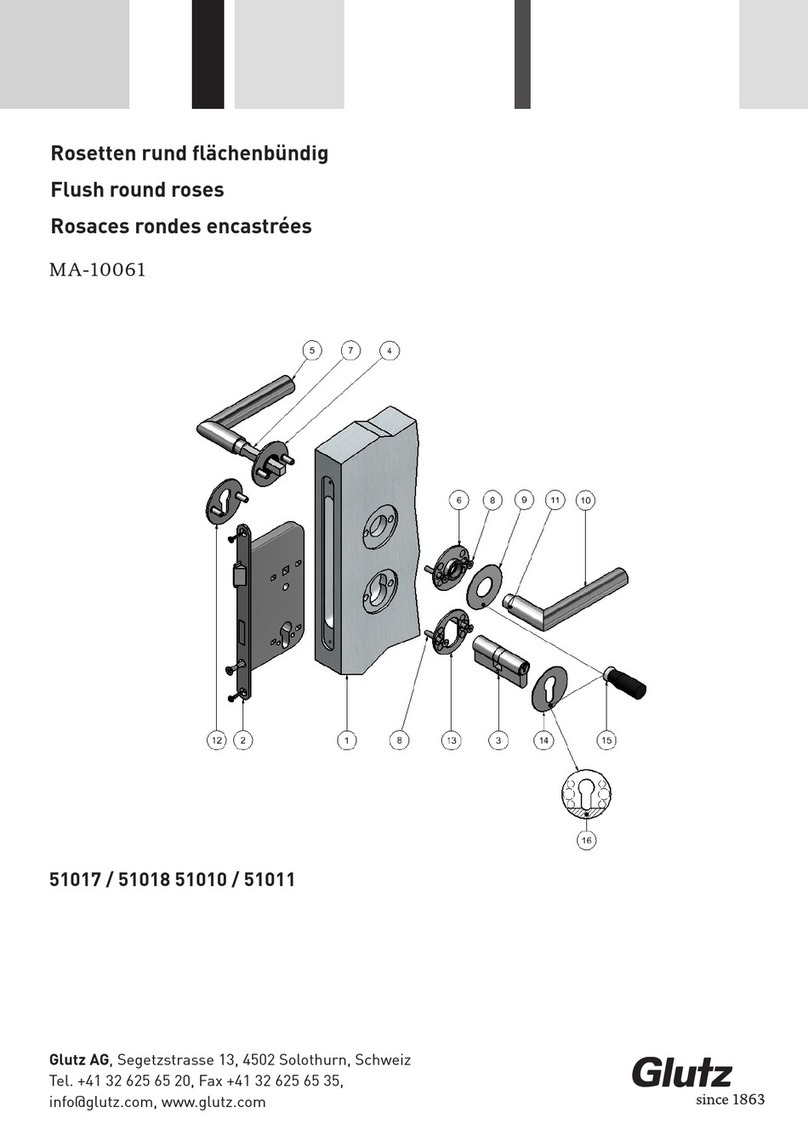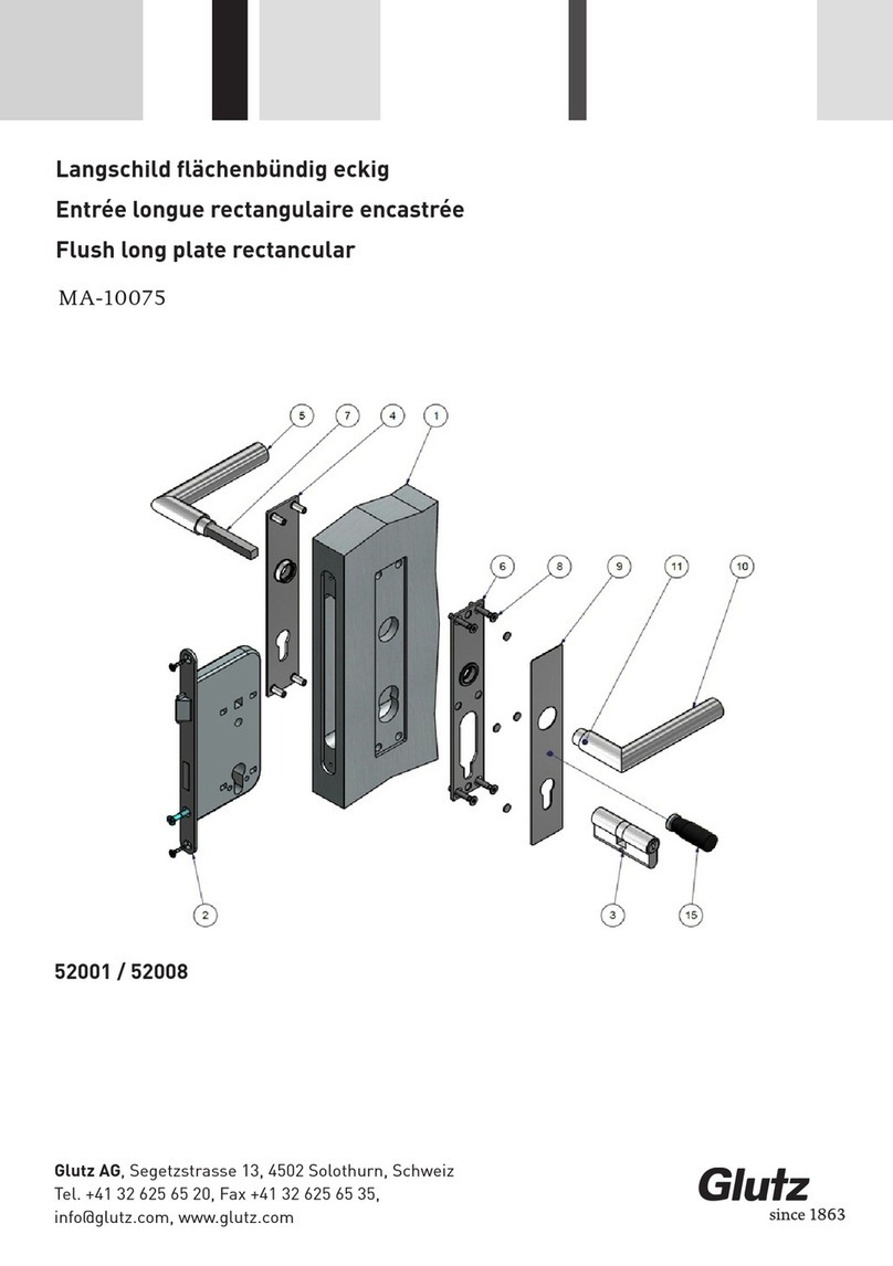
• Mit Glutz Bohrlehre, Türblatt von beiden Seiten anbohren Außenseite: Bei M4 Ø6.5mm, bei M5 Ø
7.5mm) Innenseite: Bei M4 Ø 4.5mm, bei M5 Ø 5.5mm). Schloss entfernen, Bohrungen ganz durch-
bohren bis Schlosskasten (Achtung nicht in Schlosskasten bohren!) Die Bohrungen jeweils ausrei-
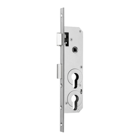
ben (bei Ø 4.5-7.5mm: min. 1.5x45°, max. 2.5x45°).Schloss (14) und Zylinder (15) montieren
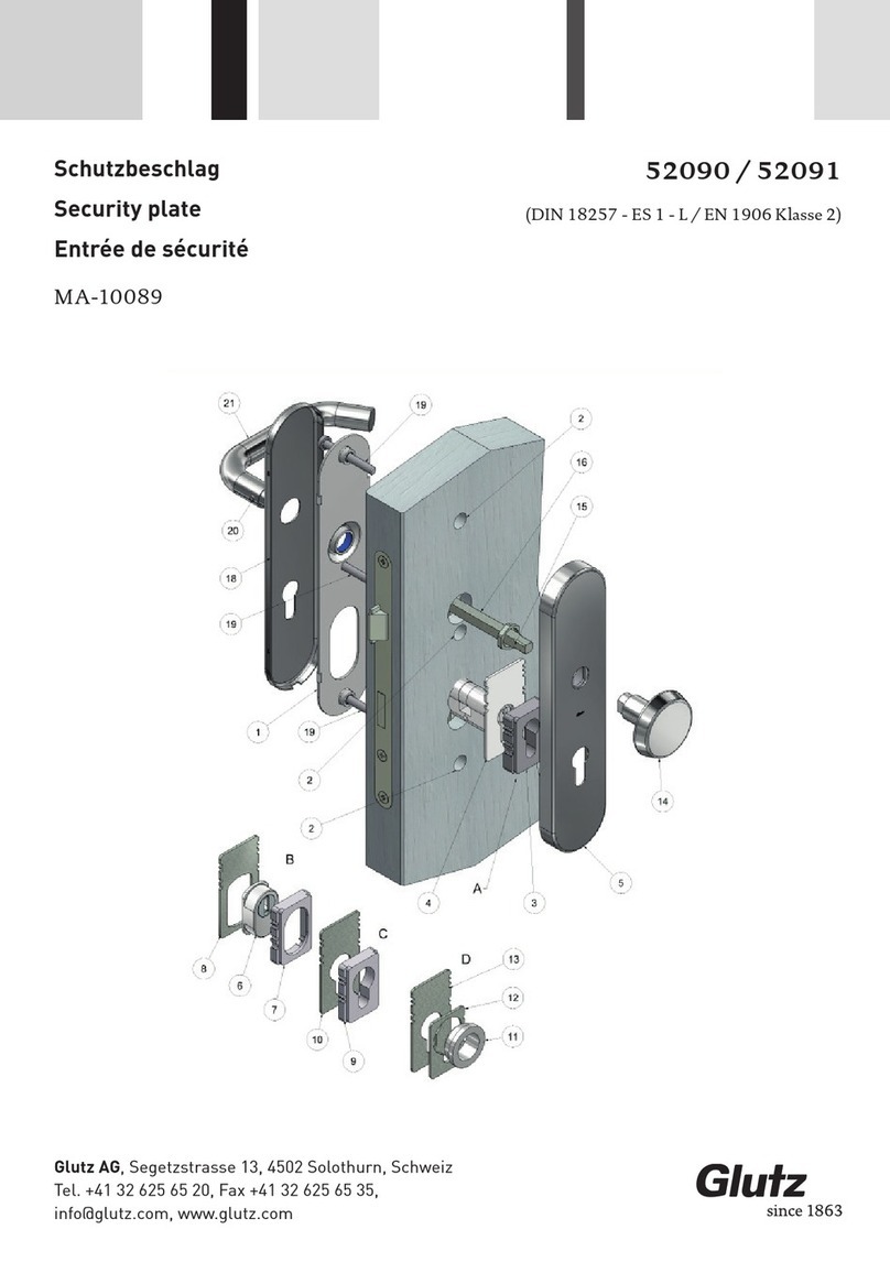
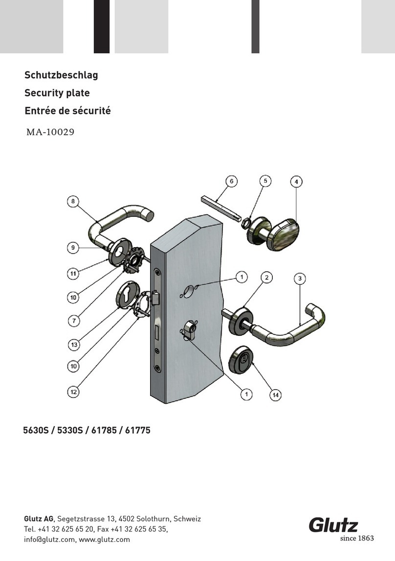
• Rosette (1) auf Aussendrücker (2) (Stiftteil) aufschieben* und durch Schlossnuss stecken, bis Rosette
(1) auf der Türe aufliegt.
• Grundplatte (4) auf Türinnenseite über Vierkantstift stecken. Mit 2 Senkschrauben (5) mit Rosette (1)
leicht verschrauben. Schraubenlänge = Türstärke - 5mm bis -10mm (Es sind Schrauben mit Schrau-
bensicherung zu verwenden).
• Innendrücker (7) zum zentrieren der Grundplatte (4) in Führung stecken (nicht einclipsen!). Senk-
schrauben (5) anziehen (max 1.5 Nm). Lagerung auf Leichtgängigkeit überprüfen, Innendrücker (7)
entfernen
• Rosetten (6) auf Grundplatten (4) aufstecken
• Innendrücker (7) aufschieben* und Heso Schraube einschrauben, bis Durchstanzung am Vierkantstift
erfolgt, anschliessend fest anziehen
• Rosette mit Gewindenocken (8) aussen, mit Grundplatte (9) innen, auf der Tür mit 2 Schrauben (10)
verschrauben (max. 1.5 Nm)
• Abdeckung (11) auf Grundplatte (9) aufstecken.
• Demontage: Abdeckungen (6, 11) mit Demontagemagnet (12) abziehen, Schrauben lösen.
* nur bei easyfix-Montage:Bei der drehbarfesten Lagerung mit easyfix den Drücker mit Druck und
leicht drehen der Bewegung einrasten. Anschliessend durch Zug am Drücker kontrollieren, ob dieser
richtig eingerastet ist.
Montageanleitung
Fixing instructions
• Drill both sides of the door leaf, exterior side: For M4 Ø6.5 mm, for M5 Ø 7.5 mm) Interior side: For M4
Ø 4.5 mm, for M5 Ø 5.5 mm). Remove the lock, drill through to the lock case (Attention: don‘t drill
into the lock case!) Rub out each of the bores (for Ø 4.5-7.5 mm: min. 1.5x45°, max. 2.5x45°).
Fit
lock (14) and cylinder (15).
• Put the rose (1) on the outside lever handle (2) (pin part) and insert it in the lock follower until the rose
(1) rests on the door.
• Put base plate (4) on door inside over square spindle. Screw together the rose (1) with 2 countersunk-
head screws (5) by slightly tightening. Screw length = door thickness - 5 mm to-10 mm (Use screws
with thread lock).
• For centring the base plate (4) insert the inside lever handle (7) in the guide (do not clip!). Tighten the
countersunk-head screws (5) (max 1.5 Nm). Check bearing on free movement, remove inside lever
handle (7)
• Put the rose (6) on the base plate (4)
• Put* inside lever handle (7) and screw the Heso screw until it penetrates the square spindle, subse-
quently screw tight.
• Screw on the door with 2 screws (10) (max. 1.5 Nm) the outside rose with threaded cams (8) with the
inside base plate (9)
• Fit the cover (11) on the base plate (9)
• Dismantling: Remove the covers (6, 11) with the dismantling magnet (12), Loosen the screws
* only with easyfix assembling: In case of fixed mobile bearing with easyfix, click in the lever handle
with pressure and slight rotating movements. Subsequently check by pulling the lever handle, whether
this has clicked in correctly.
Glutz AG, Segetzstrasse 13, 4502 Solothurn, Schweiz
Tel. +41 32 625 65 20, Fax +41 32 625 65 35,


